RU2286255C2 - Device for coextrusion of rubber mixes - Google Patents
Device for coextrusion of rubber mixes Download PDFInfo
- Publication number
- RU2286255C2 RU2286255C2 RU2003105224/12A RU2003105224A RU2286255C2 RU 2286255 C2 RU2286255 C2 RU 2286255C2 RU 2003105224/12 A RU2003105224/12 A RU 2003105224/12A RU 2003105224 A RU2003105224 A RU 2003105224A RU 2286255 C2 RU2286255 C2 RU 2286255C2
- Authority
- RU
- Russia
- Prior art keywords
- rubber
- extrusion
- extruder
- nozzle
- mini
- Prior art date
Links
- 229920001971 elastomer Polymers 0.000 title claims abstract description 58
- 239000005060 rubber Substances 0.000 title claims abstract description 58
- 238000001125 extrusion Methods 0.000 claims abstract description 54
- 238000000034 method Methods 0.000 claims abstract description 14
- 238000004519 manufacturing process Methods 0.000 claims abstract description 12
- 239000000203 mixture Substances 0.000 claims description 49
- 150000001875 compounds Chemical class 0.000 claims description 32
- 230000005611 electricity Effects 0.000 claims description 6
- 230000015572 biosynthetic process Effects 0.000 claims description 3
- 239000004020 conductor Substances 0.000 claims description 2
- 238000005755 formation reaction Methods 0.000 claims 1
- 239000000126 substance Substances 0.000 abstract description 9
- 230000002787 reinforcement Effects 0.000 description 13
- VYPSYNLAJGMNEJ-UHFFFAOYSA-N Silicium dioxide Chemical compound O=[Si]=O VYPSYNLAJGMNEJ-UHFFFAOYSA-N 0.000 description 8
- 239000000945 filler Substances 0.000 description 8
- 239000004071 soot Substances 0.000 description 5
- 239000002184 metal Substances 0.000 description 4
- 238000005096 rolling process Methods 0.000 description 4
- 239000000377 silicon dioxide Substances 0.000 description 4
- 230000003068 static effect Effects 0.000 description 4
- 238000003490 calendering Methods 0.000 description 2
- QFLWZFQWSBQYPS-AWRAUJHKSA-N (3S)-3-[[(2S)-2-[[(2S)-2-[5-[(3aS,6aR)-2-oxo-1,3,3a,4,6,6a-hexahydrothieno[3,4-d]imidazol-4-yl]pentanoylamino]-3-methylbutanoyl]amino]-3-(4-hydroxyphenyl)propanoyl]amino]-4-[1-bis(4-chlorophenoxy)phosphorylbutylamino]-4-oxobutanoic acid Chemical compound CCCC(NC(=O)[C@H](CC(O)=O)NC(=O)[C@H](Cc1ccc(O)cc1)NC(=O)[C@@H](NC(=O)CCCCC1SC[C@@H]2NC(=O)N[C@H]12)C(C)C)P(=O)(Oc1ccc(Cl)cc1)Oc1ccc(Cl)cc1 QFLWZFQWSBQYPS-AWRAUJHKSA-N 0.000 description 1
- 244000043261 Hevea brasiliensis Species 0.000 description 1
- CBENFWSGALASAD-UHFFFAOYSA-N Ozone Chemical compound [O-][O+]=O CBENFWSGALASAD-UHFFFAOYSA-N 0.000 description 1
- 238000009825 accumulation Methods 0.000 description 1
- 230000032683 aging Effects 0.000 description 1
- 239000007767 bonding agent Substances 0.000 description 1
- 239000006229 carbon black Substances 0.000 description 1
- 239000011231 conductive filler Substances 0.000 description 1
- 230000007547 defect Effects 0.000 description 1
- 238000003912 environmental pollution Methods 0.000 description 1
- 239000003292 glue Substances 0.000 description 1
- 238000009434 installation Methods 0.000 description 1
- VNWKTOKETHGBQD-UHFFFAOYSA-N methane Chemical compound C VNWKTOKETHGBQD-UHFFFAOYSA-N 0.000 description 1
- 229920003052 natural elastomer Polymers 0.000 description 1
- 229920001194 natural rubber Polymers 0.000 description 1
- LVTJOONKWUXEFR-FZRMHRINSA-N protoneodioscin Natural products O(C[C@@H](CC[C@]1(O)[C@H](C)[C@@H]2[C@]3(C)[C@H]([C@H]4[C@@H]([C@]5(C)C(=CC4)C[C@@H](O[C@@H]4[C@H](O[C@H]6[C@@H](O)[C@@H](O)[C@@H](O)[C@H](C)O6)[C@@H](O)[C@H](O[C@H]6[C@@H](O)[C@@H](O)[C@@H](O)[C@H](C)O6)[C@H](CO)O4)CC5)CC3)C[C@@H]2O1)C)[C@H]1[C@H](O)[C@H](O)[C@H](O)[C@@H](CO)O1 LVTJOONKWUXEFR-FZRMHRINSA-N 0.000 description 1
- 229920003051 synthetic elastomer Polymers 0.000 description 1
- 239000005061 synthetic rubber Substances 0.000 description 1
Images
Classifications
-
- B—PERFORMING OPERATIONS; TRANSPORTING
- B29—WORKING OF PLASTICS; WORKING OF SUBSTANCES IN A PLASTIC STATE IN GENERAL
- B29C—SHAPING OR JOINING OF PLASTICS; SHAPING OF MATERIAL IN A PLASTIC STATE, NOT OTHERWISE PROVIDED FOR; AFTER-TREATMENT OF THE SHAPED PRODUCTS, e.g. REPAIRING
- B29C48/00—Extrusion moulding, i.e. expressing the moulding material through a die or nozzle which imparts the desired form; Apparatus therefor
- B29C48/16—Articles comprising two or more components, e.g. co-extruded layers
-
- B—PERFORMING OPERATIONS; TRANSPORTING
- B60—VEHICLES IN GENERAL
- B60C—VEHICLE TYRES; TYRE INFLATION; TYRE CHANGING; CONNECTING VALVES TO INFLATABLE ELASTIC BODIES IN GENERAL; DEVICES OR ARRANGEMENTS RELATED TO TYRES
- B60C19/00—Tyre parts or constructions not otherwise provided for
- B60C19/08—Electric-charge-dissipating arrangements
-
- B—PERFORMING OPERATIONS; TRANSPORTING
- B29—WORKING OF PLASTICS; WORKING OF SUBSTANCES IN A PLASTIC STATE IN GENERAL
- B29C—SHAPING OR JOINING OF PLASTICS; SHAPING OF MATERIAL IN A PLASTIC STATE, NOT OTHERWISE PROVIDED FOR; AFTER-TREATMENT OF THE SHAPED PRODUCTS, e.g. REPAIRING
- B29C48/00—Extrusion moulding, i.e. expressing the moulding material through a die or nozzle which imparts the desired form; Apparatus therefor
- B29C48/03—Extrusion moulding, i.e. expressing the moulding material through a die or nozzle which imparts the desired form; Apparatus therefor characterised by the shape of the extruded material at extrusion
- B29C48/07—Flat, e.g. panels
-
- B—PERFORMING OPERATIONS; TRANSPORTING
- B29—WORKING OF PLASTICS; WORKING OF SUBSTANCES IN A PLASTIC STATE IN GENERAL
- B29C—SHAPING OR JOINING OF PLASTICS; SHAPING OF MATERIAL IN A PLASTIC STATE, NOT OTHERWISE PROVIDED FOR; AFTER-TREATMENT OF THE SHAPED PRODUCTS, e.g. REPAIRING
- B29C48/00—Extrusion moulding, i.e. expressing the moulding material through a die or nozzle which imparts the desired form; Apparatus therefor
- B29C48/16—Articles comprising two or more components, e.g. co-extruded layers
- B29C48/18—Articles comprising two or more components, e.g. co-extruded layers the components being layers
- B29C48/19—Articles comprising two or more components, e.g. co-extruded layers the components being layers the layers being joined at their edges
-
- B—PERFORMING OPERATIONS; TRANSPORTING
- B29—WORKING OF PLASTICS; WORKING OF SUBSTANCES IN A PLASTIC STATE IN GENERAL
- B29C—SHAPING OR JOINING OF PLASTICS; SHAPING OF MATERIAL IN A PLASTIC STATE, NOT OTHERWISE PROVIDED FOR; AFTER-TREATMENT OF THE SHAPED PRODUCTS, e.g. REPAIRING
- B29C48/00—Extrusion moulding, i.e. expressing the moulding material through a die or nozzle which imparts the desired form; Apparatus therefor
- B29C48/16—Articles comprising two or more components, e.g. co-extruded layers
- B29C48/18—Articles comprising two or more components, e.g. co-extruded layers the components being layers
- B29C48/21—Articles comprising two or more components, e.g. co-extruded layers the components being layers the layers being joined at their surfaces
-
- B—PERFORMING OPERATIONS; TRANSPORTING
- B29—WORKING OF PLASTICS; WORKING OF SUBSTANCES IN A PLASTIC STATE IN GENERAL
- B29C—SHAPING OR JOINING OF PLASTICS; SHAPING OF MATERIAL IN A PLASTIC STATE, NOT OTHERWISE PROVIDED FOR; AFTER-TREATMENT OF THE SHAPED PRODUCTS, e.g. REPAIRING
- B29C48/00—Extrusion moulding, i.e. expressing the moulding material through a die or nozzle which imparts the desired form; Apparatus therefor
- B29C48/25—Component parts, details or accessories; Auxiliary operations
- B29C48/30—Extrusion nozzles or dies
- B29C48/305—Extrusion nozzles or dies having a wide opening, e.g. for forming sheets
- B29C48/307—Extrusion nozzles or dies having a wide opening, e.g. for forming sheets specially adapted for bringing together components, e.g. melts within the die
-
- B—PERFORMING OPERATIONS; TRANSPORTING
- B29—WORKING OF PLASTICS; WORKING OF SUBSTANCES IN A PLASTIC STATE IN GENERAL
- B29C—SHAPING OR JOINING OF PLASTICS; SHAPING OF MATERIAL IN A PLASTIC STATE, NOT OTHERWISE PROVIDED FOR; AFTER-TREATMENT OF THE SHAPED PRODUCTS, e.g. REPAIRING
- B29C48/00—Extrusion moulding, i.e. expressing the moulding material through a die or nozzle which imparts the desired form; Apparatus therefor
- B29C48/25—Component parts, details or accessories; Auxiliary operations
- B29C48/30—Extrusion nozzles or dies
- B29C48/35—Extrusion nozzles or dies with rollers
-
- B—PERFORMING OPERATIONS; TRANSPORTING
- B29—WORKING OF PLASTICS; WORKING OF SUBSTANCES IN A PLASTIC STATE IN GENERAL
- B29C—SHAPING OR JOINING OF PLASTICS; SHAPING OF MATERIAL IN A PLASTIC STATE, NOT OTHERWISE PROVIDED FOR; AFTER-TREATMENT OF THE SHAPED PRODUCTS, e.g. REPAIRING
- B29C48/00—Extrusion moulding, i.e. expressing the moulding material through a die or nozzle which imparts the desired form; Apparatus therefor
- B29C48/25—Component parts, details or accessories; Auxiliary operations
- B29C48/36—Means for plasticising or homogenising the moulding material or forcing it through the nozzle or die
- B29C48/395—Means for plasticising or homogenising the moulding material or forcing it through the nozzle or die using screws surrounded by a cooperating barrel, e.g. single screw extruders
- B29C48/397—Means for plasticising or homogenising the moulding material or forcing it through the nozzle or die using screws surrounded by a cooperating barrel, e.g. single screw extruders using a single screw
-
- B—PERFORMING OPERATIONS; TRANSPORTING
- B29—WORKING OF PLASTICS; WORKING OF SUBSTANCES IN A PLASTIC STATE IN GENERAL
- B29C—SHAPING OR JOINING OF PLASTICS; SHAPING OF MATERIAL IN A PLASTIC STATE, NOT OTHERWISE PROVIDED FOR; AFTER-TREATMENT OF THE SHAPED PRODUCTS, e.g. REPAIRING
- B29C48/00—Extrusion moulding, i.e. expressing the moulding material through a die or nozzle which imparts the desired form; Apparatus therefor
- B29C48/25—Component parts, details or accessories; Auxiliary operations
- B29C48/36—Means for plasticising or homogenising the moulding material or forcing it through the nozzle or die
- B29C48/49—Means for plasticising or homogenising the moulding material or forcing it through the nozzle or die using two or more extruders to feed one die or nozzle
-
- B—PERFORMING OPERATIONS; TRANSPORTING
- B60—VEHICLES IN GENERAL
- B60C—VEHICLE TYRES; TYRE INFLATION; TYRE CHANGING; CONNECTING VALVES TO INFLATABLE ELASTIC BODIES IN GENERAL; DEVICES OR ARRANGEMENTS RELATED TO TYRES
- B60C11/00—Tyre tread bands; Tread patterns; Anti-skid inserts
-
- B—PERFORMING OPERATIONS; TRANSPORTING
- B29—WORKING OF PLASTICS; WORKING OF SUBSTANCES IN A PLASTIC STATE IN GENERAL
- B29D—PRODUCING PARTICULAR ARTICLES FROM PLASTICS OR FROM SUBSTANCES IN A PLASTIC STATE
- B29D30/00—Producing pneumatic or solid tyres or parts thereof
- B29D30/06—Pneumatic tyres or parts thereof (e.g. produced by casting, moulding, compression moulding, injection moulding, centrifugal casting)
- B29D30/52—Unvulcanised treads, e.g. on used tyres; Retreading
- B29D2030/526—Unvulcanised treads, e.g. on used tyres; Retreading the tread comprising means for discharging the electrostatic charge, e.g. conductive elements or portions having conductivity higher than the tread rubber
-
- Y—GENERAL TAGGING OF NEW TECHNOLOGICAL DEVELOPMENTS; GENERAL TAGGING OF CROSS-SECTIONAL TECHNOLOGIES SPANNING OVER SEVERAL SECTIONS OF THE IPC; TECHNICAL SUBJECTS COVERED BY FORMER USPC CROSS-REFERENCE ART COLLECTIONS [XRACs] AND DIGESTS
- Y10—TECHNICAL SUBJECTS COVERED BY FORMER USPC
- Y10S—TECHNICAL SUBJECTS COVERED BY FORMER USPC CROSS-REFERENCE ART COLLECTIONS [XRACs] AND DIGESTS
- Y10S152/00—Resilient tires and wheels
- Y10S152/02—Static discharge
Abstract
Description
Настоящее изобретение касается способа, предназначенного для изготовления пневматической шины, содержащей несколько смесей, включающих в качестве основного наполнителя непроводящий наполнитель, такой как кремнезем или смеси с низким содержанием сажи, при этом по меньшей мере две из этих смесей входят в состав протектора. Изобретение касается также устройства, предназначенного для осуществления данного способа.The present invention relates to a method for manufacturing a pneumatic tire containing several mixtures comprising a non-conductive filler as the main filler, such as silica or mixtures with a low soot content, with at least two of these mixtures being included in the tread. The invention also relates to a device for implementing this method.
В настоящее время все большее значение приобретают проблемы загрязнения окружающей среды самодвижущимися транспортными средствами, борьба с которым носит приоритетный характер, поэтому производители шин стремятся получить пневматическую шину, характеризующуюся одновременно очень низким сопротивлением качению, максимальным сцеплением с дорожным покрытием, как с сухим, так и влажным, или заснеженным, или обледенелым, высокой износоустойчивостью и, наконец, низким уровнем шума при движении.Nowadays, the problems of environmental pollution by self-propelled vehicles are becoming increasingly important, the fight against which is a priority, therefore, tire manufacturers are striving to get a pneumatic tire, characterized at the same time by very low rolling resistance, maximum adhesion to the road surface, both dry and wet or snowy or icy, high wear resistance and, finally, low noise when driving.
Для решения этой задачи в европейской патентной заявке ЕР А 501227 описана пневматическая шина с протектором, содержащим кремнезем в качестве основного активного наполнителя. Несмотря на то что такое решение является наилучшим компромиссом между вышеперечисленными свойствами, тем не менее, как оказалось, в зависимости от типа транспортных средств пневматические шины с протектором, содержащим кремнезем в качестве основного активного наполнителя, способны в той или иной степени накапливать статическое электричество при трении шины на дороге во время езды, образующееся из-за отсутствия проводящих свойств у кремнезема.To solve this problem, European patent application EP A 501227 describes a pneumatic tire with a tread containing silica as the main active filler. Despite the fact that such a solution is the best compromise between the above properties, nevertheless, as it turned out, depending on the type of vehicles, pneumatic tires with a tread containing silica as the main active filler are capable of accumulating static electricity to a greater or lesser extent. tires on the road while riding, formed due to the lack of conductive properties of silica.
Накапливаемое таким образом в шине статическое электричество при определенных условиях становится причиной неприятного электрического шока для пользователя транспортного средства, когда ему приходится прикасаться к кузову. Кроме того, это статическое электричество ускоряет старение пневматической шины от озона, образующегося при электрическом разряде. Оно может также стать причиной, в зависимости от характера дорожного покрытия и типа транспортного средства, плохой работы радиоприборов, установленных на этом транспортном средстве, из-за создаваемых помех.The static electricity thus accumulated in the tire under certain conditions causes an unpleasant electric shock for the vehicle user when he has to touch the body. In addition, this static electricity accelerates the aging of the pneumatic tire from ozone generated by electrical discharge. It may also cause, depending on the nature of the road surface and the type of vehicle, the poor operation of the radio devices installed on this vehicle due to the interference created.
Эта проблема накопления статического электричества в пневматической шине и большинства вытекающих отсюда недостатков возникла давно, еще когда в качестве основного активного наполнителя применялась сажа.This problem of accumulation of static electricity in the pneumatic tire and most of the shortcomings resulting from this arose long ago, when soot was used as the main active filler.
В заявке ЕР А 0658452 описано использование давно известных принципов к так называемой современной пневматической шине, позволяющее решить основные проблемы, связанные с техническими решениями, предложенными ранее в различных документах, в частности, связанные неоднородностью элементов, входящих в состав структуры пневматической шины. Предложенное решение заключалось во включении полосы или вставки из токопроводящей резиновой смеси, предпочтительно выполненной по всей окружности пневматической шины и соединяющей поверхность протектора либо с одним из вершинных слоев, либо с каркасной арматурой, либо с любой другой частью пневматической шины, в достаточной мере являющейся электрическим проводником, при этом необходимая электропроводимость обеспечивалась за счет присутствия соответствующей сажи.In the application EP A 0658452 describes the use of long-known principles for the so-called modern pneumatic tire, which allows to solve the main problems associated with technical solutions proposed earlier in various documents, in particular, related to the heterogeneity of the elements that make up the structure of the pneumatic tire. The proposed solution was to include a strip or insert of conductive rubber compound, preferably made around the entire circumference of the pneumatic tire and connecting the tread surface with either one of the top layers, or with frame reinforcement, or with any other part of the pneumatic tire that is sufficiently an electrical conductor , while the necessary electrical conductivity was provided due to the presence of the corresponding soot.
Если такое решение вполне подходит для пневматической шины с протектором, содержащим только одну непроводящую смесь, например, протектором шины легкового автомобиля, то иначе обстоит дело с пневматической шиной, содержащей несколько пластов резиновых смесей над каркасной арматурой и пласты резиновых смесей между арматурой вершины и каркасной арматурой, как в любой пневматической шине, эксплуатируемой при повышенной стабилизированной температуре качения, как в случае большегрузных транспортных средств или скоростных автомобилей.If such a solution is quite suitable for a pneumatic tire with a tread containing only one non-conductive mixture, for example, a tread of a passenger car tire, then the situation is different with a pneumatic tire containing several layers of rubber compounds above the frame reinforcement and layers of rubber compounds between the top and frame reinforcement as in any pneumatic tire operated at a high stabilized rolling temperature, as in the case of heavy vehicles or high-speed cars.
Действительно, если по той или иной причине возникает необходимость оснастить пневматическую шину или внутреннюю часть протектора (часть, не входящую в контакт с дорожным покрытием) непроводящим пластом между арматурой вершины и внешней частью (входящей в контакт с дорожным покрытием) протектора, ставшей проводящей благодаря присутствию окружной вставки или полосы, то эту внутреннюю часть необходимо выполнить проводящей. Точно так же, пласт между каркасной арматурой и арматурой вершины, характеризующийся значительной толщиной в зоне краев слоев вершины, тоже необходимо выполнить проводящим, если он таковым не является изначально.Indeed, if for one reason or another it becomes necessary to equip the pneumatic tire or the inner part of the tread (the part not coming in contact with the road surface) with a non-conductive layer between the top reinforcement and the outer part (coming in contact with the road surface) of the tread, which has become conductive due to the presence of circumferential insert or strip, then this inner part must be made conductive. Similarly, the formation between the wireframe reinforcement and the vertex reinforcement, characterized by a significant thickness in the region of the edges of the vertex layers, must also be made conductive, if it is not initially.
Как описано во французской заявке FR 97/02276, поданной на имя заявителя, первое решение состоит в обеспечении электрической связи между двумя первыми проводящими или выполненными проводящими пластами, разделенными третьим непроводящим пластом, при помощи по меньшей мере одной полосы из резиновой смеси, имеющей небольшую толщину, длину и ширину, установленной между двумя сторонами сшивания третьего непроводящего пласта и соприкасающейся со средствами, обеспечивающими проводимость двух первых пластов, соединенных электрически. Хотя, с точки зрения промышленной применимости, это решение является приемлемым, такой способ требует дополнительной операции по установке полосы и приводит к удорожанию производства.As described in French application FR 97/02276, filed in the name of the applicant, the first solution is to provide electrical communication between the two first conductive or made conductive layers separated by a third non-conductive layer using at least one strip of rubber compound having a small thickness , the length and width established between the two sides of the stitching of the third non-conductive layer and in contact with means providing conductivity of the first two layers, connected electrically. Although, from the point of view of industrial applicability, this solution is acceptable, such a method requires additional operation to install the strip and leads to higher cost of production.
Второе решение, описанное в международной заявке WO 99/43506, поданной на имя заявителя, состоит в оснащении каждого непроводящего пласта окружной вставкой из проводящей смеси и, после экструзии этого пласта при помощи обычных средств экструзии, в последующем соединении между собой двух элементов перед их установкой на вершину, при этом пласты содержат общую контактную стенку, а ширина вставки одного из пластов на уровне контактной стенки по меньшей мере равна 10-кратной ширине вставки другого пласта на этом же уровне. Такой способ позволяет выполнить проводимым каждый пласт и обеспечивает электрическое соединение между ними и каркасной арматурой. Однако этот способ становится слишком сложным, если речь идет не просто о двух пластах, содержащих две различные резиновые смеси, а о выполнении трех, четырех и более пластов с различными резиновыми смесями.The second solution, described in international application WO 99/43506, filed in the name of the applicant, consists in equipping each non-conductive layer with a circular insert of a conductive mixture and, after extrusion of this layer using conventional extrusion means, in the subsequent connection of the two elements together before installation to the top, while the layers contain a common contact wall, and the width of the insert of one of the layers at the level of the contact wall is at least equal to 10 times the width of the insert of the other layer at the same level. This method allows each layer to be carried out and provides an electrical connection between them and the frame reinforcement. However, this method becomes too complicated if it is not just about two layers containing two different rubber compounds, but about the implementation of three, four or more layers with different rubber compounds.
Кроме того, некоторые резиновые смеси обладают настолько разными реологическими свойствами, что их склеивание вызывает большие проблемы. В частности, это происходит, когда одна смесь является более подверженной к отслаиванию, чем другая. Если, например, требуется соединить между собой такие смеси внутри протектора и избежать при этом использования связующего агента, такого как специальный клей или специальный каучук, прибегают к соэкструзии, которая, кроме всего прочего, представляет интерес с точки зрения снижения производственных затрат. Действительно, при такой соэкструзии различные вещества, находящиеся под действием раздельных экструзионных шнеков, нагнетаются к общему экструзионному отверстию, позволяющему соединить эти вещества в горячем состоянии и под давлением.In addition, some rubber compounds have such different rheological properties that their bonding causes great problems. In particular, this occurs when one mixture is more prone to peeling than the other. If, for example, it is required to interconnect such mixtures inside the tread and to avoid using a bonding agent such as special glue or special rubber, resort to coextrusion, which, among other things, is of interest from the point of view of reducing production costs. Indeed, with such coextrusion, various substances under the action of separate extrusion screws are pumped to a common extrusion hole, which allows these substances to be connected in a hot state and under pressure.
В данной конфигурации можно транспонировать одновременную экструзию на второе техническое решение. Так, в каждом веществе можно выполнять вставку на входе экструзионного отверстия при помощи двух мини-экструдеров, при этом сопло каждого мини-экструдера проходит через каждое вещество таким образом, что в соответствии со вторым решением одна из вставок содержит основание шириной, по меньшей мере в десять раз превышающей ширину основания находящейся напротив вставки из второго вещества. Однако такое решение приводит, с одной стороны, к увеличению габаритов экструдера и, с другой стороны, требует очень сложных операций по замене экструдируемого вещества и по очистке экструдеров.In this configuration, simultaneous extrusion can be transposed into a second technical solution. So, in each substance, it is possible to insert at the inlet of the extrusion hole using two mini-extruders, while the nozzle of each mini-extruder passes through each substance in such a way that, in accordance with the second solution, one of the inserts contains a base with a width of at least ten times the width of the base opposite the insert of the second substance. However, such a solution leads, on the one hand, to an increase in the dimensions of the extruder and, on the other hand, requires very complex operations to replace the extrudable substance and to clean the extruders.
Объектом настоящего изобретения является устройство для соэкструзии и способ получения устройства, в частности, предназначенные для изготовления пневматической шины, содержащей по меньшей мере два пласта из резиновых смесей, не проводящих электричество, и кольцевую вставку из проводящей смеси, обеспечивающую диссипацию электрических зарядов, индуцированных при качении шины, при этом устройство и способ являются максимально простыми и использующими вещество для выполнения вставки только в необходимом для этого количестве.The object of the present invention is a device for coextrusion and a method for producing a device, in particular, intended for the manufacture of a pneumatic tire containing at least two layers of rubber compounds that do not conduct electricity, and an annular insert of a conductive mixture that dissipates the electric charges induced by rolling tires, while the device and method are as simple as possible and use the substance to perform the insert only in the quantity necessary for this.
В соответствии с настоящим изобретением способ получения элемента на основе резиновых смесей, применяемый для изготовления пневматических шин, отличается тем, что включает в себя следующие этапы:In accordance with the present invention, a method for producing an element based on rubber compounds used for the manufacture of pneumatic tires is characterized in that it includes the following steps:
- путем соэкструзии шприцуют по меньшей мере два пласта резиновой смеси при помощи основного экструдера, содержащего по меньшей мере два экструзионных шнека, каждый из которых взаимодействует соответственно с выпускным каналом, соединенным с одним и тем же экструзионным отверстием, ограниченным первой и второй стенками;- by coextrusion, at least two layers of the rubber mixture are squeezed using a main extruder containing at least two extrusion screws, each of which interacts respectively with an outlet channel connected to the same extrusion hole bounded by the first and second walls;
- через два пласта на входе экструзионного отверстия путем соэкструзии вводят по меньшей мере одну вставку из резиновой смеси при помощи сопла мини-экструдера, при этом сопло проходит через два выпускных канала.- through two layers at the inlet of the extrusion hole by coextrusion, at least one insert from the rubber mixture is introduced using the nozzle of a mini-extruder, while the nozzle passes through two outlet channels.
Осуществление способа, применяемого для экструзии одного вещества, заключающееся в непосредственном впрыскивании на уровне экструзионной кромки в смесь, профилированную под соэкструзию, двух и более смесей, проходящих по выпускным каналам, в данном случае неочевидна для специалиста. Действительно, с одной стороны, это предполагает, что на выходе двух выпускных каналов такие две «вставки» накладываются одна на другую в экструзионном отверстии. С другой стороны, как было отмечено ранее, преимуществом соэкструзии является то, что она обеспечивает склеивание между двумя смесями, реологические свойства которых затрудняют их соединение, если только не прибегать к использованию других соединений. В рамках соэкструзии это стало возможным благодаря различным факторам: склеивание в сыром виде, при температуре, под давлением, без контакта со свободным воздухом и перед профилированием. При этом очевидно, что наличие вставки, образующей по всей длине смесей разрыв их поверхности контакта, может помешать склеиванию двух смесей или привести к серьезным дефектами соединения на уровне поверхности контакта между двумя смесями из-за появления в невулканизированном состоянии очагов отслаивания.The implementation of the method used for the extrusion of one substance, which consists in directly injecting at the level of the extrusion edge into the mixture profiled under coextrusion, two or more mixtures passing through the outlet channels, in this case is not obvious to a person skilled in the art. Indeed, on the one hand, this suggests that at the exit of two exhaust channels such two “inserts” are superposed one on top of the other in the extrusion hole. On the other hand, as noted earlier, the advantage of coextrusion is that it provides bonding between two mixtures, the rheological properties of which make it difficult to connect them, unless you use other compounds. In the framework of coextrusion, this became possible due to various factors: bonding in raw form, at temperature, under pressure, without contact with free air and before profiling. It is obvious that the presence of an insert forming a rupture of the contact surface along the entire length of the mixtures can interfere with the bonding of the two mixtures or lead to serious joint defects at the level of the contact surface between the two mixtures due to the appearance of peeling centers in the unvulcanized state.
Однако было установлено, что вставки из двух смесей очень хорошо накладываются друг на друга после прохождения этого сопла и что присутствие кольцевой вставки в двух смесях и на поверхности их контакта не мешает их соединению.However, it was found that the inserts of the two mixtures overlap very well after passing through this nozzle and that the presence of the ring insert in the two mixtures and on the surface of their contact does not interfere with their connection.
Настоящее изобретение касается также устройства для соэкструзии резиновых смесей, содержащее основной экструдер с экструзионной головкой, имеющей по меньшей мере два выпускных канала для выхода каждой резиновой смеси, причем каналы соединяются с одним и тем же экструзионным отверстием, через которое выдавливаются две резиновые смеси, при этом экструзионное отверстие ограничено первой и второй стенками, устройство также содержит по меньшей мере один мини-экструдер для третьей резиновой смеси, экструзионная головка которого на конце снабжена соплом, при этом сопло проходит через два выпускных канала для введения третьей резиновой смеси в каждую резиновую смесь на входе экструзионного отверстия.The present invention also relates to a device for co-extrusion of rubber compounds containing a main extruder with an extrusion head having at least two outlet channels for the exit of each rubber mixture, the channels being connected to the same extrusion hole through which two rubber compounds are extruded, the extrusion hole is bounded by the first and second walls, the device also contains at least one mini-extruder for the third rubber compound, the extrusion head of which is at the end with abzhena nozzle, wherein the nozzle extends through the two exhaust conduit for introducing a third rubber mix into each rubber mixture inlet of the extrusion orifice.
Другие преимущества и отличительные признаки настоящего изобретения будут более очевидны из нижеследующего описания примера выполнения пневматической шины и устройства в соответствии с настоящим изобретением со ссылками на прилагаемые чертежи, на которых:Other advantages and features of the present invention will be more apparent from the following description of an example embodiment of a pneumatic tire and device in accordance with the present invention with reference to the accompanying drawings, in which:
Фиг.1 - изображение в частичном поперечном разрезе устройства в соответствии с настоящим изобретением.Figure 1 - image in partial cross section of a device in accordance with the present invention.
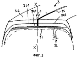
Фиг.2 - схематическое изображение в перспективе вершины пневматической шины в соответствии с настоящим изобретением.Figure 2 is a schematic perspective view of the top of a pneumatic tire in accordance with the present invention.
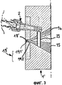
Фиг.3 - изображение в частичном продольном разрезе варианта выполнения устройства в соответствии с настоящим изобретением.Figure 3 - image in partial longitudinal section of an embodiment of a device in accordance with the present invention.
В дальнейшем идентичные элементы устройства, показанные на фиг.1 - 3, будут обозначаться одинаковыми позициями.In the future, identical elements of the device shown in figures 1 to 3 will be denoted by the same positions.
На фиг.1 частично показано устройство для выполнения протектора в невулканизированном состоянии, содержащего два пласта из резиновых смесей А и В, соэкструдированных и содержащих вставку из резиновой смеси С, выполненную путем соэкструзии со смесями А и В.Figure 1 partially shows a device for performing a tread in an unvulcanized state, containing two layers of rubber compounds A and B, coextruded and containing an insert of rubber mixture C, made by coextrusion with mixtures A and B.
На фиг.1 показана экструзионная головка 10 первого основного экструдера 1, обеспечивающего соэкструзию двух невулканизированных резиновых смесей А и В, предназначенного в этом примере для изготовления верхней и нижней частей протектора.Figure 1 shows the extrusion head 10 of the first main extruder 1, providing coextrusion of two unvulcanized rubber compounds A and B, intended in this example for the manufacture of the upper and lower parts of the tread.
Экструзионная головка 10 содержит верхний свод 11 и нижний свод 13, вместе с промежуточным кронштейном 12 ограничивающие два выпускных канала 14 и 15 для подачи каждой из смесей А и В.The extrusion head 10 comprises an upper arch 11 and a lower arch 13, together with an intermediate bracket 12, limiting two
Выпускной канал 15 соединен с первым экструзионным отверстием 17, через которое нагнетается смесь В и которое ограничено стенкой 121 кронштейна 12 и поверхностью 161 барабана 16. В свою очередь, это экструзионное отверстие 17 соединено со вторым экструзионным отверстием 18, в которое нагнетается смесь А, поступающая через выпускной канал 14 таким образом, чтобы смесь В размещались между барабаном 16 и смесью А.The
Экструзионное отверстие 18 ограничено первой и второй стенками, образованными в данном случае соответственно стенкой 111, установленной на своде 11 и принадлежащей экструзионной планке 19, и наружной поверхностью 161 барабана 16. Таким образом, экструзионное отверстие обеспечивает необходимое профилирование состава из двух соэкструдируемых смесей.The
В данном примере экструдер является экструдером с «барабанным мундштуком», в котором первая стенка 111 экструзионной планки 19 является неподвижной, а вторая стенка является подвижной и образована наружной поверхностью 161 барабана 16, взаимодействующего с экструдером. Тем не менее, настоящее изобретение не ограничено применением такого типа экструдера, можно также предусмотреть применение экструдера 1' с так называемым «плоским мундштуком», в котором первая и вторая стенки образованы двумя неподвижными стенками 191' и 192' экструзионной планки 19', как показано на фиг.3. В этом варианте выполнения настоящего изобретения имеется только одно экструзионное отверстие 18.In this example, the extruder is a “drum mouthpiece” extruder in which the first wall 111 of the
С основным экструдером 1 взаимодействует экструдер 2 очень небольшого размера, называемый в обиходе «мини-экструдером», который неподвижно установлен в своде 11. Этот экструдер 2, снабженный шнеком 21 и экструзионной головкой 22, содержит на конце сопло 23, закрепленное на мундштуке мини-экструдера 2 и предназначенное для экструзии, согласно требуемым профилю и направлению, вставки на основе третьей резиновой смеси в каждую невулканизированную и горячую смесь А и В, проходящие по выпускным каналам 14 и 15.A very
Экструзионная головка 22 образует колено 221 таким образом, чтобы экструзионное сопло 23, закрепленное на мундштуке экструзионной головки, проходило через два канала 14 и 15 и кронштейн 12. Таким образом токопроводящая резиновая смесь С, предназначенная для формирования вставки, экструдируется в каждый из потоков смесей А и В. Можно также установить мини-экструдер перпендикулярно оси барабана 16, что позволяет не выполнять экструзионную головку указанного мини-экструдера коленообразной.The extrusion head 22 forms an elbow 221 so that the
Используемая в мини-экструдере 2 экструзионная головка 23 содержит подвижную фильеру, установленную в положении контакта с верхней стенкой 131 свода 13 и пересекающую кронштейн 12, обеспечивая таким образом прохождение смеси С по всей длине сопла.The
На фиг.1 сопло 23 наклонено по отношению к направлению, перпендикулярному концам двух выпускных каналов 14 и 15, соединенных с экструзионным отверстием 18. Такое расположение позволяет вводить резиновую смесь С и, следовательно, выполнять полосу в каждом выпускном канале рядом с экструзионными отверстиями 17 и 18, чтобы избежать чрезмерных деформаций полосы между зоной ее образования и соответствующим экструзионным отверстием. Однако это расположение следует определять в зависимости от определенных параметров, в частности, таких как природа используемых резиновых смесей, условия температуры и давления внутри экструдеров, ширина и природа резиновой смеси С. Поэтому в зависимости от этих критериев сопло может образовывать или не образовывать угол наклона с направлением выпускных каналов и быть более или менее удаленным от экструзионных отверстий.In figure 1, the
В расточном отверстии свода 11 и кронштейна 12 установлено сопло 23 с подвижной фильерой, содержащее на своей цилиндрической поверхности две щели 231, 232 соответствующего сечения на части его высоты таким образом, что каждая щель совпадает с одним из выпускных каналов 14, 15. Контакт между основанием сопла 23 с подвижной фильерой и стенкой 131 свода 13 поддерживается действующим на сечение 230 давлением проводящей смеси. Согласно варианту выполнения настоящего изобретения сопло 23 может быть закреплено непосредственно на стенке 131 свода 13.A
Это устройство позволяет выполнять полосы, ширина которых может изменяться в диапазоне от 0,1 мм до 2 мм, при этом не требуется изменять ширину на уровне оснований двух пластов из резиновых смесей, которые должны контактировать друг с другом. Тем не менее, можно предусмотреть форму щелей, отличающуюся от описанной выше в качестве неограничительного примера. Кроме того, при помощи этого устройства можно, в случае необходимости, осуществлять экструзию смеси С в периодическом режиме в зависимости от поставленной задачи, например для выполнения «прерывистой» полосы.This device allows you to make strips, the width of which can vary in the range from 0.1 mm to 2 mm, while it is not necessary to change the width at the level of the bases of two layers of rubber compounds that must be in contact with each other. However, it is possible to provide for the shape of the slots different from that described above as a non-limiting example. In addition, using this device it is possible, if necessary, to extrude mixture C in a batch mode, depending on the task, for example, to perform an “intermittent” strip.
Размеры такого устройства увеличились очень немного за счет присутствия мини-экструдера. Кроме того, использование только одного сопла для двух каналов облегчает смену смесей, так как для такой смены достаточно убедиться, что сопло пустое. Понятно, что можно выполнять несколько вставок путем закрепления в выпускных каналах соответствующего числа мини-экструдеров, которые могут использоваться последовательно или одновременно в зависимости от поставленной задачи. При необходимости можно также изменять форму щелей на сопле.The dimensions of such a device have increased very slightly due to the presence of a mini-extruder. In addition, the use of only one nozzle for two channels facilitates the change of mixtures, since for such a change it is enough to make sure that the nozzle is empty. It is clear that it is possible to carry out several inserts by fixing in the exhaust channels an appropriate number of mini-extruders that can be used sequentially or simultaneously, depending on the task. If necessary, you can also change the shape of the cracks in the nozzle.
В представленном примере показано выполнение протектора с двумя пластами из резиновых смесей, но настоящее изобретение может применяться также для выполнения протектора, содержащего более двух пластов из резиновых смесей.In the presented example, a tread with two layers of rubber compounds is shown, but the present invention can also be used to make a tread containing more than two layers of rubber compounds.
Таким образом, в соответствии с настоящим изобретением описанное устройство позволяет изготавливать протектор показанной на фиг.2 пневматической шины, содержащий две непроводящие смеси А и В, через которые проходит вставка из проводящей смеси С.Thus, in accordance with the present invention, the described device makes it possible to produce a tread of the pneumatic tire shown in FIG. 2, comprising two non-conductive mixtures A and B, through which an insert from the conductive mixture C passes.
Как показано на фиг.2, пневматическая шина 3 размером 315/80.R.22.5, имеющая низкое сопротивление качению, содержит каркасную арматуру 31, состоящую из металлического слоя, образованного нерастяжимыми металлическими кордными нитями, каландрированными резиновой смесью, выполненной проводящей при помощи сажи, обычно применяемой в смесях в качестве активного наполнителя.As shown in FIG. 2, a pneumatic tire 3 of size 315 / 80.R.22.5, having low rolling resistance, comprises a
Над каркасной арматурой 31 находится арматура вершины 32, состоящая в описанном примере из слоев и/или полуслоев, образованных металлическими кордными нитями. Все кордные нити этой арматуры вершины 32 покрыты одной или несколькими каландровыми резиновыми смесями, проводящими электрические заряды, благодаря присутствию сажи, обычно применяемой в смесях в качестве активного наполнителя.Above the
Внутренний слой 341 и внешний слой 342 протектора 34 выполнены проводящими при помощи резиновой вставки 35 или полосы, имеющей форму окружного кольца, выполненной по всей высоте обоих слоев 341 и 342 и соединяющей поверхность протектора 34, соприкасающуюся с дорожным покрытием, с самым радиально внешним слоем арматуры вершины 32, образованной металлическими кордными нитями, покрытыми резиновой смесью, содержащей в качестве наполнителя обычную проводящую сажу. Эта вставка в представленном примере является единственной и имеет на поверхности протектора очень незначительную осевую ширину е, например, равную 0,5 мм, и ее теоретический центр находится на экваториальной плоскости XX' пневматической шины, а ее рисунок на поверхности 340 контакта между внутренним слоем 341 и самым радиально наружным слоем арматуры вершины 32 является прямолинейным и окружным. Центр вставки 35 может быть смещен, в частности, в случае наличия на протекторе центральной канавки; может быть также выполнено две вставки, например, расположенные симметрично по отношению к экваториальной плоскости, или больше двух вставок, которые в любом случае расположены аксиально таким образом, чтобы обеспечить контакт с дорожным покрытием независимо от степени износа протектора. Можно также предусмотреть, чтобы вставка имела форму кольца, непрерывного или прерывистого в окружном направлении.The
Резиновую смесь, обеспечивающую проводящее электрические заряды соединение 11, получают на основе натурального каучука и/или синтетических каучуков, обычно используемых для изготовления пневматических шин и, в частности, протекторов, и она содержит в качестве активного наполнителя проводящую сажу, обычно применяемую при производстве пневматических шин.The rubber composition providing the electrical conductive compound 11 is prepared on the basis of natural rubber and / or synthetic rubbers commonly used for the manufacture of pneumatic tires and, in particular, treads, and it contains conductive carbon black as an active filler commonly used in the manufacture of pneumatic tires .
Не выходя за рамки изобретения, можно применять способ и устройство в соответствии с настоящим изобретением для включения в резиновые смеси вставок без проводящих свойств, например для включения в черные резиновые смеси одной или нескольких цветных вставок.Without going beyond the scope of the invention, it is possible to apply the method and device in accordance with the present invention for incorporating inserts into the rubber compounds without conductive properties, for example, for incorporating one or more colored inserts into black rubber compounds.
Claims (9)
Applications Claiming Priority (2)
| Application Number | Priority Date | Filing Date | Title |
|---|---|---|---|
| FR0106489 | 2001-05-16 | ||
| FR0106489 | 2001-05-16 |
Publications (2)
| Publication Number | Publication Date |
|---|---|
| RU2003105224A RU2003105224A (en) | 2004-06-20 |
| RU2286255C2 true RU2286255C2 (en) | 2006-10-27 |
Family
ID=8863374
Family Applications (1)
| Application Number | Title | Priority Date | Filing Date |
|---|---|---|---|
| RU2003105224/12A RU2286255C2 (en) | 2001-05-16 | 2002-05-15 | Device for coextrusion of rubber mixes |
Country Status (12)
| Country | Link |
|---|---|
| US (1) | US6994817B2 (en) |
| EP (1) | EP1448355B1 (en) |
| JP (1) | JP4374192B2 (en) |
| KR (1) | KR20030020371A (en) |
| CN (1) | CN1238176C (en) |
| AT (1) | ATE414601T1 (en) |
| BR (1) | BR0205350B1 (en) |
| CA (1) | CA2420772A1 (en) |
| DE (1) | DE60229974D1 (en) |
| PL (1) | PL363908A1 (en) |
| RU (1) | RU2286255C2 (en) |
| WO (1) | WO2002092322A1 (en) |
Cited By (3)
| Publication number | Priority date | Publication date | Assignee | Title |
|---|---|---|---|---|
| RU2454326C2 (en) * | 2007-06-27 | 2012-06-27 | Секисуй Кемикал Ко., Лтд. | Device and method of producing complex intermediate layer for triplex |
| RU2569084C2 (en) * | 2010-07-16 | 2015-11-20 | Эксонмобил Кемикэл Пейтентс Инк. | Extrusion of adhesive for laminates from dynamically cured thermoplastic elastomer |
| RU2662524C2 (en) * | 2013-06-10 | 2018-07-26 | Блю Солюшнз | Spinning jet for the film manufacturing by extrusion |
Families Citing this family (22)
| Publication number | Priority date | Publication date | Assignee | Title |
|---|---|---|---|---|
| DE60218556T2 (en) * | 2001-03-12 | 2007-11-22 | Bridgestone Corp. | tires |
| KR100513240B1 (en) * | 2003-11-04 | 2005-09-07 | 금호타이어 주식회사 | Molding Extruder Die set of the Tire having a slope conductive ring |
| RU2381911C2 (en) * | 2005-03-16 | 2010-02-20 | Бриджстоун Корпорейшн | Air tire |
| US8062017B2 (en) * | 2008-10-13 | 2011-11-22 | The Goodyear Tire & Rubber Co | Splice bar for tire tread extrusion apparatus |
| US8016580B2 (en) * | 2009-01-28 | 2011-09-13 | The Goodyear Tire & Rubber Company | Assembly and a method for extruding a tire component |
| US10253181B2 (en) * | 2009-09-07 | 2019-04-09 | Kuraray Co., Ltd. | Reflector for LED and light-emitting device equipped with same |
| NL2006420C2 (en) * | 2011-03-18 | 2012-09-19 | Apollo Vredestein Bv | Method of manufacturing an antistatic vehicle tire and vehicle tire obtainable by the method. |
| NL2006729C2 (en) * | 2011-05-06 | 2012-11-08 | Apollo Vredestein Bv | Method and device for manufacturing an antistatic vehicle tire. |
| NL2006728C2 (en) * | 2011-05-06 | 2012-11-08 | Apollo Vredestein Bv | Method and device for manufacturing an antistatic vehicle tire. |
| US9085104B2 (en) | 2011-07-20 | 2015-07-21 | Nordson Corporation | Sculpted extrusion die |
| DE102012104691A1 (en) * | 2012-05-31 | 2013-12-05 | Continental Reifen Deutschland Gmbh | Process for producing a mixture web and method for producing a material web from two mixing webs |
| DE102015202171A1 (en) * | 2015-02-06 | 2016-08-11 | Continental Reifen Deutschland Gmbh | Method and device for producing a multilayer composite slug strip |
| FR3046105B1 (en) | 2015-12-23 | 2017-12-22 | Michelin & Cie | COEXTRUSION HEAD OF A COMPLEX RUBBER PROFILE INTENDED FOR THE MANUFACTURE OF A PNEUMATIC |
| FR3046104B1 (en) * | 2015-12-23 | 2017-12-22 | Michelin & Cie | METHOD FOR COEXTRUSION OF A COMPLEX RUBBER PROFILE FOR THE MANUFACTURE OF A PNEUMATIC |
| FR3060435A1 (en) | 2016-12-20 | 2018-06-22 | Compagnie Generale Des Etablissements Michelin | COEXTRUSION HEAD OF A COMPLEX RUBBER PROFILE INTENDED FOR THE MANUFACTURE OF A PNEUMATIC |
| FR3060436A1 (en) | 2016-12-20 | 2018-06-22 | Compagnie Generale Des Etablissements Michelin | METHOD FOR COEXTRUSION OF A COMPLEX RUBBER PROFILE FOR THE MANUFACTURE OF A PNEUMATIC |
| US11440235B2 (en) * | 2017-06-30 | 2022-09-13 | Compagnie Generale Des Etablissements Michelin | Extrusion head with channels for producing inserts in a profiled band for manufacturing a pneumatic tire and corresponding extrusion method |
| FR3071760B1 (en) | 2017-10-04 | 2021-01-22 | Michelin & Cie | EXTRUSION HEAD OF A COMPLEX PROFILE INCLUDING AN INSERT IN A HIGHLY ELASTIC MIXTURE |
| FR3072896A1 (en) | 2017-10-27 | 2019-05-03 | Compagnie Generale Des Etablissements Michelin | HEAD OF EXTRUSION OF A COMPLEX PROFILE FORMED OF JUXTAPOSES PROFILES |
| CN108215118A (en) * | 2018-01-25 | 2018-06-29 | 正新橡胶(中国)有限公司 | A kind of extruder die for producing conductive tyre |
| WO2022018979A1 (en) * | 2020-07-22 | 2022-01-27 | 株式会社神戸製鋼所 | Metal member, and method for processing rubber material using device comprising said metal member |
| FR3117398B1 (en) * | 2020-12-16 | 2023-10-06 | Continental Reifen Deutschland Gmbh | Improved extrusion plant for the manufacture of profile strips |
Family Cites Families (18)
| Publication number | Priority date | Publication date | Assignee | Title |
|---|---|---|---|---|
| US2342576A (en) | 1941-08-01 | 1944-02-22 | Wingfoot Corp | Tire construction |
| DE3325017C2 (en) | 1983-07-11 | 1985-11-28 | Continental Gummi-Werke Ag, 3000 Hannover | Press head for the production of flat, coherent profile strands from plastic rubber or plastic mixtures of various compositions |
| US4539169A (en) | 1983-07-29 | 1985-09-03 | The Goodyear Tire & Rubber Company | Apparatus and method for forming a co-extrusion from extruded strips |
| US5017118A (en) * | 1989-06-16 | 1991-05-21 | The Goodyear Tire & Rubber Company | Apparatus for forming a coextrusion from extruded strips |
| FR2673187B1 (en) | 1991-02-25 | 1994-07-01 | Michelin & Cie | RUBBER COMPOSITION AND TIRE COVERS BASED ON SAID COMPOSITION. |
| FR2700291A1 (en) | 1993-01-08 | 1994-07-13 | Michelin & Cie | Extrusion apparatus and extrusion method for raw rubber mixtures. |
| IT1264990B1 (en) | 1993-12-14 | 1996-10-17 | Pirelli | ANTISTATIC TIRE WITH LOW CARBON BLACK COMPOUNDS |
| CA2140999A1 (en) | 1994-11-07 | 1996-05-08 | Jennifer Leigh Gabor | Triplex tread |
| US5928679A (en) | 1995-07-13 | 1999-07-27 | Sumitomo Rubber Industries, Ltd. | Elastomeric extruding apparatus |
| FR2759946B1 (en) | 1997-02-24 | 1999-04-09 | Michelin & Cie | MULTIPLE NON-CONDUCTIVE TIRES |
| IT1290520B1 (en) * | 1997-04-03 | 1998-12-04 | Pirelli | EXTRUSION METHOD AND APPARATUS FOR MAKING TREAD BANDS FOR VEHICLE TIRES |
| ES2259198T3 (en) | 1997-08-07 | 2006-09-16 | Bridgestone Corporation | PNEUMATIC COVER AND MANUFACTURING METHOD OF THE SAME. |
| US6294119B1 (en) * | 1997-12-26 | 2001-09-25 | Bridgestone Corporation | Production of unvulcanized tread rubber for pneumatic tires |
| KR100649908B1 (en) * | 1998-02-26 | 2006-11-27 | 꽁빠니 제네랄 드 에따블리세망 미쉘린-미쉘린 에 씨 | Electrically conductive tyre and apparatus for extruding sections made conductive |
| JP3863298B2 (en) | 1998-08-05 | 2006-12-27 | 株式会社ブリヂストン | Unvulcanized rubber extrusion method |
| ES2238242T3 (en) * | 1999-11-23 | 2005-09-01 | Societe De Technologie Michelin | APPARATUS FOR THE COEXTRUSION OF RUBBER BLENDS. |
| DE60218556T2 (en) * | 2001-03-12 | 2007-11-22 | Bridgestone Corp. | tires |
| US6746227B2 (en) * | 2001-06-19 | 2004-06-08 | The Goodyear Tire & Rubber Company | Tire tread die |
-
2002
- 2002-05-15 DE DE60229974T patent/DE60229974D1/en not_active Expired - Lifetime
- 2002-05-15 BR BRPI0205350-0A patent/BR0205350B1/en not_active IP Right Cessation
- 2002-05-15 CA CA002420772A patent/CA2420772A1/en not_active Abandoned
- 2002-05-15 JP JP2002589239A patent/JP4374192B2/en not_active Expired - Fee Related
- 2002-05-15 EP EP02750930A patent/EP1448355B1/en not_active Expired - Lifetime
- 2002-05-15 RU RU2003105224/12A patent/RU2286255C2/en not_active IP Right Cessation
- 2002-05-15 PL PL02363908A patent/PL363908A1/en unknown
- 2002-05-15 WO PCT/EP2002/005333 patent/WO2002092322A1/en active Application Filing
- 2002-05-15 AT AT02750930T patent/ATE414601T1/en not_active IP Right Cessation
- 2002-05-15 CN CNB028016939A patent/CN1238176C/en not_active Expired - Fee Related
- 2002-05-15 KR KR10-2003-7000602A patent/KR20030020371A/en not_active Application Discontinuation
-
2003
- 2003-02-13 US US10/366,529 patent/US6994817B2/en not_active Expired - Lifetime
Cited By (3)
| Publication number | Priority date | Publication date | Assignee | Title |
|---|---|---|---|---|
| RU2454326C2 (en) * | 2007-06-27 | 2012-06-27 | Секисуй Кемикал Ко., Лтд. | Device and method of producing complex intermediate layer for triplex |
| RU2569084C2 (en) * | 2010-07-16 | 2015-11-20 | Эксонмобил Кемикэл Пейтентс Инк. | Extrusion of adhesive for laminates from dynamically cured thermoplastic elastomer |
| RU2662524C2 (en) * | 2013-06-10 | 2018-07-26 | Блю Солюшнз | Spinning jet for the film manufacturing by extrusion |
Also Published As
| Publication number | Publication date |
|---|---|
| BR0205350A (en) | 2003-04-22 |
| JP2004525012A (en) | 2004-08-19 |
| DE60229974D1 (en) | 2009-01-02 |
| BR0205350B1 (en) | 2010-10-19 |
| EP1448355A1 (en) | 2004-08-25 |
| US20030136498A1 (en) | 2003-07-24 |
| JP4374192B2 (en) | 2009-12-02 |
| ATE414601T1 (en) | 2008-12-15 |
| CA2420772A1 (en) | 2002-11-21 |
| KR20030020371A (en) | 2003-03-08 |
| US6994817B2 (en) | 2006-02-07 |
| WO2002092322A1 (en) | 2002-11-21 |
| CN1463220A (en) | 2003-12-24 |
| CN1238176C (en) | 2006-01-25 |
| EP1448355B1 (en) | 2008-11-19 |
| PL363908A1 (en) | 2004-11-29 |
Similar Documents
| Publication | Publication Date | Title |
|---|---|---|
| RU2286255C2 (en) | Device for coextrusion of rubber mixes | |
| RU2254239C2 (en) | Method of production of an element for a pneumatic tire based on rubber mixtures and a device for its realization | |
| US6834693B1 (en) | Electrically conductive tire and extrusion equipment for a section with a conductive insert | |
| EP1175992B1 (en) | Method of producing a tread for a pneumatic tire using an electrically conductive rubber material | |
| US6951233B1 (en) | Electrically conductive tire and apparatus and process for extruding elements which have been made conductive | |
| US8167015B2 (en) | Method of manufacturing pneumatic tire and manufacturing pneumatic tire | |
| US20120152418A1 (en) | Manufacturing method of pneumatic tire and pneumatic tire | |
| KR100649908B1 (en) | Electrically conductive tyre and apparatus for extruding sections made conductive | |
| EP2465711B1 (en) | Pneumatic tire and manufacturing method of the same | |
| JP5907703B2 (en) | Pneumatic tire manufacturing method | |
| RU2000124412A (en) | ELECTRIC WIRED PNEUMATIC TIRE AND DEVICE FOR EXTRUSION OF PROFILED ELEMENTS COMPLETED BY ELECTRIC WIRES | |
| JPH11240081A (en) | Manufacture of unvulcanized tread rubber for tire and pneumatic tire | |
| JP5611861B2 (en) | Pneumatic tire manufacturing method and pneumatic tire | |
| EP2520421B1 (en) | Method and device for manufacturing an antistatic vehicle tire | |
| JP2000318016A (en) | Rubber extruding apparatus | |
| JP3863298B2 (en) | Unvulcanized rubber extrusion method | |
| JP5970179B2 (en) | Pneumatic tire manufacturing method and pneumatic tire | |
| EP1207033B1 (en) | Method and device for producing a two-part tire layer | |
| EP1878592B1 (en) | Method for manufacturing a vehicle pneumatic tyre | |
| KR100253983B1 (en) | Tyre cap tread |
Legal Events
| Date | Code | Title | Description |
|---|---|---|---|
| PC43 | Official registration of the transfer of the exclusive right without contract for inventions |
Effective date: 20121220 |
|
| MM4A | The patent is invalid due to non-payment of fees |
Effective date: 20190516 |