RU2284967C1 - Bioenergetic installation - Google Patents
Bioenergetic installation Download PDFInfo
- Publication number
- RU2284967C1 RU2284967C1 RU2005117017/12A RU2005117017A RU2284967C1 RU 2284967 C1 RU2284967 C1 RU 2284967C1 RU 2005117017/12 A RU2005117017/12 A RU 2005117017/12A RU 2005117017 A RU2005117017 A RU 2005117017A RU 2284967 C1 RU2284967 C1 RU 2284967C1
- Authority
- RU
- Russia
- Prior art keywords
- biogas
- biomass
- production
- engine
- energy
- Prior art date
Links
Images
Classifications
-
- Y—GENERAL TAGGING OF NEW TECHNOLOGICAL DEVELOPMENTS; GENERAL TAGGING OF CROSS-SECTIONAL TECHNOLOGIES SPANNING OVER SEVERAL SECTIONS OF THE IPC; TECHNICAL SUBJECTS COVERED BY FORMER USPC CROSS-REFERENCE ART COLLECTIONS [XRACs] AND DIGESTS
- Y02—TECHNOLOGIES OR APPLICATIONS FOR MITIGATION OR ADAPTATION AGAINST CLIMATE CHANGE
- Y02P—CLIMATE CHANGE MITIGATION TECHNOLOGIES IN THE PRODUCTION OR PROCESSING OF GOODS
- Y02P60/00—Technologies relating to agriculture, livestock or agroalimentary industries
- Y02P60/12—Technologies relating to agriculture, livestock or agroalimentary industries using renewable energies, e.g. solar water pumping
Landscapes
- Processing Of Solid Wastes (AREA)
- Treatment Of Sludge (AREA)
Abstract
Description
Изобретение относится к сельскому хозяйству, а именно к установкам для переработки органических отходов сельскохозяйственного производства в анаэробных условиях, и может быть использовано для производства биогаза из органических отходов.The invention relates to agriculture, and in particular to installations for the processing of organic agricultural waste under anaerobic conditions, and can be used for the production of biogas from organic waste.
Известна установка для производства биогаза из органических отходов, в частности, предусматривающая для обогрева сбраживаемого субстрата использование солнечной энергии и содержащая метантенк, солнечные коллекторы, теплообменники, газгольдер, компрессор, вентили, котел, насосы, отстойник и регулирующие клапаны (Амерханов Р.А., Бессараб А.С., Драганов Б.Х., Рудобашта С.П., Шишко Г.Г. Теплоэнергетические установки и системы сельского хозяйства. - М.: Колос-Пресс, 2002, с.269, рис.11.51).A known installation for the production of biogas from organic waste, in particular, providing for the use of solar energy for heating a fermentable substrate, containing a digester, solar collectors, heat exchangers, a gas holder, compressor, valves, a boiler, pumps, a sump and control valves (Amerkhanov R.A., Bessarab A.S., Draganov B.Kh., Rudobashta S.P., Shishko G.G. Thermal power plants and agricultural systems. - M .: Kolos-Press, 2002, p. 269, Fig. 11.51).
Известен также биоэнергокомлекс, содержащий метантенк, коллектор солнечной энергии, нагреватель сбраживаемой массы (а.с. СССР №1745707, БИ №25, 1992).Also known is a bioenergy complex containing a digester, a solar energy collector, a fermented mass heater (AS USSR No. 1745707, BI No. 25, 1992).
Известен биоэнергокомплекс с использованием солнечной энергии для обогрева сбраживаемой биомассы, содержащий метантенк с системой загрузки и выгрузки биомассы, солнечный коллектор с трубопроводами (а.с. СССР №1527191, 06.07.1987).Known bioenergy complex using solar energy for heating fermentable biomass, containing a digester with a biomass loading and unloading system, a solar collector with pipelines (AS USSR No. 1527191, 07/06/1987).
Наиболее близким по технической сущности к предлагаемой установке является биоэнергетическая установка, содержащая метантенк с водяной рубашкой, теплоизоляцией, мешалкой, загрузочным и выгрузочным патрубками, трубопроводы для отвода биогаза, электроводонагреватель, трубопроводы подачи биогаза и газгольдер (а.с. №1733407, МКИ С 02 F 11/04, опубликовано 15.05.1992).The closest in technical essence to the proposed installation is a bioenergy installation containing a digester with a water jacket, heat insulation, stirrer, loading and unloading pipes, pipelines for biogas removal, an electric heater, pipelines for supplying biogas and a gas holder (AS No. 1733407, MKI S 02 F 11/04, published 05/15/1992).
Недостатком известного биоэнергокомплекса является невозможность обеспечения стабильного обогрева сбраживаемого субстрата и обеспечения гарантированного минимума энергоснабжения локальных энергопотребителей в условиях отсутствия централизованного источника электрической энергии, поскольку количество теплоты, поступающей на землю с солнечным излучением, резко колеблется в зависимости от местных климатических условий.A disadvantage of the known bioenergy complex is the impossibility of providing stable heating of the fermented substrate and ensuring a guaranteed minimum power supply to local energy consumers in the absence of a centralized source of electrical energy, since the amount of heat entering the earth with solar radiation fluctuates sharply depending on local climatic conditions.
Задачей предлагаемого изобретения является обеспечение стабильного обогрева сбраживаемого субстрата и гарантированного минимума автономного энергоснабжения локальных потребителей в условиях отсутствия централизованного источника электрической энергии.The objective of the invention is to provide stable heating of the fermentable substrate and a guaranteed minimum of autonomous power supply to local consumers in the absence of a centralized source of electrical energy.
В результате использования предлагаемого изобретения повышается КПД и надежность работы биоэнергетической установки для получения биогаза в условиях отсутствия централизованного источника электрической энергии, появляется возможность прямого преобразования тепловой энергии сжигаемого биогаза в электрическую энергию и обеспечения гарантированного минимума энергоснабжения локальных потребителей.As a result of the use of the present invention, the efficiency and reliability of a bioenergy plant for producing biogas in the absence of a centralized source of electric energy are increased, it becomes possible to directly convert the thermal energy of the biogas burned into electrical energy and to ensure a guaranteed minimum energy supply for local consumers.
Вышеуказанный технический результат достигается тем, что биоэнергетическая установка, содержащая метантенк с водяной рубашкой, теплоизоляцией, мешалкой, загрузочным и выгрузочным патрубками, трубопроводы для отвода биогаза, электроводонагреватель, трубопроводы подачи биогаза и газгольдер, снабжена гелиоколлектором, электроводонагревателем и двигателем Стирлинга в виде термомеханического генератора с расположенной со стороны днища двигателя биогазовой горелкой, которая соединена с трубопроводом для подачи биогаза из газгольдера, при этом в двигателе Стирлинга тепловая энергия сжигаемого в биогазовой горелке биогаза преобразовывается в электрическую энергию и используется для обогрева сбраживаемой в метантенке биомассы до необходимой температуры и обеспечения непрерывной работы системы в периоды отсутствия поступления солнечного излучения.The above technical result is achieved in that a bioenergy installation containing a digester with a water jacket, heat insulation, mixer, loading and unloading pipes, pipelines for biogas removal, an electric heater, biogas supply pipes and a gas holder, is equipped with a solar collector, an electric heater and a Stirling engine with a biogas burner located on the bottom side of the engine, which is connected to a pipeline for supplying biogas from the gas tank, at the same time, in the Stirling engine, the thermal energy of the biogas burned in the biogas burner is converted into electrical energy and is used to heat the biomass fermented in the digester to the required temperature and to ensure continuous operation of the system during periods when there is no solar radiation.
Вырабатываемая двигателем Стирлинга в виде термомеханического генератора электроэнергия используется частично для обогрева метантенка через электроводонагреватель, остальная часть вырабатываемой электрической энергии идет для обеспечения гарантированного минимума энергоснабжения локальных потребителей.Electricity generated by the Stirling engine in the form of a thermomechanical generator is partially used to heat the digester through an electric water heater, the rest of the generated electric energy is used to ensure a guaranteed minimum power supply to local consumers.
Сущность изобретения поясняется фиг.1 и фиг.2.The invention is illustrated in figure 1 and figure 2.
На фиг.1 представлена технологическая схема автономной энергетической установки для получения биогаза и электрической энергии.Figure 1 presents the technological scheme of an autonomous power plant for biogas and electric energy.
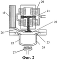
На фиг.2 представлена конструкция термомеханического генератора - двигателя Стирлинга в сочетании с биогазовой горелкой.Figure 2 presents the design of a thermomechanical generator - a Stirling engine in combination with a biogas burner.
Установка содержит газгольдер 1, трубопровод отвода биогаза 2, метантенк 3 с водяной рубашкой 4, мешалкой 5 и теплоизоляцией 6, загрузочным 7 и выгрузочным 8 патрубками, бак-аккумулятор 9 и вентиль 10 горячей воды, плоский гелиоколлектор 11, трубопроводы воды 12 и 13, электроводонагреватель 14, биогазовую горелку 15 и трубопровод подачи биогаза 16, двигатель Стирлинга 17 и систему электрического соединения 18.The installation comprises a gas holder 1, a biogas discharge pipe 2, a digester 3 with a water jacket 4, a mixer 5 and heat insulation 6, a loading 7 and an unloading 8 pipes, an accumulator tank 9 and a hot water valve 10, a flat solar collector 11, water pipelines 12 and 13, an electric water heater 14, a biogas burner 15 and a biogas supply pipe 16, a Stirling engine 17 and an electrical connection system 18.
Двигатель Стирлинга, являющийся тепловым двигателем, выполнен в виде термомеханического генератора, который в отличие от обычного двигателя Стирлинга с рабочим и вытеснительными поршнями (Кудрин О.И. Солнечные высокотемпературные космические энергодвигательные установки. Под ред. В.П.Белякова. - М.: Машиностроение, 1987. - 248 с.) имеет следующие особенности:The Stirling engine, which is a heat engine, is made in the form of a thermomechanical generator, which, in contrast to the conventional Stirling engine with working and displacement pistons (O. Kudrin, Solar high-temperature space power propulsion systems. Edited by V.P. Belyakov. - M .: Engineering, 1987. - 248 p.) Has the following features:
- отсутствие кривошипно-шатунного механизма и полная изоляция обоих торцов цилиндра, поскольку агрегат не содержит ни шатунов, ни каких-либо других рычагов, связанных с поршнями;- the lack of a crank mechanism and the complete isolation of both ends of the cylinder, since the unit does not contain either connecting rods or any other levers associated with the pistons;
- рабочий поршень здесь заменен металлической диафрагмой.- the working piston is replaced by a metal diaphragm.
Используемая в биоэнергетической установке конструкция термомеханического генератора в сочетании с биогазовой горелкой представлена на фиг.2. и содержит радиатор 19, обмотки 20 и якорь 21 генератора, диафрагму 22, пружину 23, цилиндр 24, вытеснитель 25, охлаждающий змеевик 26 и биогазовую горелку 27.The design of a thermomechanical generator used in a bioenergy installation in combination with a biogas burner is shown in FIG. 2. and contains a
Рабочий цикл термомеханического генератора полностью идентичен циклу двигателя Стирлинга с рабочим и вытеснительными поршнями, за исключением того, что здесь вытеснитель 25 приводится в действие пружиной 23, расположенной между ним и корпусом цилиндра 24. Замкнутый металлический цилиндр, содержащий рабочее тело двигателя, нагревается со стороны днища биогазовой горелкой 27 и охлаждается с внешней стороны диафрагмы 22, расположенной в верхней части цилиндра, охлаждающим змеевиком 26 с радиатором 19. Металлическая диафрагма 22, изготавливаемая из нержавеющей стали и установленная в термомеханическом генераторе вместо рабочего поршня, перемещается в цилиндре 24 вверх и вниз. Эта диафрагма колеблется под действием изменяющегося давления рабочего тела в цилиндре. С диафрагмой жестко связан якорь (постоянный магнит) 21, который совершает колебательные движения в обмотке 20 генератора, возбуждая электрический ток. Необходимость установки пружины для приведения в действие вытеснителя объясняется тем, что диафрагма совершает колебания с амплитудой, не превышающей нескольких миллиметров. Действие пружины, соединенной с вытеснителем, дает возможность системе совешать резонансные колебания при частоте, равной частоте собственных колебаний системы. Частота колебаний регулируется подбором пружины и движущихся масс, что позволяет "подстроиться" под любую частоту в системе электроснабжения.The working cycle of the thermomechanical generator is completely identical to the cycle of the Stirling engine with the working and displacement pistons, except that here the
Работа биоэнергетической установки согласно технологической схеме, представленной на фиг.1, осуществляется следующим образом.The bioenergy installation according to the technological scheme presented in figure 1, is as follows.
Исходная биомасса в виде органических отходов животноводства через загрузочный патрубок 7 загружается в метантенк 3 с водяной рубашкой 4, мешалкой 5 и теплоизоляцией 6.The original biomass in the form of organic animal waste through a loading pipe 7 is loaded into a digester 3 with a water jacket 4, a mixer 5 and thermal insulation 6.
Необходимый температурный режим процесса анаэробного метанового сбраживания биомассы в метантенке 3 обеспечивается посредством преобразованной в тепловую энергию в гелиоколлекторе 11 энергии солнечного излучения: нагреваемая в гелиоколлекторе 11 и накапливаемая в баке-аккумуляторе 9 вода через вентиль 10 горячей воды и трубопровод воды 12 поступает в водяную рубашку 4 метантенка 3.The required temperature regime of the process of anaerobic methane digestion of biomass in the digester 3 is provided by solar radiation energy converted into thermal energy in the solar collector 11: the water heated in the solar collector 11 and accumulated in the storage tank 9 through the hot water valve 10 and the water pipe 12 enters the water jacket 4 digester 3.
В процессе анаэробной бактериальной деструкции органических веществ биомассы в метантенке 3 выделяется биогаз, который через трубопровод отвода биогаза 2 поступает и накапливается в газгольдере 1.In the process of anaerobic bacterial destruction of organic biomass substances in digester 3, biogas is released, which enters and accumulates in the gas tank 1 through the biogas exhaust pipe 2.
Далее осуществляется утилизация получаемого биогаза: часть получаемого биогаза используется путем непосредственного сжигания в бытовых отопительных газовых приборах; часть его идет по мере необходимости, в периоды отсутствия поступления солнечного излучения, по трубопроводу для подачи биогаза 16 для сжигания в биогазовой горелке 15, расположенной со стороны днища двигателя Стирлинга 17. В двигателе Стирлинга в виде термомеханического генератора тепловая энергия сжигаемого в биогазовой горелке биогаза преобразовывается в электрическую энергию. Полученная таким образом электрическая энергия через электроводонагреватель 14 и трубопроводы воды 13 используется для обогрева сбраживаемой в метантенке биомассы до необходимой температуры и поддерживания ее в постоянном режиме. Далее процесс выработки и использования биогаза и электроэнергии продолжается, как указано выше.Further, the biogas produced is disposed of: part of the biogas produced is used by direct combustion in household gas heating appliances; part of it goes, as necessary, during periods when there is no solar radiation, through a pipeline for supplying biogas 16 for combustion in a biogas burner 15 located on the side of the bottom of the Stirling engine 17. In the Stirling engine in the form of a thermomechanical generator, the thermal energy of the biogas burned in a biogas burner is converted into electrical energy. Thus obtained electrical energy through an electric heater 14 and water pipelines 13 is used to heat the biomass fermented in the digester to the required temperature and maintain it in a constant mode. Further, the process of generation and use of biogas and electricity continues, as described above.
Учитывая, что в настоящее время в условиях высокой стоимости производства и распределения электроэнергии особое внимание привлекают местные топливно-энергетические ресурсы, применение биоэнергетической установки с двигателем Стирлинга в виде термомеханического генератора может существенно повысить уровень энергообеспечения потребителей в условиях отсутствия централизованного энергоснабжения.Given that at present, in the context of the high cost of production and distribution of electricity, local fuel and energy resources are of particular interest, the use of a bioenergy plant with a Stirling engine in the form of a thermomechanical generator can significantly increase the energy supply level of consumers in the absence of a centralized energy supply.
Claims (1)
Priority Applications (1)
| Application Number | Priority Date | Filing Date | Title |
|---|---|---|---|
| RU2005117017/12A RU2284967C1 (en) | 2005-06-03 | 2005-06-03 | Bioenergetic installation |
Applications Claiming Priority (1)
| Application Number | Priority Date | Filing Date | Title |
|---|---|---|---|
| RU2005117017/12A RU2284967C1 (en) | 2005-06-03 | 2005-06-03 | Bioenergetic installation |
Publications (1)
| Publication Number | Publication Date |
|---|---|
| RU2284967C1 true RU2284967C1 (en) | 2006-10-10 |
Family
ID=37435554
Family Applications (1)
| Application Number | Title | Priority Date | Filing Date |
|---|---|---|---|
| RU2005117017/12A RU2284967C1 (en) | 2005-06-03 | 2005-06-03 | Bioenergetic installation |
Country Status (1)
| Country | Link |
|---|---|
| RU (1) | RU2284967C1 (en) |
Cited By (8)
| Publication number | Priority date | Publication date | Assignee | Title |
|---|---|---|---|---|
| RU2448913C2 (en) * | 2010-01-12 | 2012-04-27 | Общество с ограниченной ответственностью "Черноморская Энергетическая Компания " | Bioenergetical complex ''biocheck'' |
| CN102641883A (en) * | 2012-04-28 | 2012-08-22 | 安阳艾尔旺新能源环境有限公司 | Garbage treatment device |
| RU2499954C1 (en) * | 2012-06-06 | 2013-11-27 | Общество с ограниченной ответственностью "КИВИ Энерджи" | Method to produce thermal and electric energy from renewable sources |
| RU2543361C2 (en) * | 2010-09-29 | 2015-02-27 | Ухань Каиди Инжиниринг Технолоджи Рисоч Институтеко., Лтд. | Method of electric power generation from sun energy and system using biofuel boiler as additional heat source |
| MD4431C1 (en) * | 2015-05-07 | 2017-03-31 | Государственный Университет Молд0 | Biogas plant with renewable energy source systems |
| RU2688356C1 (en) * | 2017-12-27 | 2019-05-21 | федеральное государственное бюджетное образовательное учреждение высшего образования "Алтайский государственный технический университет им. И.И. Ползунова" (АлтГТУ) | Biogas plant for processing of organic wastes into biogas and biofertilizers |
| RU2734456C1 (en) * | 2019-11-18 | 2020-10-16 | Яхя Алиевич Дибиров | Autonomous solar biogas plant |
| RU2785600C2 (en) * | 2021-04-05 | 2022-12-09 | Федеральное государственное бюджетное учреждение науки Объединенный институт высоких температур Российской академии наук (ОИВТ РАН) | Helio-biogas complex |
-
2005
- 2005-06-03 RU RU2005117017/12A patent/RU2284967C1/en not_active IP Right Cessation
Cited By (8)
| Publication number | Priority date | Publication date | Assignee | Title |
|---|---|---|---|---|
| RU2448913C2 (en) * | 2010-01-12 | 2012-04-27 | Общество с ограниченной ответственностью "Черноморская Энергетическая Компания " | Bioenergetical complex ''biocheck'' |
| RU2543361C2 (en) * | 2010-09-29 | 2015-02-27 | Ухань Каиди Инжиниринг Технолоджи Рисоч Институтеко., Лтд. | Method of electric power generation from sun energy and system using biofuel boiler as additional heat source |
| CN102641883A (en) * | 2012-04-28 | 2012-08-22 | 安阳艾尔旺新能源环境有限公司 | Garbage treatment device |
| RU2499954C1 (en) * | 2012-06-06 | 2013-11-27 | Общество с ограниченной ответственностью "КИВИ Энерджи" | Method to produce thermal and electric energy from renewable sources |
| MD4431C1 (en) * | 2015-05-07 | 2017-03-31 | Государственный Университет Молд0 | Biogas plant with renewable energy source systems |
| RU2688356C1 (en) * | 2017-12-27 | 2019-05-21 | федеральное государственное бюджетное образовательное учреждение высшего образования "Алтайский государственный технический университет им. И.И. Ползунова" (АлтГТУ) | Biogas plant for processing of organic wastes into biogas and biofertilizers |
| RU2734456C1 (en) * | 2019-11-18 | 2020-10-16 | Яхя Алиевич Дибиров | Autonomous solar biogas plant |
| RU2785600C2 (en) * | 2021-04-05 | 2022-12-09 | Федеральное государственное бюджетное учреждение науки Объединенный институт высоких температур Российской академии наук (ОИВТ РАН) | Helio-biogas complex |
Similar Documents
| Publication | Publication Date | Title |
|---|---|---|
| RU2284967C1 (en) | Bioenergetic installation | |
| KR101821315B1 (en) | solar thermal and BIGCC-integrated combined power generation system | |
| KR101254622B1 (en) | Energy regeneration system | |
| RU2013119272A (en) | METHOD FOR ELECTRICITY PRODUCTION FROM SOLAR ENERGY AND SYSTEM USING BIOFUEL BOILER AS AN EXTRA HEAT SOURCE | |
| CN108612634A (en) | Solar energy is provided multiple forms of energy to complement each other thermal electric generator | |
| Crema et al. | Development of a pellet boiler with Stirling engine for m-CHP domestic application | |
| CN103321861A (en) | Dish solar power-heat cogeneration system based on singe-screw expander and molten salt | |
| Iodice et al. | Comparative exergetic analysis of solar integration and regeneration in steam power plants | |
| Singh et al. | Biogas driven multigeneration integrated with simultaneous charging-discharging type thermal energy storage system | |
| RU166736U1 (en) | HELIOBIOGAS GAS INSTALLATION | |
| CN101619714B (en) | Biomass thermal noise generating system | |
| RU96859U1 (en) | BIOENERGY COMPLEX | |
| RU65044U1 (en) | BIOENERGOKOMPLEKS | |
| RU84919U1 (en) | HEAT AND POWER INSTALLATION | |
| CN201277065Y (en) | Biomass generator | |
| Szewczyk et al. | Application of biomass-powered Stirling engines in cogenerative systems | |
| RU2253211C1 (en) | Bioenergetic apparatus | |
| RU2008129555A (en) | METHOD OF ELECTRIC POWER PRODUCTION BY USING THE EXTERNAL HEATING OF STIRLING (BOTTOM) ENGINE USING HEAT OF SECONDARY HERALGER GRINES FOR HIS WORK | |
| Dumitrescu et al. | Combined system for the production of thermal energy using solar and biomass energy. | |
| Yatim et al. | Biogas-fuelled Stirling engine for electric power generation | |
| RU11873U1 (en) | BIOENERGY INSTALLATION | |
| Chowdhury et al. | Biomass supported solar thermal hybrid power plant for continuous electricity generation from renewable sources | |
| CN114263900B (en) | Method for carrying out molten salt energy storage power generation by using biomass | |
| KR101453611B1 (en) | Energy harvesting system using fermentation heat | |
| RU85216U1 (en) | POWER PLANT FOR THE PRODUCTION OF ELECTRICAL AND THERMAL ENERGY |
Legal Events
| Date | Code | Title | Description |
|---|---|---|---|
| MM4A | The patent is invalid due to non-payment of fees |
Effective date: 20070604 |