RU2276733C2 - Stator ring ventilating unit - Google Patents
Stator ring ventilating unit Download PDFInfo
- Publication number
- RU2276733C2 RU2276733C2 RU2001130175/06A RU2001130175A RU2276733C2 RU 2276733 C2 RU2276733 C2 RU 2276733C2 RU 2001130175/06 A RU2001130175/06 A RU 2001130175/06A RU 2001130175 A RU2001130175 A RU 2001130175A RU 2276733 C2 RU2276733 C2 RU 2276733C2
- Authority
- RU
- Russia
- Prior art keywords
- stator ring
- ring
- collectors
- ventilation unit
- distributors
- Prior art date
Links
Images

Classifications
-
- F—MECHANICAL ENGINEERING; LIGHTING; HEATING; WEAPONS; BLASTING
- F01—MACHINES OR ENGINES IN GENERAL; ENGINE PLANTS IN GENERAL; STEAM ENGINES
- F01D—NON-POSITIVE DISPLACEMENT MACHINES OR ENGINES, e.g. STEAM TURBINES
- F01D25/00—Component parts, details, or accessories, not provided for in, or of interest apart from, other groups
- F01D25/08—Cooling; Heating; Heat-insulation
- F01D25/12—Cooling
-
- F—MECHANICAL ENGINEERING; LIGHTING; HEATING; WEAPONS; BLASTING
- F01—MACHINES OR ENGINES IN GENERAL; ENGINE PLANTS IN GENERAL; STEAM ENGINES
- F01D—NON-POSITIVE DISPLACEMENT MACHINES OR ENGINES, e.g. STEAM TURBINES
- F01D11/00—Preventing or minimising internal leakage of working-fluid, e.g. between stages
- F01D11/08—Preventing or minimising internal leakage of working-fluid, e.g. between stages for sealing space between rotor blade tips and stator
- F01D11/14—Adjusting or regulating tip-clearance, i.e. distance between rotor-blade tips and stator casing
- F01D11/20—Actively adjusting tip-clearance
- F01D11/24—Actively adjusting tip-clearance by selectively cooling-heating stator or rotor components
-
- F—MECHANICAL ENGINEERING; LIGHTING; HEATING; WEAPONS; BLASTING
- F05—INDEXING SCHEMES RELATING TO ENGINES OR PUMPS IN VARIOUS SUBCLASSES OF CLASSES F01-F04
- F05B—INDEXING SCHEME RELATING TO WIND, SPRING, WEIGHT, INERTIA OR LIKE MOTORS, TO MACHINES OR ENGINES FOR LIQUIDS COVERED BY SUBCLASSES F03B, F03D AND F03G
- F05B2230/00—Manufacture
- F05B2230/60—Assembly methods
- F05B2230/604—Assembly methods using positioning or alignment devices for aligning or centering, e.g. pins
- F05B2230/606—Assembly methods using positioning or alignment devices for aligning or centering, e.g. pins using maintaining alignment while permitting differential dilatation
-
- F—MECHANICAL ENGINEERING; LIGHTING; HEATING; WEAPONS; BLASTING
- F05—INDEXING SCHEMES RELATING TO ENGINES OR PUMPS IN VARIOUS SUBCLASSES OF CLASSES F01-F04
- F05D—INDEXING SCHEME FOR ASPECTS RELATING TO NON-POSITIVE-DISPLACEMENT MACHINES OR ENGINES, GAS-TURBINES OR JET-PROPULSION PLANTS
- F05D2230/00—Manufacture
- F05D2230/60—Assembly methods
- F05D2230/64—Assembly methods using positioning or alignment devices for aligning or centring, e.g. pins
- F05D2230/642—Assembly methods using positioning or alignment devices for aligning or centring, e.g. pins using maintaining alignment while permitting differential dilatation
Abstract
Description
Данное изобретение относится к вентиляционному узлу для статорного кольца, выполненному с возможностью подачи газа при заданной температуре к статорному кольцу турбинного двигателя с целью регулирования его диаметра и зазора между ним и концами вращающихся в нем роторных лопаток.This invention relates to a ventilation unit for a stator ring, configured to supply gas at a given temperature to the stator ring of a turbine engine in order to regulate its diameter and the gap between it and the ends of the rotor blades rotating therein.
Вентиляционный узел такого типа часто используют в турбореактивных двигателях, он содержит трубки с несколькими различными ответвлениями, концы которых снабжены отверстиями для продувания газа, в частности воздуха, в большом количестве точек, распределенных вокруг кольца. Оконечные трубки часто выполняют в виде коллекторов, проходящих вокруг статорных колец в форме дуги окружности и охватывающих часть их периметра. Часто газ продувают также в осевом направлении на наружные ребра кольца вместо самого кольца, так что диаметр регулируют за счет вентиляции этих ребер, которые являются более жесткими и поэтому определяют деформации самого кольца.This type of ventilation unit is often used in turbojet engines; it contains tubes with several different branches, the ends of which are provided with holes for blowing gas, in particular air, in a large number of points distributed around the ring. The end tubes are often made in the form of collectors passing around the stator rings in the form of an arc of a circle and covering part of their perimeter. Often the gas is also blown axially onto the outer ribs of the ring instead of the ring itself, so that the diameter is controlled by ventilation of these ribs, which are more rigid and therefore determine the deformation of the ring itself.
Ближайшим аналогом заявленного изобретения является известный из US 5205115 А (МПК 7 F 01 D 11/08, 1993) узел вентиляции статорного кольца, содержащий разветвленные трубки, включающие подводящие трубки, распределители и коллекторы, расположенные вблизи кольца и снабженные отверстиями, через которые продувается газ в направлении кольца, причем коллекторы образованы парами полуоболочек, содержащих торцевую часть и обод, окружающий торцевую часть, при этом распределители содержат втулки, образующие распорки между коллекторами.The closest analogue of the claimed invention is known from US 5205115 A (IPC 7 F 01
Узел, описание которого приведено ниже, характеризуется тем, что он прост в изготовлении, несмотря на большое количество трубок, которые обычно необходимо использовать, и прост в монтаже на кольце, несмотря на сложности, которые могут возникать из-за разного теплового расширения в различные моменты времени работы двигателя.The assembly described below is characterized in that it is easy to manufacture, despite the large number of tubes that usually need to be used, and easy to mount on a ring, despite the difficulties that may arise due to different thermal expansion at different times engine operating time.
Таким образом, в своем наиболее общем виде изобретение относится к узлу вентиляции статорного кольца, содержащему разветвленные трубки, включающие подводящие трубки, распределители и коллекторы, расположенные вблизи кольца и снабженные отверстиями, через которые продувается газ в направлении кольца, причем коллекторы образованы парами полуоболочек, содержащих торцевую часть и обод, окружающий торцевую часть, распределители содержат втулки, образующие распорки между коллекторами, в котором, согласно изобретению, втулки снабжены концевыми частями, приспособленными для сопряжения с отверстиями в боковых частях торцевых частей, при этом пары полуоболочек соединены по ободам.Thus, in its most general form, the invention relates to a stator ring ventilation unit comprising branched tubes including supply tubes, distributors and manifolds located near the ring and provided with openings through which gas is blown in the ring direction, the collectors being formed by pairs of half-shells containing the end part and the rim surrounding the end part, the distributors contain bushings forming spacers between the collectors, in which, according to the invention, the bushings are provided with an end parts adapted to mate with holes in the lateral parts of the end parts, while the pairs of half-shells are connected along the rims.
Другие признаки и преимущества изобретения следуют из приведенного ниже описания со ссылками на чертежи, на которых:Other features and advantages of the invention follow from the description below with reference to the drawings, in which:
фиг.1 изображает общий вид узла;figure 1 depicts a General view of the node;
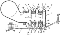
фиг.2 - распределитель на разветвлении трубки;figure 2 - distributor at the branching of the tube;
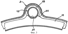
фиг.3 - способ крепления узла на кольце;figure 3 - method of mounting the node on the ring;
фиг.4 - группу коллекторов в разрезе вблизи их концевых частей и крепежного средства коллекторов на кольце;4 is a group of collectors in the context near their end parts and mounting means of the collectors on the ring;
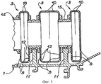
фиг.5 - вариант выполнения распределителя.5 is an embodiment of a dispenser.
Как показано на фиг.1, статорное кольцо 1 соединено с группой вентиляционных узлов 2 согласно изобретению, каждый из которых занимает часть периметра кольца 1 и содержит группу параллельных коллекторов 3, выполненных в виде дуги окружности, распределитель 4, который распределяет вентиляционный воздух между всеми коллекторами 3, и подводящую трубку 5 (показана на фиг.2), соединенную с распределителем 4. Обычно подводящие трубки 5 соединяются вместе через один или несколько распределителей, хотя эти распределители не показаны, поскольку они не являются предметом данного изобретения, которое относится более точно к концевым частям вентиляционных узлов 2, другими словами, к их частям, которые находятся вблизи кольца, подлежащего вентиляции. Следует обратить внимание также на крепежные средства коллекторов 3 на кольце 1, включая планки 6, концы которых прикреплены к кольцу 1, при этом каждая планка накрывает конец каждой группы коллекторов 3, проходя над ними.As shown in figure 1, the stator ring 1 is connected to a group of
Как показано также на фиг.2, каждый из коллекторов 3 содержит левую полуоболочку 7 и правую полуоболочку 8. Более точно, каждая из полуоболочек 7 и 8 этих двух типов содержит торцевую часть 9, которая приблизительно плоская, и обод 10, образованный вокруг торцевой части 9, при этом обода 10 взаимодополняющих пар полуоболочек 7 и 8 расположены вдоль одной линии и соединены с образованием одного коллектора. Полуоболочки 7 и 8 можно изготавливать с помощью простой операции штамповки, а соединения между ободами 10 можно выполнять с помощью сварки. Этот способ изготовления является чрезвычайно простым и не требует машинной обработки труб для придания им требуемых форм и размеров, что было бы намного более сложнее. Кроме того, все левые полуоболочки 7 можно обычно изготавливать с использованием того же инструмента, что и для правых полуоболочек 8, которые являются симметричными левым полуоболочкам относительно плоскости соединения. Эта общая аналогичность не означает, что отсутствуют некоторые различия в деталях. Например, полуоболочки 7 и 8 могут быть изготовлены с различной шириной ободов 10, например, для обеспечения преимущества вентиляции через наиболее широкие коллекторы 3. Пример использования этого процесса показан на фиг.5, где три коллектора 3 вентилируют два ребра 11, при этом центральный коллектор расположен между двумя ребрами 11 и вентилирует оба ребра, что оправдывает удвоение его ширины. Продувочные отверстия 12, через которые воздух выходит из коллекторов 3, выполняют до или после штамповки полуоболочек 7 и 8, при этом отверстия не выполняют в концевых полуоболочках, перед которыми нет ребер 11.As also shown in FIG. 2, each of the collectors 3 comprises a left half-
Как показано на фиг.2, другие более широкие отверстия, обозначенные позицией 13, выполнены через боковые части 14 торцевых частей 9, кроме одной оконечной торцевой части 9, для образования распределителя 4. Боковые части 14 проходят в этом варианте выполнения в боковом направлении от центров торцевых частей 9 и находятся с ними в одной плоскости. Концы коллекторов 3 закрыты сплошными пластинами, приваренными к ним.As shown in FIG. 2, other wider openings, indicated by 13, are made through the side parts 14 of the
Распределитель 4 содержит также втулки 15 в виде коротких цилиндров, выполняющих роль распорок между коллекторами 3 и подводящей трубкой 5. Часто является предпочтительным, чтобы они были аналогичными, однако они могут отличаться, в частности, по длине. Втулки содержат концевые части 16, выполненные в виде выступов, которые входят в отверстия 13 в коллекторах 3 для удерживания их на месте, и буртики 17, опирающиеся на коллекторы 3, что обеспечивает раздельное расположение коллекторов. При окончательной сборке распределителя 4 втулки 15 приваривают к коллекторам 3. Однако подводящая трубка 5 обычно отделена от распределителя 4 и может скользить во входной втулке 15, при этом между ними установлено уплотнение 18.The distributor 4 also contains
Одна из втулок содержит плоские поверхности 19, параллельные коллекторам, опирающиеся на ребро 11 статорного кольца 1. Для окончания описания фиг.2 следует отметить, что одна из втулок 15 содержит плоские и расположенные напротив друг друга поверхности 19, охватывающие конец 20 (в данном случае он показан увеличенным) ребра 11, при этом соответствующая втулка 15 находится сверху ребра 11. Уменьшение осевого зазора между втулкой 15 и расширенной частью ребра 11 способствует осевому позиционированию распределителя 4 на кольце 1. Это означает, что осевое положение распределителя 4 задано, и воздушные зазоры между коллекторами 3 и ребрами 11 можно регулировать более точно и тем самым лучше управлять конвекционным обменом с помощью воздуха, продуваемого над ребрами 11. Следует отметить, что вторая втулка перекрывает соответствующее ей ребро с осевым зазором для обеспечения относительного расширения между распределителями 4 и кольцом 1 без возникновения гиперстатических соединений и нежелательных связей.One of the bushings contains
Конструкция вентиляционного узла, изготавливаемого из стандартных элементов, сваренных друг с другом, является особенно простой и предпочтительной. Ниже приводится описание крепления вентиляционного узла 2 к кольцу 1. Как показано на фиг.3, конец 20 ребра 11 снабжен V-образной канавкой, на которую опирается центральная цилиндрическая часть втулки 15 с самоцентрированием для защиты распределителя 4 от радиальных и тангенциальных перемещений кольца 1; это обеспечивает точное радиальное и тангенциальное позиционирование распределителя и его ориентацию вдоль центральной оси двигателя.The design of the ventilation unit made of standard elements welded together is particularly simple and preferred. Below is a description of the attachment of the
Ниже приводится описание планок 6 со ссылками на фиг.4, на которой показано как они обеспечивают взаимно дополняющую опору коллекторов 3. Скобы 22 прикреплены к одному концу статорного кольца 1 с помощью крепежных болтов 23 и содержат фланец 24, находящийся под одним концом планки 6; другой конец планки расположен на бобышке 25 статорного кольца 1. Крепежные средства 26 и 27, выполненные в виде болтов, прикручены к фланцу 24 и бобышке 25. Они удерживают концы планки 6 на фланце и на бобышке, сжимая пружины 28, опирающиеся на планку 6 через шайбы 29. Такой тип сборки обеспечивает лучшее управление нажимом планок 6 на скобы 24 и бобышки 25. Если эта сила слишком велика, то узел является жестким и не допускает перемещений, вызванных температурой. Лучшее управление обуславливается тем фактом, что проще устанавливать силу сжатия пружины 28 посредством регулирования высоты под буртиком стакана 31, чем регулировать силу натяжения крепежного средства 26, выполненного в виде болта, посредством его затягивания с заданным моментом. Кроме того, планка 6, к которой приварены коллекторы 3, выполнена с широкими отверстиями 30 вокруг крепежных средств 26 и 27, выполненных в виде болтов, так что она может скользить в осевом направлении и тангенциально относительно статорного кольца. Поэтому такая гибкая сборка предотвращает образование слишком больших внутренних напряжений в вентиляционном узле 2, поскольку коллекторы 3 могут перемещаться над кольцом 1 без приложения слишком больших сил. Эти относительные перемещения обычно обуславливаются различным тепловым расширением. Давление одной из втулок 15 на конец 20 соответствующего ребра 11 также придает некоторую гибкость за счет обеспечения возможности перемещения вентиляционного узла 2 на его концах, в то время как он притягивается в направлении статорного кольца 1 и дна V-образной канавки 21 пружинами 28. Эта гибкость имеет важное значение, поскольку она допускает неизбежные различные тепловые расширения, которые возникают в оборудовании этого типа.Below is a description of the strips 6 with reference to figure 4, which shows how they provide a mutually complementary support for the manifolds 3. The
Claims (7)
Applications Claiming Priority (2)
| Application Number | Priority Date | Filing Date | Title |
|---|---|---|---|
| FR0014373A FR2816352B1 (en) | 2000-11-09 | 2000-11-09 | VENTILATION ASSEMBLY OF A STATOR RING |
| FR0014373 | 2000-11-09 |
Publications (2)
| Publication Number | Publication Date |
|---|---|
| RU2001130175A RU2001130175A (en) | 2003-07-10 |
| RU2276733C2 true RU2276733C2 (en) | 2006-05-20 |
Family
ID=8856230
Family Applications (1)
| Application Number | Title | Priority Date | Filing Date |
|---|---|---|---|
| RU2001130175/06A RU2276733C2 (en) | 2000-11-09 | 2001-11-08 | Stator ring ventilating unit |
Country Status (9)
| Country | Link |
|---|---|
| US (1) | US6896038B2 (en) |
| EP (1) | EP1205637B1 (en) |
| JP (1) | JP3913032B2 (en) |
| CA (1) | CA2361103C (en) |
| DE (1) | DE60100448T2 (en) |
| ES (1) | ES2199921T3 (en) |
| FR (1) | FR2816352B1 (en) |
| RU (1) | RU2276733C2 (en) |
| UA (1) | UA73938C2 (en) |
Cited By (3)
| Publication number | Priority date | Publication date | Assignee | Title |
|---|---|---|---|---|
| RU2503822C2 (en) * | 2008-05-28 | 2014-01-10 | Снекма | High pressure turbine with improved chamber of radial gap control of moving blades, and turbo-machine using such turbine |
| RU2567892C1 (en) * | 2014-06-02 | 2015-11-10 | Российская Федерация, от имени которой выступает Министерство промышленности и торговли Российской Федерации (Минпромторг России) | High-pressure compressor stator |
| RU2567885C1 (en) * | 2014-08-08 | 2015-11-10 | Российская Федерация, от имени которой выступает Министерство промышленности и торговли Российской Федерации (Минпромторг России) | Compressor stator |
Families Citing this family (37)
| Publication number | Priority date | Publication date | Assignee | Title |
|---|---|---|---|---|
| FR2829525B1 (en) * | 2001-09-13 | 2004-03-12 | Snecma Moteurs | ASSEMBLY OF SECTORS OF A TURBINE DISTRIBUTOR TO A CRANKCASE |
| FR2865237B1 (en) * | 2004-01-16 | 2006-03-10 | Snecma Moteurs | IMPROVEMENTS IN GAME CONTROL DEVICES IN A GAS TURBINE |
| FR2867806B1 (en) * | 2004-03-18 | 2006-06-02 | Snecma Moteurs | DEVICE FOR CONTROLLING GAS TURBINE SET WITH AIR FLOW BALANCING |
| FR2867805A1 (en) * | 2004-03-18 | 2005-09-23 | Snecma Moteurs | TURBOMACHINE HIGH-PRESSURE TURBINE STATOR AND METHOD OF ASSEMBLY |
| US7597537B2 (en) * | 2005-12-16 | 2009-10-06 | General Electric Company | Thermal control of gas turbine engine rings for active clearance control |
| US7503179B2 (en) * | 2005-12-16 | 2009-03-17 | General Electric Company | System and method to exhaust spent cooling air of gas turbine engine active clearance control |
| US7785063B2 (en) * | 2006-12-15 | 2010-08-31 | Siemens Energy, Inc. | Tip clearance control |
| US7914254B2 (en) * | 2007-02-13 | 2011-03-29 | General Electric Company | Integrated support/thermocouple housing for impingement cooling manifolds and cooling method |
| GB0906059D0 (en) * | 2009-04-08 | 2009-05-20 | Rolls Royce Plc | Thermal control system for turbines |
| GB2469490B (en) * | 2009-04-16 | 2012-03-07 | Rolls Royce Plc | Turbine casing cooling |
| GB201013723D0 (en) | 2010-08-17 | 2010-09-29 | Rolls Royce Plc | Manifold mounting arrangement |
| FR2977276B1 (en) * | 2011-06-30 | 2016-12-09 | Snecma | ARRANGEMENT FOR CONNECTING A DUCT TO AN AIR DISTRIBUTION HOUSING |
| ITTO20120519A1 (en) | 2012-06-14 | 2013-12-15 | Avio Spa | GAS TURBINE FOR AERONAUTICAL MOTORS |
| US9341074B2 (en) * | 2012-07-25 | 2016-05-17 | General Electric Company | Active clearance control manifold system |
| FR2999642B1 (en) * | 2012-12-17 | 2018-09-28 | Safran Aircraft Engines | STATORIC ASSEMBLY HAVING DAMAGE WITH HOLLOW OR HIGH PORTIONS |
| EP3105439B1 (en) * | 2014-02-04 | 2019-12-11 | United Technologies Corporation | Clearance control system with brackets |
| US9869196B2 (en) * | 2014-06-24 | 2018-01-16 | General Electric Company | Gas turbine engine spring mounted manifold |
| FR3040429B1 (en) * | 2015-08-27 | 2019-06-07 | Safran Aircraft Engines | DEVICE FOR FASTENING AIR COOLED COOLING RAMPS OF A TURBOMACHINE TURBINE |
| FR3040428B1 (en) * | 2015-08-27 | 2017-09-01 | Snecma | DEVICE FOR COOLING AIR JETS OF THE CARTER OF A TURBINE OF A TURBOMACHINE |
| US10513944B2 (en) * | 2015-12-21 | 2019-12-24 | General Electric Company | Manifold for use in a clearance control system and method of manufacturing |
| US10329941B2 (en) * | 2016-05-06 | 2019-06-25 | United Technologies Corporation | Impingement manifold |
| CN107795383B (en) * | 2016-08-29 | 2019-08-06 | 中国航发商用航空发动机有限责任公司 | A kind of gas turbine cooling air distribution system |
| FR3058459B1 (en) * | 2016-11-04 | 2018-11-09 | Safran Aircraft Engines | COOLING DEVICE FOR TURBINE OF A TURBOMACHINE |
| FR3058460B1 (en) | 2016-11-08 | 2018-11-09 | Safran Aircraft Engines | CONNECTION ASSEMBLY FOR COOLING TURBOMACHINE TURBINE |
| CN106382136B (en) * | 2016-11-18 | 2017-07-25 | 中国科学院工程热物理研究所 | A kind of transonic speed tip active control device |
| US10458281B2 (en) * | 2017-06-12 | 2019-10-29 | United Technologies Corporation | Resilient mounting assembly for a turbine engine |
| FR3073007B1 (en) * | 2017-10-27 | 2019-09-27 | Safran Aircraft Engines | DEVICE FOR HOLDING A COOLING TUBE FOR A TURBOMACHINE HOUSING |
| FR3079874B1 (en) * | 2018-04-09 | 2020-03-13 | Safran Aircraft Engines | COOLING DEVICE FOR A TURBINE OF A TURBOMACHINE |
| FR3081927B1 (en) * | 2018-05-30 | 2020-11-20 | Safran Aircraft Engines | TURBOMACHINE CASING COOLING SYSTEM |
| FR3082872B1 (en) * | 2018-06-25 | 2021-06-04 | Safran Aircraft Engines | TURBOMACHINE CASE COOLING SYSTEM |
| FR3089560B1 (en) * | 2018-12-06 | 2021-01-22 | Safran Aircraft Engines | Device for maintaining a cooling tube for a turbomachine casing |
| FR3089545B1 (en) * | 2018-12-07 | 2021-01-29 | Safran Aircraft Engines | Device for cooling a turbine housing for a turbomachine |
| FR3089544B1 (en) * | 2018-12-10 | 2021-02-19 | Safran Aircraft Engines | TURBOMACHINE CASE COOLING DEVICE |
| FR3099801B1 (en) * | 2019-08-09 | 2021-12-03 | Safran Aircraft Engines | Set for a turbomachine turbine |
| FR3099798B1 (en) * | 2019-08-09 | 2021-12-03 | Safran Aircraft Engines | Set for a turbomachine turbine |
| FR3109406B1 (en) * | 2020-04-17 | 2022-10-07 | Safran Aircraft Engines | TURBINE CASE COOLING DEVICE |
| US11788425B2 (en) * | 2021-11-05 | 2023-10-17 | General Electric Company | Gas turbine engine with clearance control system |
Family Cites Families (20)
| Publication number | Priority date | Publication date | Assignee | Title |
|---|---|---|---|---|
| DE1601187A1 (en) * | 1967-07-15 | 1972-01-27 | Eberspaecher J | Heat exchanger, preferably with an internal boiler room, especially for motor vehicles |
| US3756020A (en) * | 1972-06-26 | 1973-09-04 | Curtiss Wright Corp | Gas turbine engine and cooling system therefor |
| US3818696A (en) * | 1972-10-25 | 1974-06-25 | A Beaufrere | Regenerative air-cooled gas turbine engine |
| DE2855055C2 (en) * | 1978-12-20 | 1982-12-16 | Siemens AG, 1000 Berlin und 8000 München | Insulating sleeve for a laminated core to be wound with a ring winding |
| US4279123A (en) * | 1978-12-20 | 1981-07-21 | United Technologies Corporation | External gas turbine engine cooling for clearance control |
| US4773981A (en) * | 1982-07-29 | 1988-09-27 | Stephen Masiuk | Apparatus for improving internal combustion engine efficiency |
| US4828403A (en) * | 1987-04-03 | 1989-05-09 | Schwartzman Everett H | Resiliently mounted fluid bearing assembly |
| JPH06575Y2 (en) * | 1988-06-16 | 1994-01-05 | 川崎重工業株式会社 | Muffler for internal combustion engine |
| US5100291A (en) * | 1990-03-28 | 1992-03-31 | General Electric Company | Impingement manifold |
| US5205115A (en) * | 1991-11-04 | 1993-04-27 | General Electric Company | Gas turbine engine case counterflow thermal control |
| US5273396A (en) * | 1992-06-22 | 1993-12-28 | General Electric Company | Arrangement for defining improved cooling airflow supply path through clearance control ring and shroud |
| US5399066A (en) * | 1993-09-30 | 1995-03-21 | General Electric Company | Integral clearance control impingement manifold and environmental shield |
| FR2750451B1 (en) * | 1996-06-27 | 1998-08-07 | Snecma | DEVICE FOR BLOWING GAS ADJUSTING GAMES IN A TURBOMACHINE |
| FR2766517B1 (en) * | 1997-07-24 | 1999-09-03 | Snecma | DEVICE FOR VENTILATION OF A TURBOMACHINE RING |
| FR2800797B1 (en) * | 1999-11-10 | 2001-12-07 | Snecma | ASSEMBLY OF A RING BORDING A TURBINE TO THE TURBINE STRUCTURE |
| FR2803871B1 (en) * | 2000-01-13 | 2002-06-07 | Snecma Moteurs | DIAMETER ADJUSTMENT ARRANGEMENT OF A GAS TURBINE STATOR |
| DE10026355B4 (en) * | 2000-05-27 | 2010-06-17 | Mahle Filtersysteme Gmbh | Sound-absorbing air duct |
| FR2817290B1 (en) * | 2000-11-30 | 2003-02-21 | Snecma Moteurs | ROTOR BLADE DISC FLANGE AND CORRESPONDING ARRANGEMENT |
| FR2819010B1 (en) * | 2001-01-04 | 2004-05-28 | Snecma Moteurs | STATOR RING SUPPORT AREA OF THE TURBINE HIGH PRESSURE TURBINE ROTATOR WITH A TURBOMACHINE |
| FR2831918B1 (en) * | 2001-11-08 | 2004-05-28 | Snecma Moteurs | STATOR FOR TURBOMACHINE |
-
2000
- 2000-11-09 FR FR0014373A patent/FR2816352B1/en not_active Expired - Fee Related
-
2001
- 2001-10-26 JP JP2001328678A patent/JP3913032B2/en not_active Expired - Fee Related
- 2001-11-06 CA CA002361103A patent/CA2361103C/en not_active Expired - Fee Related
- 2001-11-08 EP EP01402865A patent/EP1205637B1/en not_active Expired - Lifetime
- 2001-11-08 RU RU2001130175/06A patent/RU2276733C2/en not_active IP Right Cessation
- 2001-11-08 US US09/986,280 patent/US6896038B2/en not_active Expired - Lifetime
- 2001-11-08 ES ES01402865T patent/ES2199921T3/en not_active Expired - Lifetime
- 2001-11-08 DE DE60100448T patent/DE60100448T2/en not_active Expired - Lifetime
- 2001-11-08 UA UA2001117658A patent/UA73938C2/en unknown
Cited By (3)
| Publication number | Priority date | Publication date | Assignee | Title |
|---|---|---|---|---|
| RU2503822C2 (en) * | 2008-05-28 | 2014-01-10 | Снекма | High pressure turbine with improved chamber of radial gap control of moving blades, and turbo-machine using such turbine |
| RU2567892C1 (en) * | 2014-06-02 | 2015-11-10 | Российская Федерация, от имени которой выступает Министерство промышленности и торговли Российской Федерации (Минпромторг России) | High-pressure compressor stator |
| RU2567885C1 (en) * | 2014-08-08 | 2015-11-10 | Российская Федерация, от имени которой выступает Министерство промышленности и торговли Российской Федерации (Минпромторг России) | Compressor stator |
Also Published As
| Publication number | Publication date |
|---|---|
| FR2816352B1 (en) | 2003-01-31 |
| UA73938C2 (en) | 2005-10-17 |
| DE60100448D1 (en) | 2003-08-14 |
| CA2361103A1 (en) | 2002-05-09 |
| CA2361103C (en) | 2009-12-29 |
| JP3913032B2 (en) | 2007-05-09 |
| EP1205637A1 (en) | 2002-05-15 |
| FR2816352A1 (en) | 2002-05-10 |
| US6896038B2 (en) | 2005-05-24 |
| ES2199921T3 (en) | 2004-03-01 |
| EP1205637B1 (en) | 2003-07-09 |
| DE60100448T2 (en) | 2004-04-15 |
| JP2002195007A (en) | 2002-07-10 |
| US20020053837A1 (en) | 2002-05-09 |
Similar Documents
| Publication | Publication Date | Title |
|---|---|---|
| RU2276733C2 (en) | Stator ring ventilating unit | |
| RU2347079C2 (en) | Turbomachine with cooled annular segments | |
| US9869196B2 (en) | Gas turbine engine spring mounted manifold | |
| JP4582471B2 (en) | Turbine frame assembly | |
| US8070445B2 (en) | Balancing system for turbomachine rotor | |
| CA2715227C (en) | Sealing for vane segments | |
| JP2581742B2 (en) | Frame assembly for gas turbine engine | |
| JP4230996B2 (en) | Heat-free rear frame for transition ducts | |
| RU2001130175A (en) | Stator ring ventilation assembly | |
| US11371387B2 (en) | Cooling device for a turbine of a turbomachine | |
| EP1096207B1 (en) | Combustor mounting for a gas turbine engine | |
| CN111902607B (en) | Cooling apparatus for a turbine of a turbine engine | |
| US11274568B2 (en) | Cooling device for a turbine of a turbomachine | |
| US8668438B2 (en) | Turbine casing cooling | |
| JP2006097680A (en) | Turbo fan jet engine having accessory part connection part arm and accessory part connection part arm | |
| JP2004044583A (en) | Gas turbine | |
| JP7219763B2 (en) | Cooling tube holding device for turbomachine casing | |
| US4696619A (en) | Housing for a turbojet engine compressor | |
| US11555405B2 (en) | Device for holding a cooling tube for a turbomachine casing | |
| US6733231B2 (en) | Vapor tube structure of gas turbine | |
| JP2606996B2 (en) | Centrifugal compressor and method of incorporating silencer therewith | |
| KR100218603B1 (en) | Supporting arrangement of steam turbine | |
| JP3593481B2 (en) | Heat insulation plate mounting device | |
| JPH0366484B2 (en) | ||
| JPH01134025A (en) | Housing structure for turbo-charger |
Legal Events
| Date | Code | Title | Description |
|---|---|---|---|
| MM4A | The patent is invalid due to non-payment of fees |
Effective date: 20171109 |