RU2275508C2 - Cooled blade of rotor for industrial gas-turbine plant (versions) - Google Patents
Cooled blade of rotor for industrial gas-turbine plant (versions) Download PDFInfo
- Publication number
- RU2275508C2 RU2275508C2 RU2002132867/06A RU2002132867A RU2275508C2 RU 2275508 C2 RU2275508 C2 RU 2275508C2 RU 2002132867/06 A RU2002132867/06 A RU 2002132867/06A RU 2002132867 A RU2002132867 A RU 2002132867A RU 2275508 C2 RU2275508 C2 RU 2275508C2
- Authority
- RU
- Russia
- Prior art keywords
- channel
- protrusions
- pen
- protrusion
- segment
- Prior art date
Links
Images
Classifications
-
- F—MECHANICAL ENGINEERING; LIGHTING; HEATING; WEAPONS; BLASTING
- F01—MACHINES OR ENGINES IN GENERAL; ENGINE PLANTS IN GENERAL; STEAM ENGINES
- F01D—NON-POSITIVE DISPLACEMENT MACHINES OR ENGINES, e.g. STEAM TURBINES
- F01D5/00—Blades; Blade-carrying members; Heating, heat-insulating, cooling or antivibration means on the blades or the members
- F01D5/12—Blades
- F01D5/14—Form or construction
- F01D5/18—Hollow blades, i.e. blades with cooling or heating channels or cavities; Heating, heat-insulating or cooling means on blades
- F01D5/187—Convection cooling
-
- F—MECHANICAL ENGINEERING; LIGHTING; HEATING; WEAPONS; BLASTING
- F05—INDEXING SCHEMES RELATING TO ENGINES OR PUMPS IN VARIOUS SUBCLASSES OF CLASSES F01-F04
- F05D—INDEXING SCHEME FOR ASPECTS RELATING TO NON-POSITIVE-DISPLACEMENT MACHINES OR ENGINES, GAS-TURBINES OR JET-PROPULSION PLANTS
- F05D2260/00—Function
- F05D2260/20—Heat transfer, e.g. cooling
- F05D2260/221—Improvement of heat transfer
- F05D2260/2214—Improvement of heat transfer by increasing the heat transfer surface
- F05D2260/22141—Improvement of heat transfer by increasing the heat transfer surface using fins or ribs
-
- Y—GENERAL TAGGING OF NEW TECHNOLOGICAL DEVELOPMENTS; GENERAL TAGGING OF CROSS-SECTIONAL TECHNOLOGIES SPANNING OVER SEVERAL SECTIONS OF THE IPC; TECHNICAL SUBJECTS COVERED BY FORMER USPC CROSS-REFERENCE ART COLLECTIONS [XRACs] AND DIGESTS
- Y02—TECHNOLOGIES OR APPLICATIONS FOR MITIGATION OR ADAPTATION AGAINST CLIMATE CHANGE
- Y02T—CLIMATE CHANGE MITIGATION TECHNOLOGIES RELATED TO TRANSPORTATION
- Y02T50/00—Aeronautics or air transport
- Y02T50/60—Efficient propulsion technologies, e.g. for aircraft
Abstract
Description
Область техники, к которой относится изобретениеFIELD OF THE INVENTION
Настоящее изобретение относится к охлаждаемым компонентам аэродинамического профиля типа применяемых в промышленных газотурбинных установках и, более конкретно, к структуре, обеспечивающей подачу текучей среды, такой как воздух, к критическим зонам аэродинамического профиля.The present invention relates to cooled components of the aerodynamic profile of the type used in industrial gas turbine plants and, more specifically, to a structure that provides a fluid medium, such as air, to the critical zones of the aerodynamic profile.
Уровень техникиState of the art
Газотурбинные установки для воздушных судов используют лопатки ротора (называемые также рабочими лопатками), которые в типичном случае подвергаются охлаждению с целью уменьшения температурных напряжений. Уменьшение напряжений обеспечивает достаточную структурную прочность и долговечность турбинных лопаток. Были разработаны очень сложные схемы внутреннего охлаждения лопатки с использованием каналов для протекания текучей среды, в частности воздуха, имеющих извилистую (петлевую) форму.Gas turbine units for aircraft use rotor blades (also called rotor blades), which are typically cooled to reduce temperature stresses. The stress reduction provides sufficient structural strength and durability of the turbine blades. Very complex schemes for the internal cooling of the blade using channels for the flow of a fluid, in particular air, having a meandering (loop) shape have been developed.
В подобных применениях типичным является также использование теплопроводящих элементов, таких как ленточные, или полосковые выступы, служащих для создания турбулентного потока. Конструкции таких выступов (описанные, например, в патентах США №5695321, F 01 D 005/18, 09.12.1997 и 5738493, F 04 D 029/58, 14.04.1998) становятся все более сложными, в частности, предусматривающими вариации выступов по высоте, длине и углу наклона по отношению к направлению потока текучей среды в соответствующем канале. Эти конструкции определяются, в основном, учетом микроскопических факторов усиления теплопередачи в очень малой зоне пера лопатки, хотя и относятся к перу лопатки в целом.In such applications, it is also typical to use heat-conducting elements, such as tape or strip protrusions, which serve to create a turbulent flow. The designs of such protrusions (described, for example, in US Pat. Nos. 5,695,321, F 01 D 005/18, 12/09/1997, and 5,738,493, F 04 D 029/58, 04/14/1998) are becoming more complex, in particular, involving variations of the protrusions according to height, length and angle of inclination with respect to the direction of fluid flow in the corresponding channel. These designs are determined mainly by taking into account the microscopic factors of heat transfer enhancement in a very small area of the blade feather, although they relate to the blade feather as a whole.
Подобные теплопроводящие элементы увеличивают способность структуры пера лопатки передавать тепло охлаждающей текучей среды при ее движении внутри пера. Одним из показателей качества подобных конструкций является эффективность теплопередачи структуры, определяемая как мера способности части канала передавать тепло при наличии заданной разности температур от стенки, ограничивающей отрезок канала, к охлаждающей текучей среде, протекающей по данному отрезку с определенной скоростью и при определенной температуре. Эффективность теплопередачи при неизменных прочих параметрах повышается при увеличении высоты выступа или уменьшении угла разворота между выступами при увеличении падения давления, под действием которого создается поток, во время протекания мимо выступов. Для сравнения получаемых результатов удобно использовать параметр, представляющий собой нормализованное отношение высоты выступов к углу их взаимного разворота, т.е. значение высоты выступа, деленное на угол разворота и умноженное на 100.Such heat-conducting elements increase the ability of the structure of the blade pen to transfer heat from the cooling fluid as it moves inside the pen. One of the quality indicators of such structures is the heat transfer efficiency of the structure, defined as a measure of the ability of a part of the channel to transfer heat in the presence of a given temperature difference from the wall that bounds the channel section to the cooling fluid flowing along this segment at a certain speed and at a certain temperature. The heat transfer efficiency, with other parameters unchanged, increases with an increase in the height of the protrusion or a decrease in the angle of rotation between the protrusions with an increase in the pressure drop, under the influence of which a flow is created, while flowing past the protrusions. To compare the results obtained, it is convenient to use a parameter representing the normalized ratio of the height of the protrusions to the angle of their mutual reversal, i.e. the value of the height of the ledge divided by the angle of rotation and multiplied by 100.
После определения названных конкретных параметров для малых зон пера лопатки необходимо еще решить проблему их использования таким образом, чтобы усилить теплопередачу, но не допустить неприемлемого возрастания стоимости изготовления.After determining the specified specific parameters for small areas of the feather blade, it is still necessary to solve the problem of their use in such a way as to enhance heat transfer, but to prevent an unacceptable increase in manufacturing cost.
Одну из важных областей для задач подобного рода представляют собой лопатки для промышленных газотурбинных установок. Наиболее близким аналогом предложенных технических решений является охлаждаемая лопатка ротора для промышленной газотурбинной установки, описанная в документе US 5395212 А, F 01 D 005/18, 07.03.1995. Известная лопатка имеет передний контур для охлаждающего воздуха и задний контур для охлаждающего воздуха. При этом перо лопатки имеет входную и выходную кромки, а также боковые стенки, образующие спинку и корыто пера. Между корытом и спинкой пера образована полость, через которую проходят контуры для охлаждающего воздуха и в которой расположены первый, передний петлевой канал и второй, задний петлевой канал. Известная лопатка ротора содержит также наборы ленточных выступов в каждом из петлевых каналов. При этом ленточные выступы каждого набора взаимно смещены в продольном направлении с заданным шагом, а также пространственно отделены от смежных ленточных выступов того же набора на другой стенке.One of the important areas for tasks of this kind are blades for industrial gas turbine plants. The closest analogue of the proposed technical solutions is a cooled rotor blade for an industrial gas turbine installation, described in the document US 5395212 A, F 01 D 005/18, 03.03.1995. The known blade has a front circuit for cooling air and a rear circuit for cooling air. In this case, the feather of the blade has an input and output edges, as well as side walls forming the back and trough of the feather. A cavity is formed between the trough and the back of the pen through which the cooling air circuits pass and in which the first, front loop channel and the second, rear loop channel are located. The known rotor blade also contains sets of tape protrusions in each of the loop channels. In this case, the tape protrusions of each set are mutually offset in the longitudinal direction with a given step, as well as spatially separated from adjacent tape protrusions of the same set on another wall.
Поскольку в данной лопатке отношение высоты выступов к их шагу не оптимизировано по длине каждого петлевого канала, известное техническое решение характеризуется ограниченной эффективностью теплопередачи и, как следствие, ограниченной эффективностью охлаждающего контура в целом.Since in this blade the ratio of the height of the protrusions to their pitch is not optimized along the length of each loop channel, the known technical solution is characterized by limited heat transfer efficiency and, as a result, limited efficiency of the cooling circuit as a whole.
Раскрытие изобретенияDisclosure of invention
В связи с изложенным задача, на решение которой были направлены усилия изобретателей, заключается в разработке таких схем охлаждения пера лопатки в промышленных газотурбинных установках, которые обеспечивают приемлемую эффективность теплопередачи и приемлемую стоимость.In connection with the stated problem, the efforts of the inventors were aimed at solving it, is to develop such schemes for cooling the blade feathers in industrial gas turbine plants, which provide an acceptable heat transfer efficiency and an acceptable cost.
Настоящее изобретение частично основано на осознании того, что лопатка ротора в промышленной газотурбинной установке подвергается максимальной тепловой нагрузке при работе в стационарных условиях. При этом в ней существуют зоны локализации максимальной тепловой нагрузки, положение которых на пере лопатки остается относительно постоянным в течение длительных периодов. Положение этих зон не изменяется даже в случае изменений температуры потока текучей среды по длине канала, которые могут иметь место в случае использования камер сгорания трубчатого или трубчато-кольцевого типов. Таким образом, по сравнению с лопатками газотурбинных установок воздушных судов, положение высокотемпературных зон на лопатках промышленных установок можно считать постоянным во времени. Применительно к газотурбинным установкам воздушных судов максимальные тепловые нагрузки в типичном случае имеют место во время переходных периодов при взлете, т.е. на минимальной высоте, со снижением нагрузок при работе в стабильном крейсерском режиме. В этих условиях размеры и положение зон максимальной тепловой нагрузки смещаются по перу лопатки в связи с изменением характеристик охлаждающего потока воздуха при изменении режима полета, а также в связи с изменением тепловой нагрузки на канал охлаждения пера в результате изменения температуры и скорости газа в указанном канале.The present invention is partially based on the realization that the rotor blade in an industrial gas turbine installation is subjected to maximum thermal load when operating in stationary conditions. Moreover, there are zones of localization of the maximum heat load in it, the position of which on the shoulder blades remains relatively constant for long periods. The position of these zones does not change even in the case of changes in the temperature of the fluid flow along the length of the channel, which may occur in the case of using combustion chambers of a tubular or tubular-annular type. Thus, in comparison with the blades of gas turbine units of aircraft, the position of the high-temperature zones on the blades of industrial plants can be considered constant in time. As applied to aircraft gas turbine installations, the maximum heat loads typically occur during transition periods during take-off, i.e. at a minimum height, with reduced loads when operating in stable cruising mode. Under these conditions, the size and position of the zones of maximum thermal load are shifted along the feather of the blade due to a change in the characteristics of the cooling air flow when the flight mode changes, and also due to a change in the thermal load on the feather cooling channel as a result of changes in temperature and gas velocity in the specified channel.
Названное обстоятельство позволяет более тщательно оптимизировать конструкцию внутренних охлаждающих каналов в промышленной газотурбинной установке и сообщает некоторую гибкость в выборе конструкции, т.е. дает возможность разработать лопатку с пером, более простым в изготовлении, чем у лопаток, применяемых на авиационных газотурбинных установках. Такое упрощение может быть достигнуто в лопатках для промышленных газотурбинных установок за счет сокращения вариаций, в частности в конструкции наборов ленточных выступов по сравнению с аэродинамическим профилем (пером) лопатки авиационного двигателя, где необходимо учитывать смещение положения зоны максимальной теплопередачи при переходе на другой рабочий режим.The aforementioned circumstance makes it possible to more thoroughly optimize the design of internal cooling channels in an industrial gas turbine installation and provides some flexibility in the choice of design, i.e. makes it possible to develop a blade with a feather that is easier to manufacture than blades used in aircraft gas turbine installations. This simplification can be achieved in the blades for industrial gas turbine plants due to the reduction of variations, in particular, in the design of sets of tape protrusions in comparison with the aerodynamic profile (feather) of an aircraft engine blade, where it is necessary to take into account the shift in the position of the zone of maximum heat transfer when switching to another operating mode.
Кроме того, настоящее изобретение частично основывается на осознании того, что применительно к перу лопатки для промышленной газотурбинной установки, имеющему два петлевых канала, каждый из которых включает в себя три последовательно соединенных отрезка для протекания по ним охлаждающего воздуха от средней части пера к областям вблизи кромок пера, максимальная тепловая нагрузка имеет место в областях входной и выходной кромок. Охлаждающий воздух течет к третьему отрезку каждого петлевого канала, ближайшему по отношению к области соответствующей кромки, и выводится из петлевого канала через этот третий отрезок. Дополнительно в этой известной конфигурации предусматривается канал для охлаждающего воздуха в области входной кромки, т.е. лежащий между петлевым каналом и входной кромкой.In addition, the present invention is based in part on the realization that, with respect to a pen, blades for an industrial gas turbine installation having two loop channels, each of which includes three segments connected in series for cooling air to flow from the middle part of the pen to areas near the edges pen, the maximum thermal load occurs in the areas of the input and output edges. Cooling air flows to the third segment of each loop channel closest to the region of the corresponding edge and is discharged from the loop channel through this third segment. Additionally, in this known configuration, a channel for cooling air is provided in the region of the inlet edge, i.e. lying between the loop channel and the input edge.
В соответствии с настоящим изобретением охлаждаемая рабочая лопатка (лопатка ротора) для промышленной газотурбинной установки согласно первому основному варианту выполнения имеет передний контур для охлаждающего воздуха и задний контур для охлаждающего воздуха. При этом перо лопатки по изобретению имеет область входной кромки, область выходной кромки и среднюю область, расположенную между областями входной и выходной кромок, а также боковые стенки, образующие спинку и корыто пера и соединяющиеся в области передней кромки и в области задней кромки с образованием полости между ними. Через данную полость проходят, по меньшей мере, частично контуры для охлаждающего воздуха, причем в ней расположены первый, передний петлевой канал и второй, задний петлевой канал.In accordance with the present invention, a cooled working blade (rotor blade) for an industrial gas turbine installation according to the first main embodiment has a front circuit for cooling air and a rear circuit for cooling air. In this case, the feather of the blade according to the invention has a region of the input edge, a region of the output edge and a middle region located between the regions of the input and output edges, as well as side walls forming the back and trough of the pen and connecting in the region of the leading edge and in the region of the trailing edge to form a cavity between them. At least partially, circuits for cooling air pass through this cavity, with the first, front loop channel and the second, rear loop channel located in it.
В каждом из петлевых каналов имеются три последовательно соединенных отрезка для протекания по ним охлаждающего воздуха от средней области пера к соответствующей области кромки пера. При этом в каждом отрезке каждого петлевого канала имеются ленточные выступы (для краткости называемые также просто "выступы"), а отношение высоты выступа к шагу выступов, по меньшей мере, на одном из участков последующего отрезка выбрано большим, чем для предыдущего отрезка. Это сделано для того, чтобы повысить эффективность теплопередачи каждого последующего отрезка по мере приближения охлаждающего воздуха, протекающего в каждом петлевом канале, к области соответствующей кромки пера. Шаг выступов для наборов ленточных выступов в каждом отрезке выбран постоянным (за исключением последнего отрезка, через который охлаждающий воздух выводится из канала) для упрощения изготовления и контроля пера при более интенсивном отводе тепла из областей кромок пера по сравнению со средней областью.In each of the loop channels there are three series-connected segments for cooling air to flow through them from the middle region of the pen to the corresponding region of the edge of the pen. Moreover, in each segment of each loop channel there are tape protrusions (also called simply “protrusions” for brevity), and the ratio of the height of the protrusion to the step of the protrusions in at least one of the sections of the subsequent segment is chosen larger than for the previous segment. This is done in order to increase the heat transfer efficiency of each subsequent segment as the cooling air flowing in each loop channel approaches the region of the corresponding edge of the pen. The step of the protrusions for the sets of tape protrusions in each segment is chosen constant (with the exception of the last segment through which cooling air is removed from the channel) to simplify the manufacture and control of the pen with more intensive heat removal from the areas of the edges of the pen compared to the middle region.
В одном из конкретных вариантов осуществления изобретения третьи отрезки в обоих (переднем и заднем) петлевых каналах, по меньшей мере, на одном из своих участков характеризуются значением высоты выступа, превышающим аналогичные значения для остальных отрезков.In one specific embodiment of the invention, the third segments in both (front and rear) of the loop channels, at least in one of their sections, are characterized by a protrusion height value exceeding the same values for the remaining segments.
Далее, в соответствии с изобретением третьи отрезки в обоих (переднем и заднем) петлевых каналах, по меньшей мере, на одном из своих участков характеризуются значениями высоты выступа и нормализованным отношением высоты выступа к шагу выступов, превышающими аналогичные значения для второго отрезка. Благодаря этому в процессе протекания воздуха по заданному направлению через указанные каналы повышение эффективности теплопередачи третьими отрезками по сравнению со вторыми отрезками выше, чем аналогичное повышение эффективности для вторых отрезков по сравнению с первыми отрезками.Further, in accordance with the invention, the third segments in both (front and rear) loop channels, at least on one of their sections, are characterized by the values of the height of the protrusion and the normalized ratio of the height of the protrusion to the step of the protrusions exceeding the same values for the second segment. Due to this, in the process of air flowing in a given direction through these channels, the increase in heat transfer efficiency by the third segments compared to the second segments is higher than the similar increase in efficiency for the second segments compared to the first segments.
Кроме того, согласно изобретению в третьем отрезке как переднего, так и заднего петлевых каналов имеются первый участок, к которому поступает охлаждающий воздух из второго отрезка, и второй участок, расположенный по ходу потока за первым участком. При этом наборы ленточных выступов в третьем отрезке, расположенные на его втором участке, имеют значения высоты выступа и отношения высоты выступа к шагу выступов, превышающие аналогичные значения в тех же наборах, расположенных на его первом участке, а также в наборах для второго отрезка того же контура. Кроме того, одна из характеристик наборов ленточных выступов во втором отрезке, представляющих собой значения высоты выступа и отношения высоты выступа к шагу выступов, превышает аналогичную характеристику выступов в первом отрезке для того, чтобы обеспечить последовательное повышение эффективности теплопередачи вторых и третьих отрезков последовательно по ходу потока охлаждающего воздуха.In addition, according to the invention, in the third section of both the front and rear loop channels, there is a first section to which cooling air enters from the second section, and a second section located downstream of the first section. In this case, the sets of tape protrusions in the third segment located on its second section have protrusion heights and the ratio of the protrusion height to the step of the protrusions exceeding the same values in the same sets located on its first segment, as well as in sets for the second segment of the same contour. In addition, one of the characteristics of the sets of tape protrusions in the second segment, representing the values of the height of the protrusion and the ratio of the height of the protrusion to the step of the protrusions, exceeds the similar characteristic of the protrusions in the first segment in order to provide a consistent increase in the heat transfer efficiency of the second and third segments sequentially along the flow cooling air.
В соответствии с одним из вариантов высота выступа и отношение высоты выступа к шагу выступов в наборах ленточных выступов в отрезках переднего и заднего петлевых каналов, расположенных в первом и втором отрезках, не увеличиваются по всей длине отрезка.In accordance with one of the options, the height of the protrusion and the ratio of the height of the protrusion to the step of the protrusions in sets of tape protrusions in the segments of the front and rear loop channels located in the first and second segments do not increase along the entire length of the segment.
В соответствии с еще одним из вариантов лопатка ротора снабжена третьим каналом, расположенным между входной кромкой и третьим отрезком переднего петлевого канала. У этого третьего канала имеется первый участок, смежный с хвостовиком, и второй участок, смежный с вершиной пера и характеризующийся большими значениями высоты выступа и отношения высоты выступа к шагу выступов, чем у указанного первого участка. Желательно также, чтобы второй участок третьего канала, примыкающий к вершине, характеризовался большими значениями высоты выступа и отношения высоты выступа к шагу выступов, чем у первого участка данного (третьего) канала, примыкающего к хвостовику.In accordance with another embodiment, the rotor blade is provided with a third channel located between the inlet edge and the third segment of the front loop channel. This third channel has a first section adjacent to the shank and a second section adjacent to the tip of the feather and is characterized by larger values of the height of the protrusion and the ratio of the height of the protrusion to the step of the protrusions than that of the first portion. It is also desirable that the second section of the third channel adjacent to the apex is characterized by larger values of the height of the protrusion and the ratio of the height of the protrusion to the step of the protrusions than the first section of this (third) channel adjacent to the shank.
В предпочтительном варианте лопатка ротора содержит хвостовик, имеющий первый проход для охлаждающего воздуха, через который проходит передний контур для охлаждающего воздуха и который обеспечивает связь по потоку воздуха с передней частью полости для охлаждающего воздуха с целью подачи охлаждающего воздуха к каналу в области передней кромки и к переднему петлевому каналу. Хвостовик имеет также второй проход для охлаждающего воздуха, через который проходит задний контур для охлаждающего воздуха и который обеспечивает связь по потоку воздуха с задней частью полости для охлаждающего воздуха с целью подачи охлаждающего воздуха к заднему петлевому каналу. При этом каждый проход характеризуется средним поперечным сечением, измеряемым перпендикулярно соответствующему контуру на каждом участке по длине контура, и связан с камерой, которая расположена смежно с указанной полостью и имеет поперечное сечение, превышающее среднее поперечное сечение расположенной перед ней части указанного прохода. Данное увеличение поперечного сечения камеры выполнено для уменьшения скорости охлаждающего воздуха в рабочих условиях с целью повышения статического давления охлаждающего воздуха перед его поступлением внутрь пера и уменьшения потерь в указанном проходе.In a preferred embodiment, the rotor blade comprises a shank having a first cooling air passage through which the front cooling air circuit passes and which provides air flow communication with the front of the cooling air cavity in order to supply cooling air to the channel in the region of the leading edge and to front loop channel. The shank also has a second cooling air passage through which the rear cooling air circuit passes and which provides a flow of air connection to the rear of the cooling air cavity in order to supply cooling air to the rear loop channel. Moreover, each passage is characterized by an average cross section, measured perpendicular to the corresponding contour in each section along the length of the contour, and is connected to a chamber that is adjacent to the cavity and has a cross section that exceeds the average cross section of the portion of the passage in front of it. This increase in the cross-section of the chamber is made to reduce the speed of cooling air under operating conditions in order to increase the static pressure of cooling air before it enters the pen and reduce losses in the specified passage.
Согласно второму основному варианту выполнения охлаждаемая лопатка ротора для промышленной газотурбинной установки содержит:According to a second main embodiment, the cooled rotor blade for an industrial gas turbine installation comprises:
хвостовик, обеспечивающий крепление лопатки ротора к роторному диску, и перо, имеющее первое ребро, которое расположено в средней области пера с ориентацией в продольном направлении, доходит до верхней стенки и разделяет полость, образованную в пере, на переднюю и заднюю части. В передней части полости пера имеются;a shank that secures the rotor blade to the rotor disk, and a feather having a first rib, which is located in the middle region of the pen with orientation in the longitudinal direction, reaches the upper wall and divides the cavity formed in the feather into front and rear. In front of the pen cavity are available;
второе ребро, расположенное от стенки хвостовика до верхней стенки и пространственно отделенное от входной кромки пера с образованием между ней и указанным ребром третьего канала вблизи входной кромки, состоящего из единственного отрезка, который связан по потоку с первым проходом для охлаждающего воздуха,a second rib located from the shank wall to the upper wall and spatially separated from the input edge of the pen with the formation between it and the specified edge of the third channel near the input edge, consisting of a single segment, which is connected downstream with the first passage for cooling air,
третье ребро, отходящее от стенки хвостовика и пространственно смещенное в поперечном направлении от первого ребра с образованием между указанными ребрами первого отрезка переднего петлевого канала, причем третье ребро образует стенку второго отрезка указанного канала и пространственно отделено в продольном направлении от верхней стенки зоной первого колена, соединяющего указанные первый и второй отрезки,a third rib extending from the wall of the shank and spatially offset laterally from the first rib to form a first segment of the front loop channel between said ribs, the third rib forming the wall of the second segment of the specified channel and spatially separated in the longitudinal direction from the upper wall by the zone of the first elbow connecting the specified first and second segments,
четвертое ребро, отходящее от верхней стенки, пространственно смещенное относительно третьего ребра и ограничивающее, совместно с ним, указанный второй отрезок, а также пространственно смещенное относительно второго ребра и ограничивающее, совместно с ним, указанный третий отрезок, причем четвертое ребро пространственно отделено от стенки хвостовика зоной второго колена в переднем петлевом канале.the fourth rib extending from the upper wall, spatially offset relative to the third rib and bounding together with it the specified second segment, as well as spatially offset relative to the second rib and bounding together with it the specified third segment, the fourth rib being spatially separated from the shaft wall zone of the second knee in the anterior loop of the channel.
В задней части полости имеется пятое ребро, отходящее от стенки хвостовика и пространственно смещенное в поперечном направлении от первого ребра с образованием между указанными ребрами первого отрезка заднего петлевого канала. При этом пятое ребро образует стенку второго отрезка указанного канала и пространственно отделено в продольном направлении от верхней стенки зоной первого колена, соединяющего указанные первый и второй отрезки заднего петлевого канала. В задней части полости имеется также шестое ребро, отходящее от верхней стенки, пространственно смещенное относительно пятого ребра и ограничивающее, совместно с ним, указанный второй отрезок, а также пространственно смещенное относительно выходной кромки и ограничивающее, совместно с ней, указанный третий отрезок, причем шестое ребро пространственно отделено от стенки хвостовика зоной второго колена в заднем петлевом канале.In the back of the cavity there is a fifth rib extending from the wall of the shank and spatially offset in the transverse direction from the first rib with the formation of the first segment of the posterior loop channel between these ribs. In this case, the fifth rib forms the wall of the second segment of the specified channel and is spatially separated in the longitudinal direction from the upper wall by the zone of the first knee connecting the indicated first and second segments of the posterior loop channel. In the back of the cavity there is also a sixth rib extending from the upper wall, spatially offset relative to the fifth rib and bounding together with it the specified second segment, as well as spatially offset relative to the outlet edge and bounding together with it the specified third segment, the sixth the rib is spatially separated from the shank wall by the zone of the second knee in the posterior loop channel.
В качестве одного из наиболее существенных признаков настоящего изобретения можно отметить использование охлаждаемого пера лопатки с передним и задним петлевыми каналами, у которых входной отрезок, расположенный в средней области пера, снабжен ленточными выступами только в переднем, но не в заднем петлевом канапе. Другим важным признаком является неизменность высоты ленточных выступов по всей длине отрезка в большинстве отрезков обоих каналов. Следующим признаком является изменение параметров (характеристик) ленточных выступов от отрезка к отрезку с соответствующим повышением эффективности теплопередачи последовательно по ходу потока охлаждающего воздуха. В качестве еще одного признака можно отметить угловое положение ленточных выступов, которые образуют острый угол со смежной внутренней структурой, ограничивающей каждый петлевой канал. В качестве дополнительного признака одного из вариантов осуществления можно отметить угловую ориентацию ленточных выступов в третьем канале, которые образуют своим передним краем острый угол с ребром переднего петлевого канала (т.е. со вторым ребром).As one of the most significant features of the present invention, the use of a cooled blade blade with front and rear loop channels, in which the input section located in the middle region of the feather, is provided with tape protrusions only in the front, but not in the rear loop canapes. Another important feature is the invariance of the height of the tape protrusions along the entire length of the segment in most segments of both channels. The next sign is the change in the parameters (characteristics) of the tape protrusions from segment to segment, with a corresponding increase in heat transfer efficiency sequentially along the flow of cooling air. As another feature, the angular position of the tape protrusions, which form an acute angle with an adjacent internal structure, bounding each loop channel, can be noted. As an additional feature of one of the embodiments, it is possible to note the angular orientation of the tape protrusions in the third channel, which form with their front edge an acute angle with the edge of the front loop channel (i.e., with the second edge).
Основное преимущество, реализуемое с помощью изобретения, заключается в снижении затрат на изготовление пера в связи с упрощением его контроля и изготовления. Данное преимущество достигается благодаря созданию охлаждаемого пера лопатки, имеющего относительно постоянную высоту и относительно постоянный шаг ленточных выступов в большинстве отрезков охлаждающих каналов, выполненных внутри пера. Еще одним преимуществом является долговечность пера в рабочих условиях. Она обусловлена достаточно хорошим охлаждением областей входной и выходной кромок пера за счет перераспределения части охлаждающего воздуха от средней области пера к переднему петлевому каналу и усиления охлаждения зоны, охлаждаемой посредством переднего петлевого канала, с помощью дополнительного канала в области входной кромки пера.The main advantage realized by the invention is to reduce the cost of manufacturing a pen in connection with the simplification of its control and manufacture. This advantage is achieved by creating a cooled blade pen having a relatively constant height and a relatively constant pitch of the tape protrusions in most segments of the cooling channels made inside the pen. Another advantage is the durability of the pen in the field. It is due to a fairly good cooling of the areas of the input and output edges of the pen due to the redistribution of part of the cooling air from the middle region of the pen to the front loop channel and to enhance the cooling of the zone cooled by the front loop channel using an additional channel in the region of the input edge of the pen.
Краткое описание чертежейBrief Description of the Drawings
Перечисленные особенности и преимущества настоящего изобретения станут более понятными в свете нижеследующего подробного описания изобретения совместно с прилагаемыми чертежами.The listed features and advantages of the present invention will become more apparent in light of the following detailed description of the invention in conjunction with the accompanying drawings.
Фиг.1 соответствует схематичному перспективному изображению, с частичным вырывом, промышленной газотурбинной установки в собранном состоянии.Figure 1 corresponds to a schematic perspective view, with a partial breakaway, of an industrial gas turbine unit in an assembled state.
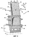
Фиг.2 - перспективное изображение части роторного узла промышленной газотурбинной установки по фиг.1, на котором часть роторного узла удалена, чтобы показать часть роторного диска и охлаждаемую лопатку ротора.FIG. 2 is a perspective view of a portion of a rotor assembly of the industrial gas turbine plant of FIG. 1, in which a portion of the rotor assembly is removed to show a portion of the rotor disk and a cooled rotor blade.
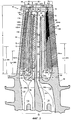
На фиг.3 лопатка по фиг.2 представлена в продольном сечении, чтобы показать структуру ее внутреннего пространства.In Fig.3, the blade of Fig.2 is presented in longitudinal section to show the structure of its internal space.
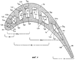
Фиг.4 соответствует сечению лопатки поперечной плоскостью, которая на фиг.3 проходит на уровне L1, т.е. рассекает лопатку на высоте, примерно соответствующей 40% ее полной длины, и показывает передний петлевой канал, задний петлевой канал и третий канал в области входной кромки; обозначена также минимальная ширина канала, измеряемая в плоскости, проходящей через хорду пера лопатки.Figure 4 corresponds to the cross section of the blade by a transverse plane, which in figure 3 extends at level L1, i.e. dissects the scapula at a height approximately equal to 40% of its full length, and shows the front loop channel, the rear loop channel and the third channel in the region of the input edge; the minimum channel width, measured in the plane passing through the chord of the feather blade, is also indicated.
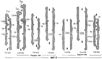
Фиг.5 представляет собой схематичное изображение сечения части петлевых каналов, иллюстрирующее набор выступов, расположенных на каждом отрезке каналов с заданным взаимным смещением по сечению пера, которое для ясности понимания изображено неполностью.5 is a schematic illustration of a section of part of the loop channels, illustrating a set of protrusions located on each segment of the channels with a given mutual offset over the cross section of the pen, which is not depicted for clarity of understanding.
На фиг.6 представлено схематичное изображение сечения частей петлевых каналов, показанных на фиг.5, иллюстрирующее относительную высоту выступов по сравнению с минимальной высотой канала.FIG. 6 is a schematic cross-sectional view of portions of the loop channels shown in FIG. 5, illustrating the relative height of the protrusions compared to the minimum height of the channel.
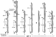
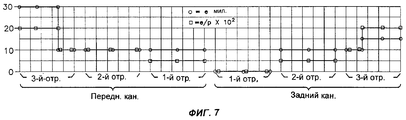
На фиг.7 в графической форме представлены высота выступов в милах (1 мил=0,025 мм), а также безразмерная величина, соответствующая отношению высоты выступа к шагу смещения, умноженному на 100, для последовательно соединенных отрезков переднего и заднего петлевых каналов.7 shows in graphical form the height of the protrusions in miles (1 mil = 0.025 mm), as well as the dimensionless value corresponding to the ratio of the height of the protrusion to the offset
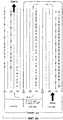
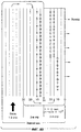
На фиг.8А и 8В приведены схематичные изображения переднего и заднего петлевых каналов, аналогичные изображениям этих каналов на фиг.7. Здесь все три отрезка в каждом канале показаны прилежащими друг к другу. На изображения каналов наложены графические представления высоты выступов (в милах) и безразмерное отношение высоты выступа к шагу смещения, умноженное на 100.On figa and 8B shows a schematic image of the front and rear loop channels, similar to the images of these channels in Fig.7. Here, all three segments in each channel are shown adjacent to each other. Graphic representations of the height of the protrusions (in miles) and the dimensionless ratio of the height of the protrusion to the offset
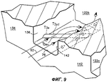
На фиг.9 дано схематичное частичное перспективное изображение части одного из каналов на виде по направлению потока охлаждающего воздуха. Здесь иллюстрируется соотношение между выступом и смежными внутренними структурами пера лопатки, а также траекторией потока охлаждающего воздуха.Figure 9 is a schematic partial perspective view of part of one of the channels in a view in the direction of flow of cooling air. This illustrates the relationship between the protrusion and adjacent internal structures of the blade pen, as well as the flow path of the cooling air.
Осуществление изобретенияThe implementation of the invention
На фиг.1 представлено схематичное перспективное изображение с частичным вырывом, иллюстрирующее в собранном положении турбоагрегат 10, включающий в себя промышленную газотурбинную установку 12. В состав турбоагрегата входит корпус, представленный стенкой 14 и имеющий воздухозаборное окно для впуска воздуха 16 внутрь корпуса, а также выпускное окно 18 для вывода из корпуса выхлопных газов. Промышленная газотурбинная установка 12 имеет в своем составе компрессорную секцию 22, камеру 24 (секцию) сгорания и турбинную секцию 26, в состав которой входит турбина (не изображена). У промышленной газотурбинной установки имеется роторный узел с валом (не изображен), ориентированным по оси А. Данный вал передает энергию в компрессорную секцию; кроме того, по нему выхлопные газы поступают к турбине для приведения ее во вращение. Турбина связана вторым валом 28 с электрической машиной, такой как генератор 32 для передачи этому генератору механической энергии вращения.Figure 1 presents a schematic perspective view with a partial tear-out, illustrating in the assembled position the
Контур 34 для рабочей газовой среды проходит через компрессорную секцию 33, секцию 24 сгорания и турбинную секцию 26. Рабочая газовая среда в виде воздуха протекает через компрессорную секцию, в которой происходит сжатие газов. В камере сгорания воздух смешивается с топливом и результирующая смесь сжигается с приданием газам дополнительной энергии. Горячие рабочие газы под высоким давлением расширяются в турбинной секции и приводят во вращение роторный узел. Энергия вращения используется для сжатия газов в компрессорной секции, которые, как было указано, затем приводят в действие турбину. Меньшая часть рабочих газов (воздуха) после сжатия в компрессорной секции подается к турбинной секции для охлаждения критических компонентов этой секции.The
На фиг.2 дано перспективное изображение части роторного узла 36, входящего в промышленную газотурбинную установку 12, показанную на фиг.1. Роторный узел включает в себя диск 38 ротора (роторный диск) и рабочую лопатку (лопатку ротора) 42, которая закреплена на роторном диске. У лопатки ротора имеется наружная поверхность 44 и внутренняя поверхность 46. Охлаждаемая лопатка ротора характеризуется продольным направлением DC ориентации своего пера и поперечным направлением Ds, соответствующим хорде пера лопатки. При работе турбины охлаждаемая лопатка ротора находится в потоке горячей рабочей среды.Figure 2 is a perspective view of part of the
Охлаждающий воздух течет от компрессорной секции 22 к источнику охлаждающего воздуха, представленному на фиг.2 зоной 48 подачи охлаждающего воздуха для охлаждения лопатки 42 ротора. Внутренняя часть 46 лопатки выполнена с возможностью приема охлаждающего воздуха для охлаждения лопатки ротора. Охлаждение необходимо для того, чтобы удерживать рабочую температуру лопатки ротора в пределах, которые являются допустимыми для материала, из которого она изготовлена.Cooling air flows from the compressor section 22 to the cooling air source shown in FIG. 2 by the cooling
Охлаждаемая лопатка ротора имеет внутренний край 52 и наружный край 54 с вершинной зоной 56, расположенной на наружном краю 54. Корневая часть (хвостовик) 58 у внутреннего края 52 лопатки ротора обеспечивает крепление лопатки ротора к роторному диску. У лопатки ротора имеются также полка (платформа) 62 и перо 64, отходящее в наружном направлении от полки. У пера 64 лопатки имеется продольная ось (не изображена), расположенная перпендикулярно оси А газотурбинной установки (т.е. вертикально на фиг.2). Перо лопатки образовано множеством участков аэродинамического профиля, которые ориентированы вдоль хорды пера и наложены друг на друга в направлении продольной оси. У пера 64 имеется входная кромка 66 и зона 68 вблизи входной кромки, которая отходит от входной кромки 66 в направлении назад. Перо имеет также выходную кромку 72 и область 74 вблизи выходной кромки, которая отходит от выходной кромки в направлении вперед. У пера имеется выпуклая боковая сторона 76, называемая спинкой, и вогнутая боковая сторона 78, называемая корытом (см. фиг.4). Каждая из этих сторон расположена между областью вблизи входной кромки (называемую также "областью входной кромки") и областью вблизи выходной кромки (называемую также "областью выходной кромки"). У пера можно выделить также среднюю область 82, которая расположена между областями вблизи входной и выходной кромок.The cooled rotor blade has an
На фиг.3 лопатка ротора по фиг.2 представлена на виде спереди и в продольном сечении для того, чтобы проиллюстрировать структуру внутренней поверхности 46 лопатки. Корыто 78 соединено со спинкой 76 в области 68 передней кромки с образованием структуры в форме лопасти аэродинамического профиля, соответствующей передней стенке 84. Аналогично, корыто 78 соединено со спинкой 76 в области 74 задней кромки с образованием структуры в форме лопасти аэродинамического профиля, соответствующей задней стенке 86. Между корытом 78 и спинкой 76, взаимно смещенными вдоль хорды пера, образована полость 88, предназначенная для подачи в нее охлаждающего воздуха от зоны 48 подачи.In FIG. 3, the rotor blade of FIG. 2 is shown in front and in longitudinal section in order to illustrate the structure of the
У лопатки 42 ротора имеется передний проточный контур 92 для охлаждающего воздуха и задний проточный контур 94 для охлаждающего воздуха. Эти контуры проходят через стенку 96 хвостовика 58, ориентированную в направлении хорды пера. В вершинной зоне 56 пера имеется верхняя стенка 98. Множество выпускных отверстий, представленных на фиг.3 отверстиями 102, 104 и 106 и выполненных в стенке 98, обеспечивает сообщение полости 88 для охлаждающего воздуха с наружной поверхностью пера у верхней (наружной) стенки пера 64 лопатки. Задняя стенка 86 пера также снабжена множеством охлаждающих отверстий 108, расположенных со смещением в продольном направлении вдоль стенки 86. Эти отверстия также обеспечивают сообщение полости 88 с наружной поверхностью пера.The
Как показано на фиг.3, в хвостовике выполнен первый проход 112 для охлаждающего воздуха, обеспечивающий связь лопатки по потоку охлаждающей текучей среды (воздуха) с компрессорной секцией 122 через зону 48 подачи. Этот первый проход 112 включает в себя первую камеру 114, первую проточную зону, расположенную по ходу потока воздуха перед первой камерой 114, и вторую проточную зону, расположенную за камерой 114 и имеющую больший объем, чем первая зона. В хвостовике выполнен также второй охлаждающий проход 116, который также обеспечивает связь лопатки по потоку охлаждающего воздуха с источником сжатого воздуха. Этот второй охлаждающий проход 116 включает в себя вторую камеру 118, первую проточную зону, расположенную по ходу потока перед второй камерой 118, и вторую проточную зону, расположенную за камерой 118 и имеющую больший объем, чем первая зона. Зона 48 подачи обеспечивает питание охлаждающим воздухом обоих названных проходов при одинаковом давлении. В альтернативном варианте зона подачи может содержать переднюю часть и заднюю часть, отделенные друг от друга и снабжаемые охлаждающим воздухом от компрессорной секции под различными давлениями.As shown in FIG. 3, a
На фиг.4 показано, в увеличенном масштабе, сечение лопатки поперечной плоскостью, которая на фиг.3 проходит на уровне L1, соответствующем примерно 40% длины S пера лопатки (L1=0,38S). Как показано на фиг.3 и 4, лопатка ротора имеет первый (передний) петлевой канал 122, второй (задний) петлевой канал 124 и третий канал 126 вблизи входной кромки пера. На фиг.4 показаны минимальные значения Hm ширины каждого канала в различных участках 1-7 сечения пера лопатки. Как видно из фиг.4, значения Hm измеряются от спинки 76 пера в направлении корыта 78 пера вдоль линии, перпендикулярной спинке пера. В названных каналах имеются ленточные выступы Т, изображенные в иллюстративных целях в увеличенном масштабе.Figure 4 shows, on an enlarged scale, the cross section of the blade with a transverse plane, which in FIG. 3 extends at a level L1 corresponding to approximately 40% of the length S of the blade feather (L1 = 0.38S). As shown in FIGS. 3 and 4, the rotor blade has a first (front)
У пера лопатки имеются также ребра, которые ориентированы в продольном направлении и расположены от спинки 76 до корыта 78 пера. Они образуют внутренние структуры пера, примыкающие к петлевым каналам и формирующие их стенки. Кроме того, передняя стенка 84 пера вблизи его входной кромки, примыкающая к третьему каналу 126, расположенному у входной кромки, а также задняя стенка 86 вблизи выходной кромки пера, примыкающая к заднему петлевому каналу 124, тоже образуют внутренние структуры пера, формирующие стенки названных каналов. Каждый из петлевых каналов имеет три участка или отрезка (а именно отрезки 122а, 122b, 122с для переднего петлевого канала и 124а, 124b, 124с для заднего петлевого канала). Каждый отрезок ориентирован в продольном направлении и, как было указано, ограничен ребрами.The feather blade also has ribs that are oriented in the longitudinal direction and are located from the back 76 to the
Первое ребро 132, ориентированное в продольном направлении, расположено в средней части 82 пера и проходит до стенки 98 в его вершинной зоне. Это ребро делит полость 88 на переднюю часть 88а и на заднюю часть 88b. Передняя часть 88а полости снабжена вторым ребром 134, которое расположено от стенки 96 хвостовика лопатки до стенки 98 в вершинной зоне пера. Это ребро пространственно отделено от входной кромки 66, так что между ними образуется третий канал 126.The first rib 132, oriented in the longitudinal direction, is located in the
Третье ребро 136, отходящее от стенки 96 хвостовика, пространственно отделено в направлении хорды пера от первого ребра 132, так что между ними располагается первый отрезок 122а переднего петлевого канала 122. Третье ребро 132 ограничивает также второй отрезок 122b этого канала. Третье ребро 132 пространственно отделено от верхней стенки 98, благодаря чему между ними образуется первое колено 138, сопрягающее первый и второй отрезки переднего петлевого канала.The
Четвертое ребро 142, отходящее от верхней стенки 98 вершинной зоны пера, пространственно смещено в направлении хорды пера относительно третьего ребра 136 и вместе с ним ограничивает второй отрезок 122b. Четвертое ребро пространственно смещено также в направлении хорды пера относительно второго ребра 134 и вместе с ним ограничивает третий отрезок 122с. Далее, четвертое ребро пространственно отделено от стенки хвостовика, за счет чего между ними формируется второе колено 144 для переднего петлевого канала 122.The
В задней части 88b полости имеется пятое ребро 146, отходящее от стенки 98 хвостовика. Пятое ребро пространственно смещено в направлении хорды пера относительно первого ребра и вместе с ним ограничивает первый отрезок 124а заднего петлевого канала 124. Пятое ребро ограничивает также второй отрезок 124b этого канала. Далее, пятое ребро пространственно отделено от стенки вершинной части пера, за счет чего между ними формируется первое колено 148 для заднего петлевого канала.At the rear of the
В задней части пера имеется шестое ребро 152, которое выступает в продольном направлении из стенки 98 вершинной зоны пера. Шестое ребро пространственно смещено в направлении хорды пера относительно пятого ребра и вместе с ним ограничивает второй отрезок 124b. Шестое ребро пространственно смещено также в направлении хорды пера относительно задней стенки 86 пера и вместе с ним ограничивает второй отрезок 124b. Далее, четвертое ребро пространственно отделено от стенки хвостовика, за счет чего между ними формируется второе колено 154 для заднего петлевого канала 122.At the rear of the pen there is a
У каждого из каналов, в том числе у переднего петлевого канала 122, у заднего петлевого канала 124 и у третьего канала 126 вблизи передней кромки пера имеется выходной конец 158, 162, 156 соответственно. Каждый выходной конец канала сообщается по потоку с соответствующим ему выпускным отверстием 104, 106, 102. Названные отверстия проходят через вершинную зону 56 пера, сообщаясь с наружной поверхностью пера 44. Таким образом, выпускное отверстие обеспечивает сообщение выходного конца соответствующего канала с наружной поверхностью пера.Each channel, including the
Каждый из каналов, включая передний петлевой канал 122, задний петлевой канал 124 и третий канал 126 вблизи передней кромки пера снабжен, по меньшей мере, одним набором ленточных выступов Ts со стороны спинки пера и, по меньшей мере, одним набором выступов Тр со стороны корыта. Таким образом, для каждого канала сформированы, по меньшей мере, два набора выступов. В варианте, представленном на чертежах (см., например, фиг.4, 6), передний петлевой канал снабжен выступами со стороны спинки и со стороны корыта в каждом из своих отрезков. Набор выступов почти полностью (на 90%) перекрывает длину соответствующего отрезка. Однако некоторые преимущества, создаваемые настоящим изобретением, могут быть реализованы и при меньшем перекрытии.Each of the channels, including the
Итак, первый отрезок 122а снабжен наборами Т4р и T4s выступов, выполненными соответственно на его сторонах, примыкающих к корыту и спинке пера. Второй отрезок 122b снабжен наборами Т3р и T3s выступов, выполненными соответственно на его сторонах, примыкающих к корыту и спинке пера. Третий отрезок 122с снабжен наборами Т2р и T2s выступов, выполненными соответственно на его сторонах, примыкающих к корыту и спинке пера. У третьего отрезка имеется первый участок 122са, к которому поступает охлаждающий воздух из второго отрезка, и второй участок 122cb, расположенный по ходу потока за первым участком (фиг.6). При этом наборы ленточных выступов в третьем отрезке, расположенные на его втором участке 122cb, имеют значения высоты выступа и отношения высоты выступа к шагу выступов, превышающие аналогичные значения в тех же наборах, расположенных на его первом участке 122са, а также в наборах для второго отрезка 122b того же контура.So, the
Задний петлевой канал не имеет выступов на своем первом отрезке. Его второй и третий отрезки снабжены наборами ленточных выступов. В частности, второй отрезок снабжен наборами Т6р и T6s ленточных выступов, выполненными соответственно на его сторонах, примыкающих к корыту и спинке пера. Третий отрезок снабжен наборами Т7р и T7s ленточных выступов, выполненными соответственно на его сторонах, примыкающих к корыту и спинке пера. При этом у третьего отрезка имеется входная по потоку часть и выходная часть, причем выступы выходной части несколько отличаются от выступов входной части.The rear loop channel has no protrusions in its first segment. Its second and third segments are equipped with sets of tape protrusions. In particular, the second segment is provided with sets of tape protrusions T6p and T6s made respectively on its sides adjacent to the trough and the back of the pen. The third segment is equipped with sets of tape protrusions T7p and T7s made respectively on its sides adjacent to the trough and back of the pen. In this case, the third segment has an upstream part and an output part, and the protrusions of the output part are somewhat different from the protrusions of the inlet part.
Выступы Т на каждой стороне, примыкающей к спинке 76 или корыту 78 пера, расположены с взаимным смещением в продольном направлении, имеющем определенный шаг, а также со смещением относительно выступов, расположенных на противоположной стороне канала (фиг.6). Для каждого ленточного выступа могут быть определены передний (по направлению потока охлаждающего воздуха) и задний края, а также стенка канала, из которой он выступает. Например, на отрезке 122b (см. фиг.9) имеется ленточный выступ Т3 (точнее T3s) на боковой стенке, соответствующей спинке пера, причем у этого выступа имеется передний край (T3su) и задний край (T3sd). Выступы каждого набора параллельны друг другу и параллельны выступам на противоположной боковой стенке канала. Каждый ленточный выступ характеризуется высотой Н, измеряемой от примыкающей к нему части боковой стенки и далее обозначаемой как "e", и отношением (e/p) высоты выступа к шагу выступов, характеризующему их взаимное смещение. Это отношение может быть нормализовано путем умножения на 100. Каждый ленточный выступ со стороны своего входного края образует острый угол, примерно равный 45°, с примыкающей к нему внутренней структурой пера, ограничивающей петлевой канал.The protrusions T on each side adjacent to the
На некоторых участках канала выступы могут быть удалены для того, чтобы обеспечить возможность измерения толщины стенки лопатки в процессе ее изготовления. Это решение позволяет также осуществлять контроль качества изготовления пера лопатки. Соответствующие участки отмечены индексом Q (фиг.3). Удаление части или всего выступа для указанной цели не рассматривается как изменение шага в наборе соответствующих выступов. В типичном случае удаление выступа (полностью или частично) для целей контроля качества будет иметь место на трех участках каждой боковой стенки каждого отрезка канала.On some sections of the channel, the protrusions can be removed in order to enable the measurement of the wall thickness of the blade during its manufacture. This solution also allows you to control the quality of manufacture of the feather blades. The corresponding sections are indicated by the index Q (figure 3). Removing part or all of a protrusion for a specified purpose is not considered a change in the step in the set of corresponding protrusions. In a typical case, the removal of the protrusion (in whole or in part) for quality control purposes will take place in three sections of each side wall of each channel section.
В приводимой ниже таблице для одного из вариантов настоящего изобретения приводятся значения высоты (HT) выступов, шага (PT) смещения и нормализованного отношения ((e/p)×100) высоты выступа к шагу выступов. Эти данные приводятся для ленточных выступов, примыкающих к продольно внутренней и продольно внешней частям каждого набора выступов. В таблице приведены значения минимального расстояния Hp (т.е. Hm) между боковыми стенками со стороны спинки и корыта пера, измеренные в осевом направлении на высоте, составляющей примерно 40% высоты S пера (Ls=0,38S - см. фиг.3 и 4).In the table below, for one embodiment of the present invention, the values of the height (H T ) of the protrusions, the pitch (P T ) of the offset and the normalized ratio ((e / p) × 100) of the height of the protrusion to the pitch of the protrusions are given. These data are given for tape protrusions adjacent to the longitudinally internal and longitudinally external parts of each set of protrusions. The table shows the values of the minimum distance Hp (i.e., Hm) between the side walls from the back and the side of the pen, measured in the axial direction at a height of approximately 40% of the height S of the pen (Ls = 0.38S - see Fig. 3 and 4).
Фиг.5 представляет собой схематичное изображение сечения части петлевых каналов, иллюстрирующее наборы ленточных выступов, расположенных на каждом отрезке каналов с заданным взаимным смещением по лине пера, которое для ясности понимания изображено неполностью. Плоскость частичного сечения соответствует линиям 5-5 на фиг.3. Более точно, для участков пера лопатки, соответствующих позициям 1, 3, 4 и 5 в направлении хорды пера, считая от входной кромки, плоскость сечения расположена на высоте, составляющей примерно 40% полной длины пера (S=0,38). Для позиций 2 и 7 в направлении хорды пера плоскость сечения расположена на высоте, составляющей соответственно примерно 30% (S=0,29) и 50% (S=0,47) полной длины пера. Стрелки на фиг.5 показывают направление движения воздуха в каналах.5 is a schematic sectional view of part of the loop channels, illustrating sets of tape protrusions located on each section of channels with a given mutual offset along the line of the pen, which for clarity of understanding is depicted incompletely. The partial section plane corresponds to lines 5-5 in FIG. 3. More precisely, for portions of the blade pen corresponding to
Как показано на фиг.5, каждый ленточный выступ имеет выпуклый цилиндрический вершинный участок с радиусом, составляющим половину высоты выступа (Rvx=Н/2=e/2), и вогнутые участки T3su T3sd (см. также фиг.9), расположенные соответственно на передней и задней сторонах выступа и обеспечивающие переход по цилиндрической поверхности к боковой стенке канала. Радиус этих переходных участков равен половине высоты выступа (Rav=Н/2=e/2). Высота Н(e) выступов в первом, втором и третьем каналах выбрана в интервале, приближенно составляющем 0,25-0,76 мм (0,25 мм≤e, Н≤0,76 мм).As shown in FIG. 5, each tape protrusion has a convex cylindrical apical portion with a radius equal to half the height of the protrusion (Rvx = H / 2 = e / 2), and concave sections T3su T3sd (see also FIG. 9) located respectively on the front and rear sides of the protrusion and providing a transition along a cylindrical surface to the side wall of the channel. The radius of these transition sections is equal to half the height of the protrusion (Rav = N / 2 = e / 2). The height H (e) of the protrusions in the first, second and third channels is selected in the range of approximately 0.25-0.76 mm (0.25 mm≤e, H≤0.76 mm).
На фиг.6 представлено схематичное изображение сечения частей петлевых каналов, показанных на фиг.5, иллюстрирующее относительную высоту выступов по сравнению с минимальной высотой канала и шагом смещения выступов.FIG. 6 is a schematic cross-sectional view of portions of the loop channels shown in FIG. 5, illustrating the relative height of the protrusions compared to the minimum channel height and the offset pitch of the protrusions.
На фиг.7 в графической форме представлены высота выступов в милах, а также безразмерная величина, соответствующая нормализованному отношению высоты выступа к шагу смещения, для последовательно соединенных отрезков 122а, 122b, 122с переднего петлевого канала и для последовательно соединенных отрезков 124а, 124b, 122с заднего петлевого канала.7 shows in graphical form the height of the protrusions in miles, as well as the dimensionless value corresponding to the normalized ratio of the height of the protrusion to the offset step, for the series-connected segments of the
На фиг.8А и 8В приведены схематичные изображения переднего и заднего петлевых каналов, аналогичные изображениям этих каналов на фиг.7. Здесь все три отрезка в каждом канале показаны прилежащими друг к другу. На изображения каналов наложены графические представления высоты выступа (в милах) и безразмерное нормализованное отношение высоты выступа к шагу смещения.On figa and 8B shows a schematic image of the front and rear loop channels, similar to the images of these channels in Fig.7. Here, all three segments in each channel are shown adjacent to each other. Graphic representations of the height of the protrusion (in miles) and the dimensionless normalized ratio of the height of the protrusion to the offset step are superimposed on the channel images.
На фиг.9 дано схематичное частичное перспективное изображение части одного из каналов. Здесь иллюстрируется соотношение между ленточным выступом и смежными внутренними структурами пера лопатки, а также траекторией потока охлаждающего воздуха. Как показано на фиг.9, со своей передней стороны выступ расположен под острым углом к ребру, ближайшему к соответствующей кромке пера. В результате часть охлаждающего воздуха отклоняется в сторону данной кромки и в канал с движением потока в направлении против часовой стрелки. Это повышает турбулентность воздуха в канале и усиливает теплопередачу (т.е. отбор тепла) от ребра, ближайшего к кромке пера.Figure 9 is a schematic partial perspective view of part of one of the channels. This illustrates the relationship between the tape protrusion and the adjacent internal structures of the blade pen, as well as the flow path of the cooling air. As shown in FIG. 9, from its front side, the protrusion is at an acute angle to the rib closest to the corresponding edge of the pen. As a result, a part of the cooling air deviates towards this edge and into the channel with the flow in the counterclockwise direction. This increases air turbulence in the channel and enhances heat transfer (i.e., heat removal) from the rib closest to the edge of the pen.
В рабочих условиях, т.е. в процессе работы газотурбинной установки, охлаждаемой рабочей лопатке передается тепло от потока рабочей среды. Тепловой поток является более интенсивным в областях вблизи входной кромки и выходной кромки и менее интенсивным в средней части пера лопатки. Охлаждающий воздух протекает в средней части лопатки по переднему петлевому каналу 122 и по заднему петлевому каналу 124.Under operating conditions, i.e. during the operation of the gas turbine installation, the cooled working blade transfers heat from the flow of the working medium. The heat flux is more intense in areas near the inlet edge and outlet edge and less intense in the middle of the blade feather. Cooling air flows in the middle part of the blade along the
Первый отрезок 122а переднего петлевого канала снабжен ленточными выступами, но в первом отрезке 124а заднего петлевого канала выступы отсутствуют. Передний петлевой канал отводит от средней части пера большее количество тепла, чем задний петлевой канал. В результате задний петлевой канал создает меньше помех для протекания потока и имеет меньшие потери давления, под действием которого поток продвигается через третий отрезок этого канала. Данное обстоятельство является важным, поскольку третий отрезок заднего петлевого канала имеет меньшее сечение, чем третий отрезок переднего петлевого канала. Кроме того, поскольку в первом отрезке нет выступов, охлаждающий воздух в заднем петлевом канале нагревается меньше, чем в переднем. В результате охлаждающий воздух в заднем петлевом канале имеет большую способность отвода тепла от области задней кромки пера, чем охлаждающий воздух с более высокой температурой, которую поток в заднем петлевом канале имел бы при наличии выступов в первом отрезке этого канала. Таким образом, конструкция лопатки по изобретению обеспечивает отвод тепла от средней области пера при одновременном повышении способности охлаждающего воздуха (как в отношении температуры, так и давления) к охлаждению критической области задней кромки.The
Наборы выступов в отрезках переднего и заднего петлевых каналов, а именно в первом отрезке 122а и во вторых отрезках 122b, 124b, не используют увеличение высоты выступа или отношения высоты выступа к шагу смещения выступов по длине соответствующего отрезка или канала в целом. Такая конструкция упрощает подготовку пресс-форм, применяемых при изготовлении лопатки ротора, и увеличивает удобство контроля в процессе изготовления пера лопатки.The sets of protrusions in the segments of the front and rear loop channels, namely in the
Передний петлевой канал 122 и задний петлевой канал 124 в своих третьих отрезках 122с, 124с содержат выступы, у которых как высота выступа, так и отношение высоты к шагу смещения имеют, по меньшей мере, на вторых по ходу потока участках 122cb, 124cb третьего отрезка более высокие значения, чем аналогичные значения для вторых отрезков 122b, 124b. Тем самым обеспечивается большее повышение эффективности теплоотдачи при переходе к третьему отрезку по сравнению с тем, которое имеет место при переходе от первого отрезка ко второму в процессе движения потока охлаждающего воздуха.The
Кроме того, наборы ленточных выступов, которые имеются в третьем отрезке как переднего, так и заднего петлевых каналов на вторых по ходу потока участках 122cb, 124cb, имеют более высокие значения высоты выступов и отношения высоты выступов к шагу смещения, чем на первых участках 122са, 124са и чем в соответствующих наборах во втором отрезке 122b, 124b. Наборы ленточных выступов во втором отрезке 122b, 124b имеют такие значения высоты выступов и отношения этой высоты к шагу смещения выступов, которые превышают аналогичные характеристики для соответствующих характеристик выступов в первом отрезке 122а, 124а. Благодаря этому обеспечивается повышение эффективности теплоотдачи во втором и в третьем отрезках по направлению движения потока. Таким образом, данная конструкция лопатки обеспечивает баланс между необходимостью отбирать большее количество тепла от области передней кромки и необходимостью отводить меньшее количество тепла от средней части пера.In addition, the sets of tape protrusions that are present in the third segment of both the front and rear loop channels in the second upstream portions 122cb, 124cb have higher values of the height of the protrusions and the ratio of the height of the protrusions to the offset step than in the
Третий канал 126, расположенный между входной кромкой 66 и третьим отрезком 122с переднего петлевого канала, имеет первый участок 126а, смежный с хвостовиком 58, и второй участок 126b, смежный с вершиной 56 пера. В третьем канале высота e выступа и отношение (e/p) высоты выступа к шагу p выступов выбраны большими, чем в первом отрезке переднего петлевого канала. Третий канал, в дополнение к переднему петлевому каналу, обеспечивает отвод тепла от области 68 входной кромки. Этот дополнительный отвод тепла предусматривается с учетом того, что передний петлевой канал получает большее количество тепла от средней части пера, поскольку в его первом отрезке (в отличие от заднего петлевого канала) имеются выступы.The
Таким образом, повышенная способность отводить тепло, присущая более холодному воздуху в заднем петлевом канале, обусловлена конструкцией переднего петлевого канала и, в известной степени, наличием третьего канала. Как показано на фиг.9, наборы ленточных выступов в отрезках первого и второго петлевых каналов образуют своим передним краем острый угол с внутренней структурой пера, ограничивающей канал со стороны, которая ближе расположена к области соответствующей кромки. Это приводит к тому, что часть охлаждающего воздуха течет в первом канале в сторону той внутренней структуры, которая расположена ближе к соответствующей кромке пера. Это также способствует увеличению способности отводить тепло в областях кромок пера лопатки. Третий канал содержит такие ленточные выступы, каждый из которых своей передней стороной образует острый угол со вторым ребром для отвода в рабочих условиях части потока охлаждающего воздуха в направлении самого переднего ребра, ограничивающего передний петлевой канал. Таким образом, и в этом случае способность отводить тепло, присущая третьему каналу, дополняет аналогичную способность, присущую переднему петлевому каналу в области 68 входной кромки пера.Thus, the increased ability to remove heat inherent in colder air in the rear loop channel is due to the design of the front loop channel and, to a certain extent, the presence of a third channel. As shown in Fig. 9, the sets of tape protrusions in the segments of the first and second loop channels form an acute angle with their front edge with the internal structure of the pen bounding the channel from the side closer to the region of the corresponding edge. This leads to the fact that part of the cooling air flows in the first channel in the direction of the internal structure, which is located closer to the corresponding edge of the pen. It also helps to increase the ability to remove heat in the areas of the edges of the feather blade. The third channel contains such tape protrusions, each of which with its front side forms an acute angle with a second rib to divert under operating conditions part of the flow of cooling air in the direction of the very front rib bounding the front loop channel. Thus, in this case as well, the ability to remove heat inherent in the third channel complements the similar ability inherent in the front loop channel in the
Хотя настоящее изобретение было описано на примерах его конкретных вариантов, для специалистов в данной области будет понятно, что в форму и детали осуществления изобретения могут быть внесены изменения, не выходящие за границы идеи и объема изобретения.Although the present invention has been described with examples of specific embodiments thereof, it will be understood by those skilled in the art that changes may be made to the form and details of the invention without departing from the spirit and scope of the invention.
Claims (18)
Applications Claiming Priority (2)
| Application Number | Priority Date | Filing Date | Title |
|---|---|---|---|
| US10/014,952 US6672836B2 (en) | 2001-12-11 | 2001-12-11 | Coolable rotor blade for an industrial gas turbine engine |
| US10/014,952 | 2001-12-11 |
Publications (2)
| Publication Number | Publication Date |
|---|---|
| RU2002132867A RU2002132867A (en) | 2004-07-20 |
| RU2275508C2 true RU2275508C2 (en) | 2006-04-27 |
Family
ID=21768742
Family Applications (1)
| Application Number | Title | Priority Date | Filing Date |
|---|---|---|---|
| RU2002132867/06A RU2275508C2 (en) | 2001-12-11 | 2002-12-09 | Cooled blade of rotor for industrial gas-turbine plant (versions) |
Country Status (6)
| Country | Link |
|---|---|
| US (1) | US6672836B2 (en) |
| EP (1) | EP1319803B1 (en) |
| JP (1) | JP2003193805A (en) |
| CN (1) | CN1313706C (en) |
| DE (1) | DE60220875T2 (en) |
| RU (1) | RU2275508C2 (en) |
Cited By (2)
| Publication number | Priority date | Publication date | Assignee | Title |
|---|---|---|---|---|
| RU2805105C2 (en) * | 2019-05-09 | 2023-10-11 | Сафран | Turbomachine blade with improved cooling |
| US11946387B2 (en) | 2019-06-13 | 2024-04-02 | Safran Aircraft Engines | Turbine engine blade with improved cooling |
Families Citing this family (70)
| Publication number | Priority date | Publication date | Assignee | Title |
|---|---|---|---|---|
| GB0222352D0 (en) * | 2002-09-26 | 2002-11-06 | Dorling Kevin | Turbine blade turbulator cooling design |
| CN1301365C (en) * | 2003-07-16 | 2007-02-21 | 沈阳黎明航空发动机(集团)有限责任公司 | Turbine machine matched with gas turbine |
| US6966756B2 (en) * | 2004-01-09 | 2005-11-22 | General Electric Company | Turbine bucket cooling passages and internal core for producing the passages |
| US7114916B2 (en) | 2004-02-09 | 2006-10-03 | United Technologies Corporation | Tailored turbulation for turbine blades |
| US6997675B2 (en) * | 2004-02-09 | 2006-02-14 | United Technologies Corporation | Turbulated hole configurations for turbine blades |
| EP1577497A1 (en) * | 2004-03-01 | 2005-09-21 | ALSTOM Technology Ltd | Internally cooled turbomachine blade |
| US20050265839A1 (en) * | 2004-05-27 | 2005-12-01 | United Technologies Corporation | Cooled rotor blade |
| GB0418906D0 (en) * | 2004-08-25 | 2004-09-29 | Rolls Royce Plc | Internally cooled aerofoils |
| EP1630354B1 (en) | 2004-08-25 | 2014-06-18 | Rolls-Royce Plc | Cooled gas turbine aerofoil |
| US7153096B2 (en) | 2004-12-02 | 2006-12-26 | Siemens Power Generation, Inc. | Stacked laminate CMC turbine vane |
| US7255535B2 (en) | 2004-12-02 | 2007-08-14 | Albrecht Harry A | Cooling systems for stacked laminate CMC vane |
| US7198458B2 (en) | 2004-12-02 | 2007-04-03 | Siemens Power Generation, Inc. | Fail safe cooling system for turbine vanes |
| US7163373B2 (en) * | 2005-02-02 | 2007-01-16 | Siemens Power Generation, Inc. | Vortex dissipation device for a cooling system within a turbine blade of a turbine engine |
| US7575414B2 (en) * | 2005-04-01 | 2009-08-18 | General Electric Company | Turbine nozzle with trailing edge convection and film cooling |
| US7296972B2 (en) * | 2005-12-02 | 2007-11-20 | Siemens Power Generation, Inc. | Turbine airfoil with counter-flow serpentine channels |
| US7431562B2 (en) * | 2005-12-21 | 2008-10-07 | General Electric Company | Method and apparatus for cooling gas turbine rotor blades |
| US7445432B2 (en) * | 2006-03-28 | 2008-11-04 | United Technologies Corporation | Enhanced serpentine cooling with U-shaped divider rib |
| GB2441148A (en) * | 2006-08-23 | 2008-02-27 | Rolls Royce Plc | Gas turbine engine component with coolant passages |
| US7547191B2 (en) * | 2006-08-24 | 2009-06-16 | Siemens Energy, Inc. | Turbine airfoil cooling system with perimeter cooling and rim cavity purge channels |
| US7823374B2 (en) * | 2006-08-31 | 2010-11-02 | General Electric Company | Heat transfer system and method for turbine engine using heat pipes |
| US20080110024A1 (en) * | 2006-11-14 | 2008-05-15 | Reilly P Brennan | Airfoil casting methods |
| US7762774B2 (en) * | 2006-12-15 | 2010-07-27 | Siemens Energy, Inc. | Cooling arrangement for a tapered turbine blade |
| GB0700499D0 (en) * | 2007-01-11 | 2007-02-21 | Rolls Royce Plc | Aerofoil configuration |
| US7785070B2 (en) * | 2007-03-27 | 2010-08-31 | Siemens Energy, Inc. | Wavy flow cooling concept for turbine airfoils |
| US7967567B2 (en) * | 2007-03-27 | 2011-06-28 | Siemens Energy, Inc. | Multi-pass cooling for turbine airfoils |
| US8083485B2 (en) * | 2007-08-15 | 2011-12-27 | United Technologies Corporation | Angled tripped airfoil peanut cavity |
| US20090060714A1 (en) * | 2007-08-30 | 2009-03-05 | General Electric Company | Multi-part cast turbine engine component having an internal cooling channel and method of forming a multi-part cast turbine engine component |
| US7988417B1 (en) * | 2007-11-19 | 2011-08-02 | Florida Turbine Technologies, Inc. | Air cooled turbine blade |
| US8105031B2 (en) * | 2008-01-10 | 2012-01-31 | United Technologies Corporation | Cooling arrangement for turbine components |
| US8172533B2 (en) * | 2008-05-14 | 2012-05-08 | United Technologies Corporation | Turbine blade internal cooling configuration |
| US8177507B2 (en) * | 2008-05-14 | 2012-05-15 | United Technologies Corporation | Triangular serpentine cooling channels |
| JP5189406B2 (en) | 2008-05-14 | 2013-04-24 | 三菱重工業株式会社 | Gas turbine blade and gas turbine provided with the same |
| US20100031669A1 (en) * | 2008-08-06 | 2010-02-11 | Cessna Aircraft Company | Free Turbine Generator For Aircraft |
| US8133015B2 (en) * | 2008-09-30 | 2012-03-13 | General Electric Company | Turbine nozzle for a gas turbine engine |
| ES2398303T3 (en) | 2008-10-27 | 2013-03-15 | Alstom Technology Ltd | Refrigerated blade for a gas turbine and gas turbine comprising one such blade |
| US8764379B2 (en) * | 2010-02-25 | 2014-07-01 | General Electric Company | Turbine blade with shielded tip coolant supply passageway |
| US8840371B2 (en) * | 2011-10-07 | 2014-09-23 | General Electric Company | Methods and systems for use in regulating a temperature of components |
| US8858159B2 (en) | 2011-10-28 | 2014-10-14 | United Technologies Corporation | Gas turbine engine component having wavy cooling channels with pedestals |
| EP2805018A1 (en) * | 2011-12-29 | 2014-11-26 | General Electric Company | Airfoil cooling circuit |
| US9388700B2 (en) * | 2012-03-16 | 2016-07-12 | United Technologies Corporation | Gas turbine engine airfoil cooling circuit |
| CN104204412B (en) | 2012-03-22 | 2016-09-28 | 通用电器技术有限公司 | Turbo blade |
| US9422817B2 (en) | 2012-05-31 | 2016-08-23 | United Technologies Corporation | Turbine blade root with microcircuit cooling passages |
| US20140219813A1 (en) * | 2012-09-14 | 2014-08-07 | Rafael A. Perez | Gas turbine engine serpentine cooling passage |
| US9334755B2 (en) | 2012-09-28 | 2016-05-10 | United Technologies Corporation | Airfoil with variable trip strip height |
| US9080452B2 (en) | 2012-09-28 | 2015-07-14 | United Technologies Corporation | Gas turbine engine airfoil with vane platform cooling passage |
| CN102943693A (en) * | 2012-11-29 | 2013-02-27 | 哈尔滨汽轮机厂有限责任公司 | Efficient cooling turbine movable vane of gas turbine with low-heat and medium-heat values |
| EP2971545B1 (en) * | 2013-03-11 | 2020-08-19 | United Technologies Corporation | Low pressure loss cooled blade |
| US10502065B2 (en) | 2013-06-17 | 2019-12-10 | United Technologies Corporation | Gas turbine engine component with rib support |
| US20160208620A1 (en) * | 2013-09-05 | 2016-07-21 | United Technologies Corporation | Gas turbine engine airfoil turbulator for airfoil creep resistance |
| US9551229B2 (en) * | 2013-12-26 | 2017-01-24 | Siemens Aktiengesellschaft | Turbine airfoil with an internal cooling system having trip strips with reduced pressure drop |
| WO2015160404A2 (en) * | 2014-02-13 | 2015-10-22 | United Technologies Corporation | Gas turbine engine component with separation rib for cooling passages |
| US10012090B2 (en) * | 2014-07-25 | 2018-07-03 | United Technologies Corporation | Airfoil cooling apparatus |
| US10167726B2 (en) * | 2014-09-11 | 2019-01-01 | United Technologies Corporation | Component core with shaped edges |
| US10294799B2 (en) * | 2014-11-12 | 2019-05-21 | United Technologies Corporation | Partial tip flag |
| US10156157B2 (en) * | 2015-02-13 | 2018-12-18 | United Technologies Corporation | S-shaped trip strips in internally cooled components |
| US9995146B2 (en) * | 2015-04-29 | 2018-06-12 | General Electric Company | Turbine airfoil turbulator arrangement |
| US9976425B2 (en) * | 2015-12-21 | 2018-05-22 | General Electric Company | Cooling circuit for a multi-wall blade |
| US9932838B2 (en) * | 2015-12-21 | 2018-04-03 | General Electric Company | Cooling circuit for a multi-wall blade |
| WO2017171763A1 (en) * | 2016-03-31 | 2017-10-05 | Siemens Aktiengesellschaft | Turbine airfoil with turbulating feature on a cold wall |
| FR3056631B1 (en) * | 2016-09-29 | 2018-10-19 | Safran | IMPROVED COOLING CIRCUIT FOR AUBES |
| FR3062675B1 (en) * | 2017-02-07 | 2021-01-15 | Safran Helicopter Engines | HELICOPTER TURBINE HIGH PRESSURE VENTILATED VANE INCLUDING UPSTREAM DUCT AND CENTRAL COOLING CAVITY |
| US10508548B2 (en) * | 2017-04-07 | 2019-12-17 | General Electric Company | Turbine engine with a platform cooling circuit |
| US10801724B2 (en) * | 2017-06-14 | 2020-10-13 | General Electric Company | Method and apparatus for minimizing cross-flow across an engine cooling hole |
| JP6996947B2 (en) | 2017-11-09 | 2022-01-17 | 三菱パワー株式会社 | Turbine blades and gas turbines |
| US10655476B2 (en) | 2017-12-14 | 2020-05-19 | Honeywell International Inc. | Gas turbine engines with airfoils having improved dust tolerance |
| JP7096695B2 (en) | 2018-04-17 | 2022-07-06 | 三菱重工業株式会社 | Turbine blades and gas turbines |
| US10787932B2 (en) | 2018-07-13 | 2020-09-29 | Honeywell International Inc. | Turbine blade with dust tolerant cooling system |
| JP7162514B2 (en) * | 2018-12-07 | 2022-10-28 | 三菱重工業株式会社 | Axial turbomachinery and its blades |
| CN109441555A (en) * | 2018-12-26 | 2019-03-08 | 哈尔滨广瀚动力技术发展有限公司 | A kind of marine gas turbine turbine rotor blade cooling structure |
| JP2023165485A (en) * | 2022-05-06 | 2023-11-16 | 三菱重工業株式会社 | Turbine blade and gas turbine |
Family Cites Families (16)
| Publication number | Priority date | Publication date | Assignee | Title |
|---|---|---|---|---|
| US4526512A (en) | 1983-03-28 | 1985-07-02 | General Electric Co. | Cooling flow control device for turbine blades |
| US4514144A (en) | 1983-06-20 | 1985-04-30 | General Electric Company | Angled turbulence promoter |
| GB2165315B (en) * | 1984-10-04 | 1987-12-31 | Rolls Royce | Improvements in or relating to hollow fluid cooled turbine blades |
| JP3006174B2 (en) * | 1991-07-04 | 2000-02-07 | 株式会社日立製作所 | Member having a cooling passage inside |
| US5700132A (en) | 1991-12-17 | 1997-12-23 | General Electric Company | Turbine blade having opposing wall turbulators |
| US5695322A (en) | 1991-12-17 | 1997-12-09 | General Electric Company | Turbine blade having restart turbulators |
| US5681144A (en) | 1991-12-17 | 1997-10-28 | General Electric Company | Turbine blade having offset turbulators |
| US5695320A (en) | 1991-12-17 | 1997-12-09 | General Electric Company | Turbine blade having auxiliary turbulators |
| US5695321A (en) | 1991-12-17 | 1997-12-09 | General Electric Company | Turbine blade having variable configuration turbulators |
| US5246341A (en) * | 1992-07-06 | 1993-09-21 | United Technologies Corporation | Turbine blade trailing edge cooling construction |
| JP3666602B2 (en) | 1992-11-24 | 2005-06-29 | ユナイテッド・テクノロジーズ・コーポレイション | Coolable airfoil structure |
| US5975850A (en) | 1996-12-23 | 1999-11-02 | General Electric Company | Turbulated cooling passages for turbine blades |
| US5797726A (en) | 1997-01-03 | 1998-08-25 | General Electric Company | Turbulator configuration for cooling passages or rotor blade in a gas turbine engine |
| US5738493A (en) | 1997-01-03 | 1998-04-14 | General Electric Company | Turbulator configuration for cooling passages of an airfoil in a gas turbine engine |
| DE59709195D1 (en) | 1997-07-14 | 2003-02-27 | Alstom Switzerland Ltd | Cooling system for the leading edge area of a hollow gas turbine blade |
| JPH11241602A (en) * | 1998-02-26 | 1999-09-07 | Toshiba Corp | Gas turbine blade |
-
2001
- 2001-12-11 US US10/014,952 patent/US6672836B2/en not_active Expired - Lifetime
-
2002
- 2002-12-09 RU RU2002132867/06A patent/RU2275508C2/en not_active IP Right Cessation
- 2002-12-11 DE DE60220875T patent/DE60220875T2/en not_active Expired - Lifetime
- 2002-12-11 EP EP02258546A patent/EP1319803B1/en not_active Expired - Lifetime
- 2002-12-11 CN CNB02156163XA patent/CN1313706C/en not_active Expired - Fee Related
- 2002-12-11 JP JP2002359256A patent/JP2003193805A/en not_active Ceased
Cited By (2)
| Publication number | Priority date | Publication date | Assignee | Title |
|---|---|---|---|---|
| RU2805105C2 (en) * | 2019-05-09 | 2023-10-11 | Сафран | Turbomachine blade with improved cooling |
| US11946387B2 (en) | 2019-06-13 | 2024-04-02 | Safran Aircraft Engines | Turbine engine blade with improved cooling |
Also Published As
| Publication number | Publication date |
|---|---|
| DE60220875T2 (en) | 2008-02-28 |
| EP1319803B1 (en) | 2007-06-27 |
| EP1319803A2 (en) | 2003-06-18 |
| CN1424490A (en) | 2003-06-18 |
| JP2003193805A (en) | 2003-07-09 |
| US20030108422A1 (en) | 2003-06-12 |
| CN1313706C (en) | 2007-05-02 |
| US6672836B2 (en) | 2004-01-06 |
| EP1319803A3 (en) | 2004-09-01 |
| DE60220875D1 (en) | 2007-08-09 |
Similar Documents
| Publication | Publication Date | Title |
|---|---|---|
| RU2275508C2 (en) | Cooled blade of rotor for industrial gas-turbine plant (versions) | |
| EP0718467B1 (en) | Cooling of turbine blade tip | |
| US10513932B2 (en) | Cooling pedestal array | |
| EP0670953B1 (en) | Coolable airfoil structure | |
| US9518468B2 (en) | Cooled component for the turbine of a gas turbine engine | |
| JP4546760B2 (en) | Turbine blade with integrated bridge | |
| US5997251A (en) | Ribbed turbine blade tip | |
| EP1024251B1 (en) | Cooled turbine shroud | |
| US7004720B2 (en) | Cooled turbine vane platform | |
| US6428273B1 (en) | Truncated rib turbine nozzle | |
| RU2179245C2 (en) | Gas-turbine engine with turbine blade air cooling system and method of cooling hollow profile part blades | |
| CA2422963C (en) | Methods and apparatus for cooling gas turbine engine nozzle assemblies | |
| EP1526251A1 (en) | Turbine nozzle cooling configuration | |
| EP1013878A2 (en) | Twin rib turbine blade | |
| CA2513045C (en) | Internally cooled gas turbine airfoil and method | |
| CN107035416B (en) | Rotor bucket with tip shroud cooling channels and method of manufacturing same | |
| JP2007002843A (en) | Cooling circuit for movable blade of turbo machine | |
| JP4245873B2 (en) | Turbine airfoils for gas turbine engines | |
| US10830057B2 (en) | Airfoil with tip rail cooling | |
| JPS60135606A (en) | Gas turbine air cooling blade | |
| EP1209323B1 (en) | Cooling system for gas turbine stator vanes | |
| RU2425982C2 (en) | Gas turbine vane | |
| JPH0552102A (en) | Gas turbine | |
| JPS59231102A (en) | Gas turbine blade | |
| CN108779678A (en) | Turbine airfoil with aft edge frame feature |
Legal Events
| Date | Code | Title | Description |
|---|---|---|---|
| MM4A | The patent is invalid due to non-payment of fees |
Effective date: 20081210 |