RU2271309C2 - Helicopter - Google Patents
Helicopter Download PDFInfo
- Publication number
- RU2271309C2 RU2271309C2 RU2000130477/11A RU2000130477A RU2271309C2 RU 2271309 C2 RU2271309 C2 RU 2271309C2 RU 2000130477/11 A RU2000130477/11 A RU 2000130477/11A RU 2000130477 A RU2000130477 A RU 2000130477A RU 2271309 C2 RU2271309 C2 RU 2271309C2
- Authority
- RU
- Russia
- Prior art keywords
- blades
- helicopter
- jet
- reactive
- nozzles
- Prior art date
Links
Images


Landscapes
- Toys (AREA)
- Jet Pumps And Other Pumps (AREA)
Abstract
Description
Устройство относится к воздушным транспортным средствам, использующим в качестве подъемной силы тягу, образующуюся при вращении лопастей с вертикальной осью вращения, и может найти широкое применение в вертолетной промышленности.The device relates to air vehicles that use the thrust generated during rotation of the blades with a vertical axis of rotation as lifting force and can be widely used in the helicopter industry.
Известен вертолет, привод которого содержит лопастное устройство, кинематически связанное с компрессором, при этом в лопастях выполнен сквозной канал, заканчивающийся приводным отверстием и функционально связанный с выходом компрессора (Патент США №3498573, В 64 С 27/18).A known helicopter, the drive of which contains a blade device, kinematically connected with the compressor, while in the blades there is a through channel ending with a drive hole and functionally connected to the compressor output (US Patent No. 3498573, 64
Недостатком известного устройства относится низкий коэффициент полезного действия.A disadvantage of the known device is the low efficiency.
Цель заявленного устройства увеличение коэффициента полезного действия.The purpose of the claimed device is to increase the efficiency.
Эта цель достигается за счет выполнения его привода из по меньшей мере двух лопастей с независимым направлением движения.This goal is achieved by performing its drive of at least two blades with an independent direction of movement.
Вертолет поясняется следующими чертежами:The helicopter is illustrated by the following drawings:
Фиг.1 - принципиальная схема устройства.Figure 1 is a schematic diagram of a device.
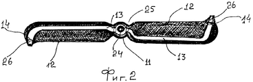
Фиг.2 - лопасти устройства, продольный разрез, вид сверху.Figure 2 - the blades of the device, a longitudinal section, top view.
Фиг.3 - лопасти с вертикальным коллектором.Figure 3 - blades with a vertical manifold.
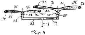
Фиг.4 - лопасти с горизонтальным коллектором.Figure 4 - blades with a horizontal collector.
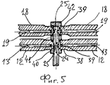
Фиг.5 - узел вертикального коллектора.5 is a node of a vertical collector.
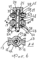
Фиг.6 - узел вертикального коллектора.6 is a node of a vertical collector.
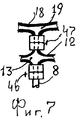
Фиг.7 - лопасти, соединенные друг с другом ступицами.7 - blades connected to each other by hubs.
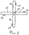
Фиг.8 - лопасти с вертикальным коллектором, вид сверху.Fig - blades with a vertical manifold, top view.
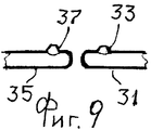
Фиг.9 - часть лопастей с горизонтальным коллектором.Fig.9 - part of the blades with a horizontal manifold.
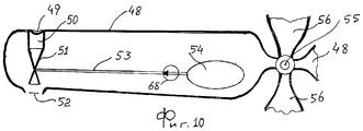
Фиг.10 - пример выполнения реактивных лопастей.Figure 10 is an example of the execution of jet blades.
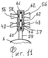
Фиг.11 - пример установки реактивных лопастей.11 is an example of the installation of jet blades.
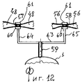
Фиг.12 - пример установки реактивных лопастей.Fig - an example of the installation of jet blades.
Фиг.13 - смесительный узел.Fig - mixing unit.
Вертолет содержит:The helicopter contains:
Корпус 1, хвостовой отвод 2, на конце которого установлены рулевые лопасти 3, к основанию корпуса 1 прикреплены стойки 4 с лыжами на конце. В корпусе 1 установлено нагнетательное устройство 6, например компрессор, кинематически связанное с приводом 7, например двигатель внутреннего сгорания, выход которого патрубком 8 соединен с фланцевым подпятником 9, с которым соединен с возможностью вращения через прокладку 10, фланцевая пята 11. В качестве прокладки 10 может использоваться подшипник. Подпятник 11 соединен с комлями лопастей 12, в которых выполнены сквозные каналы 13, заканчивающиеся в конце этих лопастей со стороны задних кромок приводными отверстиями 14, а начинающиеся в полостях комлевой части этих лопастей. С верхней стороны комлевой части лопастей 12 установлены фланцевая пята 15, которая через прокладку 16 соединена с фланцевым подпятником 17, с возможностью независимого вращения от этой пяты. В качестве прокладки 16 может быть использован подшипник. Подпятник 17 соединен с комлями лопастей 18, в которых выполнены сквозные каналы 19, заканчивающиеся приводными отверстиями 20, выполненными на конце этих лопастей стороны задней кромки. С верхней стороны комлей лопастей 18 установлен фланцевый подпятник 21, соединенный через прокладку 22 с ограничительной пятой 23, с возможностью вращения вокруг ее оси, жестко закрепленной на коллекторе 24, который соединен с патрубком 8 и в котором выполнены отверстия 25 на уровне каналов 13 и 19. Вертикальный коллектор 24 является естественным продолжением патрубка 8, например приварен к нему. Аналогично может быть приварена к нему пята 9, подпятник 11 и пята 15 приварены к лопастям 12, а подпятник 17 и пята 21 приварены к лопастям 18 (Фиг.1, Фиг.2 и Фиг.3).The
Таким образом, лопасти 12 и 18 закреплены на патрубке 8 и вертикальном коллекторе 24 с независимым направлением вращения друг от друга.Thus, the
Образующие приводных отверстий 14 и 20 могут быть выполнены в виде сопел 26 и 27 лопастей 12 и 18 соответственно, сопла 26 и 27 выполнены под углом по отношению к продольным образующим лопастей 12 и 18, оси вращения которых совмещены.The generatrices of the
Патрубок 8 может быть соединен с коллектором 28, по краям которого выполнены отводы 29. На одном из отводов 29 через ступицу 30 установлены лопасти 31 с возможностью вращения вокруг оси ступицы 30, с выполненными в них сквозными каналами 32, заканчивающимися приводными соплами 33. На другом отводе 29 через ступицу 34 установлены лопасти 35 с возможностью вращения вокруг оси ступицы 34, с выполненными в них сквозными каналами 36, заканчивающимися приводными соплами 37. Таким образом, лопасти 31 и 35 установлены на горизонтальном коллекторе 28 параллельно друг другу и с возможностью независимого вращения друг от друга. Сопла 26, 27, 33 и 37 направлены в противоположную сторону направлению вращения лопастей 12, 18, 31 и 35 (Фиг.4).The
Возможен и упрощенный вариант установки лопастей 12 и 18 на вертикальном коллекторе 24, в этом случае лопасти 12 имеют общий комль, выполненный в виде шайбы 38. Аналогичный общий комль, имеющий форму шайбы 39, выполнен из лопастей 18. Эти комли лопастей 12 и 18 зафиксированы, с возможностью вращения вокруг своей оси, при помощи нижней втулки 40 с фиксирующим выступом и закрепленной на патрубке 8, например приваренной к нему, промежуточной втулкой 41 с фиксирующими выступами и верхней втулкой 42 с фиксирующим выступом, закрепленной на коллекторе 24, например при помощи резьбового соединения. Между фиксирующими втулками 40, 41 и 42 и дисками 38 и 39 установлены прокладки 43, например подшипники. Между коллектором 24 и внутренней частью дисков 38 и 39 выполнены полости 45, напрямую связанные со сквозными каналами 13 и 19. Таким образом выполнен единый сквозной канал связывающий выход нагнетательного устройства 6 через патрубок 8, коллектор 24, полости 45 и каналы 13 и 19 с приводными отверстиями 14 и 20, или соплами 33 и 37, которые направлены в противоположную сторону направлению вращения лопастей 12 и 18 (Фиг.5 и Фиг.6).A simplified version of the installation of the
Лопасти 12 и 18 могут быть соединены друг с другом через ступици, лопасть 12 установлена на патрубке 8 через ступицу 46, а лопасть 18 установлена на лопасти 12 через ступицу 47, в этом случае полость патрубка 8 связана с каналами 13 и 19 через полости ступиц 46 и 47 (Фиг.7).The
В целях большей устойчивости сопла 26 лопастей 12 направлены в противоположную относительно направлению сопел 27 лопастей 18, это создает возможность вращаться лопастям 12 в противоположную сторону по отношению к направлению вращения лопастей 18 (Фиг.8).In order to increase the stability of the
В рассмотренных примерах вертолетный винт выполнен из реактивных лопастей, вращающую тягу которым создает воздух высокого давления, выходящий с большой скоростью из сопел 26 и 27.In the examples considered, the helicopter propeller is made of jet blades, the rotating thrust of which is created by high-pressure air exiting at high speed from
Но установка по крайней мере двух пар реактивных лопастей с независимым друг от друга направлением вращения возможно и при применении горелки, создающей реактивную тягу этим лопастям.But the installation of at least two pairs of reactive blades with an independent direction of rotation is possible when using a burner that creates reactive thrust to these blades.
В этом случае в лопаете 48 в передней кромке выполняется воздухозаборное отверстие 49, от которого начинается воздухопровод 50, связанный с эжектирующим устройством 51, например с газожидкостным эжектором, выход которого соединен с соплом 52 горелки и к которому подведен топливопровод 53 от бака 54 для топлива, установленного в комле лопасти 48, аналогичная конструкция и другой лопасти 48, расположенной с противоположной стороны. Над ними может быть установлена другая пара лопастей 56, аналогичных по конструкции лопастям 48, но их сопла горелок направлены в противоположную сторону по отношению к направлению сопел 52 (Фиг.10).In this case, an
Центральные части комлей лопастей 48 и 56 может быть выполнена в виде втулок 57 и 58, которые установлены с возможностью вращения на штоке 59, закрепленном на верхней части корпуса 1 вертолета. Нижняя ограничительная шайба 60, приваренная к штоку 59, и верхняя ограничительная шайба 61, имеющая резьбовое соединение с ним, фиксируют лопасти 48 и 56 от вертикального смещения их втулок 57 и 58, при этом между ними установлены подшипники 62 (Фиг.11).The central parts of the butt of the
Лопасти 48 и 56 могут быть установлены на штоке 59 параллельно друг к другу, это осуществляется при помощи горизонтальной штанги 63, жестко закрепленной на штоке 59, например приваренной к нему, и вертикальных отводов 64 и 65, жестко закрепленных на краях этой штанги 63, например приваренных к ней. На отводах 64 и 65 установлены втулки 57 и 58 соответственно лопастей 48 и 56 с возможностью вращения относительно их оси и зафиксированы на них от вертикального перемещения при помощи ограничительных шайб 60 и 61, нижние из которых приварены к отводам 64 и 65, а верхние имеют с ними резьбовое соединение (Фиг.12).The
Возможно и комплексное решение конструкции реактивного узла, в этом случае в воздухопроводе 50 устанавливается обратный клапан 66, в лопастях 48 и 56 выполняются каналы 13 и 19 для воздуха, соединенные с нагнетательным устройством 6 по схеме, рассмотренной в предыдущих примерах, в этом случае каналы 13 и 19 подключены к воздухопроводам 50 после обратного клапана 66, а на каналах 13 и 19 также установлены обратные клапана 67.A complex solution of the design of the reactive assembly is also possible, in this case a
На топливопроводе 53 может быть установлен насос 68.A
Устройство работает следующим образом.The device operates as follows.
При запуске винта вертолета, состоящего из реактивных лопастей, включается нагнетательное устройство, компрессор, который подает сжатый воздух высокого давления через патрубок 8, распределительный вертикальный коллектор и каналы 13 и 19 к соплам 26 и 27 лопастей 12 и 18, которые под влиянием реактивной силы отдачи воздушной струи, выходящей с большой скоростью из сопел 26 и 27, начинают вращаться, но так как сопло 26 направлено в противоположную сторону по отношению к направлению сопла 27, то пара лопастей 12 будет вращаться в противоположную сторону по отношению к направлению вращения лопастей 18, что улучшает КПД винта вертолета. Аналогично работают и лопасти 31 и 35, на приводные сопла которых подается сжатый воздух от нагнетательного устройства 6 через горизонтальный коллектор. Аналогично работают реактивные лопасти и при применении ступиц 46 и 47, для крепления их на патрубке 8, связи друг с другом и подачи через них сжатого воздуха к приводным соплам этих лопастей, например лопастей 12 и 18.When the helicopter rotor consists of jet blades, the compressor is turned on, a compressor that delivers high pressure compressed air through the
По такому же принципу работают и реактивные пары лопастей 48 и 56, использующие реактивную тягу горелки, в частном случае при установке эжектирующего устройства 51 в реактивные лопасти 48 и 56 при раскручивании их традиционным способом, воздух идущий по воздухопроводу 50 и эжектирующее устройство 51 с большой скоростью засасывает через топливопровод 53 из топливного бака 54 топливо, подавая его на сопло 52, где оно, сгорая, развивает реактивную тягу. Учитывая, что и в данном случае приводные сопла у реактивных лопастей 48 и 56 направлены в противоположные стороны относительно друг друга, то и лопасти 48 и 56 будут вращаться в противоположные стороны относительно друг друга.The reactive pairs of
Комплексное решение, указанное в Фиг.13, позволяет производить запуск реактивных лопастей 48 и 56, создавая эжекцию топлива в эжектирующее устройство 51 за счет подачи на него сжатого воздуха по каналам, соединенным с патрубком 8 ранее рассмотренными способами.The integrated solution indicated in FIG. 13 allows the launch of the
Исполнение реактивных лопастей 12, 31, 48 может считаться обращенным, или зеркальным, по отношению к исполнению реактивных лопастей 18, 35, 56, по форме и направлению приводных сопел, так передние и задние кромки первых выполнены с противоположной стороны по отношению их исполнению у вторых, и приводные сопла у первых направлены в противоположную сторону по отношению к направлению приводных сопел у вторых. Это объясняется необходимостью противоположного направления вращения первых по отношению к направлению вращения вторых.The execution of the
Claims (3)
Priority Applications (1)
| Application Number | Priority Date | Filing Date | Title |
|---|---|---|---|
| RU2000130477/11A RU2271309C2 (en) | 2000-12-06 | 2000-12-06 | Helicopter |
Applications Claiming Priority (1)
| Application Number | Priority Date | Filing Date | Title |
|---|---|---|---|
| RU2000130477/11A RU2271309C2 (en) | 2000-12-06 | 2000-12-06 | Helicopter |
Publications (2)
| Publication Number | Publication Date |
|---|---|
| RU2000130477A RU2000130477A (en) | 2002-11-27 |
| RU2271309C2 true RU2271309C2 (en) | 2006-03-10 |
Family
ID=35833534
Family Applications (1)
| Application Number | Title | Priority Date | Filing Date |
|---|---|---|---|
| RU2000130477/11A RU2271309C2 (en) | 2000-12-06 | 2000-12-06 | Helicopter |
Country Status (1)
| Country | Link |
|---|---|
| RU (1) | RU2271309C2 (en) |
Cited By (5)
| Publication number | Priority date | Publication date | Assignee | Title |
|---|---|---|---|---|
| RU2362707C2 (en) * | 2007-10-29 | 2009-07-27 | Общество с ограниченной ответственностью ООО МУЛЬТИКАР | Jet slot blade (versions) |
| RU2494925C1 (en) * | 2012-04-20 | 2013-10-10 | Михаил Зеликович Боярер | Method of rotorcraft horizontal flight |
| RU2651310C2 (en) * | 2013-03-25 | 2018-04-19 | Айри Ре Срл Униперсонале | Helicopter blades control system using compressed air |
| RU2833362C1 (en) * | 2024-04-27 | 2025-01-20 | Общество с ограниченной ответственностью "Уфа Механика" | Method of operating hybrid power plant of aircraft and plant for implementing method |
| WO2025080155A1 (en) * | 2023-10-09 | 2025-04-17 | Данил Александрович ЛЮКШИН | Power-generating machine |
Citations (4)
| Publication number | Priority date | Publication date | Assignee | Title |
|---|---|---|---|---|
| US3053324A (en) * | 1957-08-07 | 1962-09-11 | Napier & Son Ltd | Gas turbine power units for helicopters |
| US3111992A (en) * | 1960-02-25 | 1963-11-26 | Adolphe C Peterson | Rotor sustentation and propulsion means of jet type |
| US4589611A (en) * | 1983-03-01 | 1986-05-20 | Maurice Ramme | Air jet reaction contrarotating rotor gyrodyne |
| RU2149799C1 (en) * | 1998-07-08 | 2000-05-27 | Малышкин Виктор Михайлович | Combination blade of flying vehicle main rotor and method of flight of flying vehicle |
-
2000
- 2000-12-06 RU RU2000130477/11A patent/RU2271309C2/en not_active IP Right Cessation
Patent Citations (4)
| Publication number | Priority date | Publication date | Assignee | Title |
|---|---|---|---|---|
| US3053324A (en) * | 1957-08-07 | 1962-09-11 | Napier & Son Ltd | Gas turbine power units for helicopters |
| US3111992A (en) * | 1960-02-25 | 1963-11-26 | Adolphe C Peterson | Rotor sustentation and propulsion means of jet type |
| US4589611A (en) * | 1983-03-01 | 1986-05-20 | Maurice Ramme | Air jet reaction contrarotating rotor gyrodyne |
| RU2149799C1 (en) * | 1998-07-08 | 2000-05-27 | Малышкин Виктор Михайлович | Combination blade of flying vehicle main rotor and method of flight of flying vehicle |
Cited By (6)
| Publication number | Priority date | Publication date | Assignee | Title |
|---|---|---|---|---|
| RU2362707C2 (en) * | 2007-10-29 | 2009-07-27 | Общество с ограниченной ответственностью ООО МУЛЬТИКАР | Jet slot blade (versions) |
| RU2494925C1 (en) * | 2012-04-20 | 2013-10-10 | Михаил Зеликович Боярер | Method of rotorcraft horizontal flight |
| RU2651310C2 (en) * | 2013-03-25 | 2018-04-19 | Айри Ре Срл Униперсонале | Helicopter blades control system using compressed air |
| RU2837448C2 (en) * | 2023-10-09 | 2025-03-31 | Данил Александрович Люкшин | Rotor-jet turbine |
| WO2025080155A1 (en) * | 2023-10-09 | 2025-04-17 | Данил Александрович ЛЮКШИН | Power-generating machine |
| RU2833362C1 (en) * | 2024-04-27 | 2025-01-20 | Общество с ограниченной ответственностью "Уфа Механика" | Method of operating hybrid power plant of aircraft and plant for implementing method |
Also Published As
| Publication number | Publication date |
|---|---|
| RU2000130477A (en) | 2002-11-27 |
Similar Documents
| Publication | Publication Date | Title |
|---|---|---|
| US8152934B2 (en) | Aeroengine washing system and method | |
| US12228041B2 (en) | System and method for cleaning a gas turbine engine and related wash stand | |
| NO330072B1 (en) | Method and apparatus for cleaning a turbojet engine | |
| DE60309272T2 (en) | Diffuser with boundary layer injection for a combustion chamber inlet | |
| US8337630B2 (en) | Method for cleaning the compressor of a gas turbine engine | |
| US20140144151A1 (en) | Engine Compressor Wash System | |
| EP2955361B1 (en) | Geared turbofan with improved spinner | |
| US8328513B2 (en) | Systems and apparatus relating to compressor stator blades and diffusers in turbine engines | |
| JP6027245B2 (en) | Fan drive gear system module and inlet guide vane coupling mechanism | |
| US20070217914A1 (en) | Dovetail structure of fan | |
| FR2935349A1 (en) | TURBOMACHINE WITH NON-CARINEATED PROPELLERS | |
| US20180355795A1 (en) | Rotating detonation combustor with fluid diode structure | |
| RU2271309C2 (en) | Helicopter | |
| US7328570B2 (en) | Pulse detonation system for a gas turbine engine having multiple spools | |
| EP3829975B1 (en) | Turbomachine with coaxial propellers | |
| EP3449185B1 (en) | Turbomachine injection system comprising an aerodynamic deflector at its inlet and an air intake swirler | |
| US12152498B2 (en) | Stator aerodynamic components with nozzles and methods for cleaning a turbomachine | |
| CN207470232U (en) | Compressor turbine for aircraft engine | |
| US6250978B1 (en) | Steam phase change waterjet drive | |
| US11441575B2 (en) | Axial compressor | |
| CH270351A (en) | Gas turbine power plant. | |
| WO2025056842A1 (en) | Turbine engine blade assembly | |
| JPH06307289A (en) | Rotary drive device by alame jet | |
| CN108071425A (en) | Axial flow turbine | |
| CN108087040A (en) | Radial-flow turbine |
Legal Events
| Date | Code | Title | Description |
|---|---|---|---|
| FA92 | Acknowledgement of application withdrawn (lack of supplementary materials submitted) |
Effective date: 20050328 |
|
| FZ9A | Application not withdrawn (correction of the notice of withdrawal) |
Effective date: 20050520 |
|
| MM4A | The patent is invalid due to non-payment of fees |
Effective date: 20051207 |