RU2266854C2 - Aerosol can valve assembly with sealing gasket - Google Patents
Aerosol can valve assembly with sealing gasket Download PDFInfo
- Publication number
- RU2266854C2 RU2266854C2 RU2002106417/12A RU2002106417A RU2266854C2 RU 2266854 C2 RU2266854 C2 RU 2266854C2 RU 2002106417/12 A RU2002106417/12 A RU 2002106417/12A RU 2002106417 A RU2002106417 A RU 2002106417A RU 2266854 C2 RU2266854 C2 RU 2266854C2
- Authority
- RU
- Russia
- Prior art keywords
- gasket
- segment
- length
- installation cover
- peripheral
- Prior art date
Links
Images


Classifications
-
- B—PERFORMING OPERATIONS; TRANSPORTING
- B65—CONVEYING; PACKING; STORING; HANDLING THIN OR FILAMENTARY MATERIAL
- B65D—CONTAINERS FOR STORAGE OR TRANSPORT OF ARTICLES OR MATERIALS, e.g. BAGS, BARRELS, BOTTLES, BOXES, CANS, CARTONS, CRATES, DRUMS, JARS, TANKS, HOPPERS, FORWARDING CONTAINERS; ACCESSORIES, CLOSURES, OR FITTINGS THEREFOR; PACKAGING ELEMENTS; PACKAGES
- B65D83/00—Containers or packages with special means for dispensing contents
- B65D83/14—Containers or packages with special means for dispensing contents for delivery of liquid or semi-liquid contents by internal gaseous pressure, i.e. aerosol containers comprising propellant for a product delivered by a propellant
- B65D83/38—Details of the container body
-
- B—PERFORMING OPERATIONS; TRANSPORTING
- B21—MECHANICAL METAL-WORKING WITHOUT ESSENTIALLY REMOVING MATERIAL; PUNCHING METAL
- B21D—WORKING OR PROCESSING OF SHEET METAL OR METAL TUBES, RODS OR PROFILES WITHOUT ESSENTIALLY REMOVING MATERIAL; PUNCHING METAL
- B21D51/00—Making hollow objects
- B21D51/16—Making hollow objects characterised by the use of the objects
- B21D51/38—Making inlet or outlet arrangements of cans, tins, baths, bottles, or other vessels; Making can ends; Making closures
-
- Y—GENERAL TAGGING OF NEW TECHNOLOGICAL DEVELOPMENTS; GENERAL TAGGING OF CROSS-SECTIONAL TECHNOLOGIES SPANNING OVER SEVERAL SECTIONS OF THE IPC; TECHNICAL SUBJECTS COVERED BY FORMER USPC CROSS-REFERENCE ART COLLECTIONS [XRACs] AND DIGESTS
- Y10—TECHNICAL SUBJECTS COVERED BY FORMER USPC
- Y10T—TECHNICAL SUBJECTS COVERED BY FORMER US CLASSIFICATION
- Y10T29/00—Metal working
- Y10T29/49—Method of mechanical manufacture
- Y10T29/49229—Prime mover or fluid pump making
- Y10T29/49297—Seal or packing making
-
- Y—GENERAL TAGGING OF NEW TECHNOLOGICAL DEVELOPMENTS; GENERAL TAGGING OF CROSS-SECTIONAL TECHNOLOGIES SPANNING OVER SEVERAL SECTIONS OF THE IPC; TECHNICAL SUBJECTS COVERED BY FORMER USPC CROSS-REFERENCE ART COLLECTIONS [XRACs] AND DIGESTS
- Y10—TECHNICAL SUBJECTS COVERED BY FORMER USPC
- Y10T—TECHNICAL SUBJECTS COVERED BY FORMER US CLASSIFICATION
- Y10T29/00—Metal working
- Y10T29/49—Method of mechanical manufacture
- Y10T29/49826—Assembling or joining
- Y10T29/49908—Joining by deforming
- Y10T29/49915—Overedge assembling of seated part
- Y10T29/49917—Overedge assembling of seated part by necking in cup or tube wall
- Y10T29/49918—At cup or tube end
-
- Y—GENERAL TAGGING OF NEW TECHNOLOGICAL DEVELOPMENTS; GENERAL TAGGING OF CROSS-SECTIONAL TECHNOLOGIES SPANNING OVER SEVERAL SECTIONS OF THE IPC; TECHNICAL SUBJECTS COVERED BY FORMER USPC CROSS-REFERENCE ART COLLECTIONS [XRACs] AND DIGESTS
- Y10—TECHNICAL SUBJECTS COVERED BY FORMER USPC
- Y10T—TECHNICAL SUBJECTS COVERED BY FORMER US CLASSIFICATION
- Y10T29/00—Metal working
- Y10T29/53—Means to assemble or disassemble
- Y10T29/53443—Means to assemble or disassemble container and fluid component
-
- Y—GENERAL TAGGING OF NEW TECHNOLOGICAL DEVELOPMENTS; GENERAL TAGGING OF CROSS-SECTIONAL TECHNOLOGIES SPANNING OVER SEVERAL SECTIONS OF THE IPC; TECHNICAL SUBJECTS COVERED BY FORMER USPC CROSS-REFERENCE ART COLLECTIONS [XRACs] AND DIGESTS
- Y10—TECHNICAL SUBJECTS COVERED BY FORMER USPC
- Y10T—TECHNICAL SUBJECTS COVERED BY FORMER US CLASSIFICATION
- Y10T29/00—Metal working
- Y10T29/53—Means to assemble or disassemble
- Y10T29/53709—Overedge assembling means
- Y10T29/53717—Annular work
- Y10T29/53726—Annular work with second workpiece inside annular work one workpiece moved to shape the other
- Y10T29/5373—Annular work with second workpiece inside annular work one workpiece moved to shape the other comprising driver for snap-off-mandrel fastener; e.g., Pop [TM] riveter
- Y10T29/53761—Annular work with second workpiece inside annular work one workpiece moved to shape the other comprising driver for snap-off-mandrel fastener; e.g., Pop [TM] riveter having repositionable annulus engaging tool
-
- Y—GENERAL TAGGING OF NEW TECHNOLOGICAL DEVELOPMENTS; GENERAL TAGGING OF CROSS-SECTIONAL TECHNOLOGIES SPANNING OVER SEVERAL SECTIONS OF THE IPC; TECHNICAL SUBJECTS COVERED BY FORMER USPC CROSS-REFERENCE ART COLLECTIONS [XRACs] AND DIGESTS
- Y10—TECHNICAL SUBJECTS COVERED BY FORMER USPC
- Y10T—TECHNICAL SUBJECTS COVERED BY FORMER US CLASSIFICATION
- Y10T29/00—Metal working
- Y10T29/53—Means to assemble or disassemble
- Y10T29/53991—Work gripper, anvil, or element
Abstract
Description
Настоящее изобретение в общем относится к клапанным сборочным узлам для аэрозольных баллонов, при этом сборочные узлы обычно называют "установочными крышками". Более конкретно, настоящее изобретение относится к усовершенствованной прокладке для установочной крышки, т.е. к прокладке, которая создает уплотнение между наружной закраиной установочной крышки и отогнутым краем аэрозольного баллона, при этом манжета сложена вдвое для обеспечения удвоенной толщины прокладочного материала, расположенного внутри канальной части установочной крышки. Изобретение также относится к способу и устройству для образования сложенной прокладки после того, как прокладочный материал размещен на установочной крышке.The present invention generally relates to valve assembly for aerosol cans, with the assembly commonly referred to as “mounting caps”. More specifically, the present invention relates to an improved gasket for a mounting cover, i.e. to the gasket, which creates a seal between the outer rim of the installation cover and the bent edge of the aerosol can, the cuff being folded in half to provide double the thickness of the gasket material located inside the channel portion of the installation cover. The invention also relates to a method and apparatus for forming a folded gasket after the gasket material is placed on the mounting cover.
Аэрозольные баллоны широко используются для упаковки разнообразных текучих материалов, как жидких, так и порошкообразных. Обычно продукт и пропеллент заключаются внутрь баллона под давлением выше атмосферного, а продукт выбрасывается из баллона при открывании вручную распылительного клапана для того, чтобы давление внутри баллона вызвало нагнетание продукта через клапан и соединительные трубки к выпускному отверстию.Aerosol containers are widely used for packaging a variety of fluid materials, both liquid and powder. Typically, the product and the propellant are placed inside the container under atmospheric pressure, and the product is ejected from the container when the spray valve is opened manually so that the pressure inside the container causes the product to be pumped through the valve and connecting pipes to the outlet.
Распылительный клапан, прижатый к установочной крышке, имеющей уплотнительную прокладку, обычно устанавливается в верхнем отверстии баллона, при этом отверстие определено элементом, обычно называемым "отогнутым краем" отверстия баллона. Установочная крышка включает центральную опорную часть для прижатия распылительного клапана, профильную часть, проходящую наружу от опорной части, при этом профильная часть переходит в вытянутую кверху корпусную часть, корпусная часть переходит в канальную часть, заканчивающуюся на юбке, при этом образуется канал для размещения отогнутого края отверстия баллона. Уплотнительная прокладка обычно расположена внутри канальной части, и во многих конфигурациях прокладка продолжается вниз вдоль участка корпусной части. После того как уплотнительная прокладка размещена на установочной крышке, крышка помещается на баллон и прижимается к баллону. Операция прижатия хорошо известна специалистам в области аэрозольных баллонов.A spray valve pressed against a mounting cap having a gasket is typically installed in the upper opening of the cylinder, the opening being defined by an element, commonly referred to as the “bent edge” of the cylinder opening. The mounting cover includes a central support part for pressing the spray valve, a profile part extending outward from the support part, the profile part passing upwardly extending the body part, the body part passing into the channel part ending on the skirt, and a channel is formed for accommodating the bent edge cylinder openings. The seal is typically located within the duct portion, and in many configurations, the seal extends downward along the portion of the cabinet portion. After the gasket is placed on the installation cap, the cap is placed on the cylinder and pressed against the cylinder. The pressing operation is well known to specialists in the field of aerosol containers.
В аэрозольном баллоне является существенным эффективное уплотнение между установочной крышкой и отогнутым краем баллона. Это уплотнение выполнено посредством уплотнительной прокладки, которая должна предотвращать потерю давления (пропеллента) на протяжении границы раздела между отогнутым краем баллона и установочной крышкой.In an aerosol can, effective sealing between the mounting cap and the bent edge of the can is essential. This seal is made by means of a gasket, which should prevent the loss of pressure (propellant) along the interface between the bent edge of the container and the installation cover.
В данной области техники известны уплотнительные прокладки различных типов. Прокладка одного распространенного типа представляет собой обычную плоскую резиновую прокладку, которую помещают внутрь канала установочной крышки. Прокладки этого типа обычно изготавливают экструзией, формованием и вулканизацией компаундированной резиновой смеси с образованием стержней и затем нарезкой или отделением тонких кольцевых секций из полученного экструзией и вулканизированного изделия (трубки). Эти прокладки часто называют отрезными или плоскими прокладками. Отрезные прокладки относительно дороги в изготовлении. Очень трудно контролировать радиальные размеры трубок, из которых изготовлены отрезные прокладки, при этом трубки имеют различные размеры и получаются некруглыми. В результате наружные цилиндрические поверхности этих трубок обычно обрабатываются до нужных размеров, при этом такая обработка значительно увеличивает стоимость производства прокладок.Various types of gaskets are known in the art. The gasket of one common type is a conventional flat rubber gasket that is placed inside the channel of the installation cover. Gaskets of this type are usually made by extrusion, molding and vulcanization of a compound rubber compound to form rods and then cutting or separating thin ring sections from an extruded and vulcanized article (tube). These gaskets are often called detachable or flat gaskets. Cutting gaskets are relatively expensive to manufacture. It is very difficult to control the radial dimensions of the tubes from which the gaskets are made, while the tubes have different sizes and are non-circular. As a result, the outer cylindrical surfaces of these tubes are usually machined to the desired size, and this treatment significantly increases the cost of producing gaskets.
Прокладка другого типа представляет собой относительно тонкую втулку из эластомера, которая устанавливается на корпусной части установочной крышки и затем продвигается по корпусу так, чтобы в конечном счете прокладка находилась на ограниченном участке кольцевого канала установочной крышки, а также проходила вниз вдоль корпусной части за пределы кольцевой зоны прижима. Когда установочная крышка установлена и затем прижата к аэрозольному баллону, уплотнительная прокладка входит в уплотняющее зацепление как с каналом установочной крышки, так и с отогнутым краем баллона. Обычно эти прокладки входят в уплотняющее зацепление с установочной крышкой только на протяжении относительно небольшого кругового участка прокладки в местах, называемых положениями стрелки часов, соответствующими 5 часам и 11 часам. Прокладки этого типа из-за их формы часто называют манжетами.Another type of gasket is a relatively thin elastomer sleeve that is mounted on the housing of the installation cover and then advanced through the housing so that the gasket is ultimately located on a limited portion of the annular channel of the installation cover and also extends downward along the housing outside the annular zone clip. When the installation cap is installed and then pressed against the aerosol can, the gasket is in sealing engagement with both the channel of the installation cap and the bent edge of the cylinder. Typically, these gaskets engage in sealing engagement with the mounting cover only for a relatively small circular portion of the gasket in places called the clock hands corresponding to 5 hours and 11 hours. Gaskets of this type are often called cuffs because of their shape.
Манжеты могут быть получены при продвижения трубки из прокладочного материала в корпус установочной крышки и затем посредством отрезания или отделения кольцевых секций трубки. Осевые высоты манжет существенно больше осевых высот отрезных прокладок. Манжеты обходятся намного дешевле при изготовлении и размещении на установочную крышку, чем отрезные прокладки. При изготовлении манжет нет необходимости обрабатывать наружные цилиндрические поверхности полученных экструзией трубок из прокладочного материала. Кроме того, трубчатую манжету легче разместить на установочной крышке, чем разместить отрезную прокладку на установочной крышке.Cuffs can be obtained by moving the tube from the cushioning material into the body of the mounting cover and then by cutting or separating the annular sections of the tube. The axial heights of the cuffs are substantially greater than the axial heights of the cut-off gaskets. Cuffs are much cheaper to manufacture and place on the installation cover than cut-off gaskets. In the manufacture of cuffs, there is no need to process the outer cylindrical surfaces of the extruded tubes from the cushioning material. In addition, the tubular cuff is easier to place on the installation cover than to place the cut-off gasket on the installation cover.
Уплотнительная прокладка может также быть получена из жидкого материала, содержащего воду или растворитель, который осаждается на кольцевой канал и корпусную часть установочной крышки. Во время затвердевания растворитель или вода испаряется, а оставшийся материал образует упругий уплотнительный материал в канале установочной крышки. Образование прокладки из жидкого материала также является сравнительно дорогостоящей процедурой, требующей выполнения нескольких производственных стадий, включая использование вулканизационных печей или других средств для просушки и отверждения прокладочного материала. Кроме того, необходимо предусмотреть средство для относительного вращения установочной крышки перед дозирующим устройством, которое распыляет точное количество композиции, образующей прокладку. Эти прокладки обычно называют "залитыми внутрь" прокладками. Из-за опасности для окружающей среды "залитые внутрь" прокладки не пользуются успехом.The gasket can also be made from a liquid material containing water or solvent, which is deposited on the annular channel and the body of the installation cover. During solidification, the solvent or water evaporates, and the remaining material forms an elastic sealing material in the channel of the installation cover. The formation of a gasket from a liquid material is also a relatively expensive procedure requiring several production steps, including the use of curing ovens or other means for drying and curing the gasket material. In addition, it is necessary to provide means for relative rotation of the mounting cover in front of the metering device, which sprays the exact amount of the composition forming the gasket. These gaskets are commonly called "in-fill" gaskets. Due to environmental hazards, "embedded" gaskets are not successful.
Следовательно, прокладки описанных выше типов, а также других типов, которые можно использовать, имеют как достоинства, так и недостатки. В основном как отрезные прокладки, так и манжеты обеспечивают хорошее уплотнение. Отрезные прокладки широко используются в отрасли в течение более длительного периода времени, чем манжеты. Когда манжеты используются на оборудовании для заполнения и прижатия, ранее работавшем с плоскими или отрезными прокладками, необходимо затратить время на регулировку прижимного устройства. Часто требуется, чтобы в зависимости от технических требований к затворам снабженных клапанами баллонов, подлежащих прижатию, прижимная линия была приспособлена как к плоским прокладкам, так и к манжетам. Чтобы исключить регулировку прижимного устройства, сопровождающуюся простоем, наблюдается тенденция, особенно в Европе, сохранения плоских или отрезных прокладок, хотя такие прокладки стоят намного дороже.Therefore, gaskets of the types described above, as well as other types that can be used, have both advantages and disadvantages. In general, both cut-off gaskets and cuffs provide good sealing. Cut-off gaskets are widely used in the industry for a longer period of time than cuffs. When cuffs are used on filling and pressing equipment that previously worked with flat or cut-off gaskets, it is necessary to spend time adjusting the pressure device. It is often required that, depending on the technical requirements for the closures of valves equipped with valves to be pressed, the pressure line be adapted to both flat gaskets and cuffs. To exclude the adjustment of the clamping device, accompanied by downtime, there is a tendency, especially in Europe, to maintain flat or cut-off gaskets, although such gaskets are much more expensive.
Ранее была сделана попытка устранить недостатки отрезной прокладки путем преобразования прокладки манжетного типа с точно выдержанными размерами в прокладку отрезного типа. Эта попытка описана в патентной заявке США регистрационный номер 08/384736. Недостаток использования прокладки манжетного/отрезного типа заключается в том, что устройство, используемое для изготовления прокладки манжетного типа рассчитано на обработку трубки, имеющей толщину порядка 0,014 дюйма. Отрезные прокладки обычно имеют толщину 0,040 дюйма, и чтобы изготовить прокладочный материал манжетного типа для преобразования в отрезную прокладку толщиной 0,040 дюйма или больше требуется значительное переоснащение.An earlier attempt was made to eliminate the disadvantages of a cut-off gasket by converting a cuff-type gasket with precisely matched dimensions to a cut-off gasket. This attempt is described in US patent application registration number 08/384736. The disadvantage of using a cuff / cut-off type gasket is that the device used to make the cuff-type gasket is designed to handle a tube having a thickness of about 0.014 inches. Cut-off gaskets typically have a thickness of 0.040 inches, and significant re-equipment is required to produce a cuff-type cushioning material for conversion to a cut-off gasket with a thickness of 0.040 inches or more.
В патентной заявке США регистрационный номер 08/512533 описана уплотненная прокладкой установочная крышка, содержащая прокладку манжетного типа, которая сложена вдвое для образования прокладки, имеющей удвоенную толщину, т.е. толщину, приближающуюся к толщине отрезной прокладки; кроме того, в этой заявке описано, что сегменты сложенной прокладки имеют неравную длину, при этом сегмент, периферический по отношению к наружной поверхности установочной крышки, значительно длиннее, чем сегмент, прилегающий к поверхности установочной крышки. В патентной заявке США регистрационный номер 08/037669 описана уплотненная прокладкой установочная крышка, содержащая сложенную прокладку для установочной крышки, имеющей плоскодонную канальную часть, в которой сегмент прокладки, периферический по отношению к установочной крышке, имеет большую длину, чем сегмент прокладки, прилегающий к установочной крышке; это изменение длины сегментов прокладки сочетается с уменьшением ширины канальной части установочной крышки по сравнению с обычными размерами установочных крышек. Использование установочной крышки с нетрадиционными размерами увеличивает ее стоимость.U.S. Patent Application Serial No. 08/512533 describes a gasket-sealed mounting cap comprising a lip-type gasket that is folded in half to form a gasket having a double thickness, i.e. thickness approaching the thickness of the cutting strip; in addition, this application describes that the segments of the folded gasket are of unequal length, while the segment peripheral to the outer surface of the mounting cover is much longer than the segment adjacent to the surface of the mounting cover. US Patent Application Serial Number 08/037669 describes a gasket-sealed installation cover comprising a folded gasket for a installation cover having a flat-bottomed channel portion in which the gasket segment peripheral to the installation cover is longer than the gasket segment adjacent to the installation cover the lid; this change in the length of the gasket segments is combined with a decrease in the width of the channel portion of the installation cover compared to the usual dimensions of the installation covers. Using an installation cover with non-traditional dimensions increases its cost.
Задача настоящего изобретения заключается в создании уплотненного прокладкой клапанного сборочного узла для аэрозольных баллонов, способа формирования прокладки для установочной крышки и устройства для образования линии складывания в материале прокладки для установочной крышки.An object of the present invention is to provide a gasketed valve assembly for aerosol cans, a method for forming a gasket for a mounting cap, and a device for forming a folding line in the gasket material for the mounting cap.
Другая задача настоящего изобретения заключается в создании установочной крышки для аэрозольного баллона с уплотнительной прокладкой, которая имеет преимущества в отношении стоимости изготовления манжеты и преимущества, обусловленные толщиной отрезной прокладки при осуществлении операции зажатия аэрозольного баллона.Another objective of the present invention is to provide a mounting cap for an aerosol can with a gasket, which has advantages with respect to the cost of manufacturing the cuff and advantages due to the thickness of the cut-off gasket during the operation of clamping the aerosol can.
Используемые здесь выражения "compising" - "содержит", "consisting essentially of" - "состоит в основном из", "consisting of" - "состоит из" определяют разный объем защиты. Выражение "содержит" является самым широким и подразумевает включение других компонентов. Выражение "состоит в основном" является более ограничивающим, поскольку исключает включение какого-либо компонента, который существенно влияет негативным образом на характеристики определенных компонентов. Выражение "состоит из" является самым ограничивающим и ограничивает объем пункта конкретным специально раскрытым компонентом.The expressions used here are “compising” - “contains”, “consisting essentially of” - “consists mainly of”, “consisting of” - “consists of” define a different scope of protection. The expression “contains” is the broadest and implies the inclusion of other components. The expression "consists mainly" is more restrictive, since it excludes the inclusion of any component that significantly affects the characteristics of certain components. The expression “consists of” is the most limiting and limits the scope of the paragraph to a particular, specially disclosed component.
Поставленная задача достигается посредством уплотненного прокладкой сборочного узла для аэрозольного баллона, имеющего отогнутый край, определяющий отверстие в верхней части баллона, который содержит установочную крышку, имеющую центральную опорную часть для прикрепления аэрозольного клапана, профильную часть, проходящую наружу от опоры, корпусную часть, проходящую кверху от внешнего конца профильной части, криволинейную канальную часть для размещения отогнутого края баллона, проходящую наружу от верхнего конца корпусной части и заканчивающуюся на юбке, и прокладку, неподвижно установленную в канальной части и имеющую перекрывающиеся сегменты, при этом один сегмент прилегающий, а другой периферический по отношению к канальной части, причем оба сегмента объединены непрерывной линией складывания, которая является периферической по отношению к корпусной части, при этом сегмент прокладки, периферический по отношению к канальной части, имеет большую длину, чем сегмент, прилегающий по отношению к прокладке, но не длину ее поверхностей, прилегающих по отношению к свободному концу этого периферического сегмента, контактирующего с установочной крышкой при перемещении прокладки в ее крайнее положение в канале.The task is achieved by means of a gasketed assembly for an aerosol can having a bent edge defining an opening in the upper part of the can, which contains a mounting cap having a central support part for attaching the aerosol valve, a profile part extending outward from the support, and the body part extending up from the outer end of the profile portion, a curved channel portion for accommodating the bent edge of the balloon extending outward from the upper end of the body portion and culminating on a skirt and a gasket fixedly installed in the channel part and having overlapping segments, with one segment adjacent and the other peripheral with respect to the channel part, both segments combined by a continuous folding line that is peripheral with respect to the body part, with this segment of the gasket, peripheral with respect to the channel part, has a greater length than the segment adjacent to the gasket, but not the length of its surfaces adjacent to the freedom Nome end of the peripheral segment in contact with the mounting cup when moving pads in its extreme position in the channel.
Настоящее изобретение включает вариант уплотненного прокладкой клапанного сборочного узла для аэрозольного баллона, в котором прокладка содержит полиэтилен сверхнизкой плотности, имеющий добавленный термопластичный эластомер.The present invention includes an embodiment of a gasket-sealed valve assembly for an aerosol can, wherein the gasket contains ultra-low density polyethylene having an added thermoplastic elastomer.
Настоящее изобретение также включает вариант уплотненного прокладкой клапанного сборочного узла для аэрозольного баллона, в котором прокладка состоит в основном из полиэтилена сверхнизкой плотности, имеющего добавленный термопластичный эластомер.The present invention also includes an embodiment of a gasket-sealed valve assembly for an aerosol can, wherein the gasket consists mainly of ultra-low density polyethylene having an added thermoplastic elastomer.
Настоящее изобретение также включает вариант уплотненного прокладкой клапанного сборочного узла для аэрозольного баллона, в котором прокладка состоит из полиэтилена сверхнизкой плотности, имеющего добавленный термопластичный эластомер.The present invention also includes an embodiment of a gasket-sealed valve assembly for an aerosol can, wherein the gasket consists of ultra-low density polyethylene having an added thermoplastic elastomer.
Один из вариантов настоящего изобретения относится к уплотненному прокладкой клапанному сборочному узлу для аэрозольного баллона, имеющего отогнутый край, определяющий центральное отверстие в верхней части баллона, который содержит установочную крышку, имеющую центральную опорную часть для удержания аэрозольного клапана, профильную часть, проходящую наружу от опоры, корпусную часть, проходящую кверху от внешнего конца профильной части, и криволинейную канальную часть для размещения отогнутого края баллона, проходящую наружу от верхнего конца корпусной части и заканчивающуюся на юбке, и прокладку, размещенную на установочной крышке, выполненную вдоль верхнего участка корпусной части и ограниченно проходящую в канальную часть, прилегающую к корпусной части, при этом прокладка имеет перекрывающиеся соприкасающиеся сегменты, объединенные непрерывной линией складывания, расположенной на конце прокладки внутри канальной части, а сегмент прокладки, периферический по отношению к корпусной/канальной части, имеет большую длину, чем другой сегмент, но не длину, при которой свободный конец периферического сегмента в значительной степени соприкасается с поверхностью установочной крышки.One embodiment of the present invention relates to a gasketed valve assembly for an aerosol can having a bent edge defining a central opening in the upper part of the can, which includes a mounting cap having a central support portion for holding the aerosol valve, a profile portion extending outward from the support, a body portion extending upward from the outer end of the profile portion and a curved channel portion for accommodating a bent edge of the balloon extending outward from the top of the end of the body part and ending on the skirt, and a gasket placed on the mounting cover, made along the upper portion of the body part and passing limitedly into the channel part adjacent to the body part, the gasket having overlapping contacting segments united by a continuous folding line located on the end of the gasket inside the channel part, and the gasket segment, peripheral with respect to the body / channel part, has a longer length than the other segment, but not the length at which the free end of the peripheral segment is largely in contact with the surface of the mounting cup.
Поставленная задача достигается также посредством способа формирования прокладки для установочной крышки, имеющей центральную опорную часть для обжимания аэрозольного клапана, профильную часть, проходящую наружу от опорной части, корпусную часть, проходящую кверху от внешнего в радиальном направлении конца профильной части, при этом корпусная часть переходит в канальную часть, которая заканчивается на юбке, канальная часть выполнена с возможностью размещения отогнутого края аэрозольного баллона для зажатия в ней, включающего следующие этапы:The task is also achieved by a method of forming a gasket for an installation cover having a central support part for compressing the aerosol valve, a profile part extending outward from the support part, a body part extending upward from the radially outer end of the profile part, while the body part goes into the channel part that ends on the skirt, the channel part is arranged to accommodate the bent edge of the aerosol can for clamping in it, including the following General steps:
a) расположение трубки прокладочного материала вдоль корпусной части установочной крышки,a) the location of the cushioning tube along the body of the installation cover,
b) продвижение трубки прокладочного материала в канальную часть установочной крышки, образование непрерывной линии складывания в прокладочном материале, и создание сегмента прокладочного материала по каждую сторону от линии складывания,b) moving the cushioning material tube into the channel portion of the mounting lid, forming a continuous folding line in the cushioning material, and creating a segment of cushioning material on each side of the folding line,
c) наложение одного сегмента прокладки на другой сегмент, чтобы образовать сложенную прокладку, имеющую перекрывающиеся свободные края, иc) overlaying one gasket segment on another segment to form a folded gasket having overlapping free edges, and
d) расположение сложенной прокладки вдоль верхнего участка корпусной части и перемещение на ограниченное расстояние в канальную часть, при этом сложенную прокладку располагают так, чтобы перекрывающиеся свободные края прокладки были на периферии по отношению к канальной части. Поставленная задача также достигается посредством устройства для образования линии складывания в материале прокладки для аэрозольной установочной крышки, которое содержит:d) positioning the folded gasket along the upper portion of the body portion and moving a limited distance to the channel portion, wherein the folded gasket is positioned so that the overlapping free edges of the gasket are at the periphery with respect to the channel portion. The task is also achieved by means of a device for forming a folding line in the gasket material for the aerosol installation cover, which contains:
a) пробойник, закрепленный на ползуне с возвратно-поступательным движением, имеющий центральное отверстие для размещения корпуса установочной крышки и твердую переднюю часть, выполненную с возможностью прохождения в канальную часть установочной крышки,a) a punch mounted on a slide with a reciprocating movement, having a Central hole to accommodate the housing of the installation cover and a solid front part made with the possibility of passage into the channel part of the installation cover,
b) при этом передняя часть имеет сужающуюся книзу и внутрь наружную поверхность и заканчивается кольцевым наружным закруглением, иb) wherein the front part has an outer surface tapering downward and inward and ends with an outer ring rounding, and
с) ступеньку или заплечик во внутреннем диаметре пробойника, направленный внутрь передней части и выполненный с возможностью проталкивания прокладочного материала, расположенного на корпусной части установочной крышки, в канальную часть установочной крышки, где наружная кромка образует линию складывания.c) a step or a shoulder in the inner diameter of the punch, directed inward to the front and configured to push the cushioning material located on the body of the installation cover into the channel part of the installation cover, where the outer edge forms a folding line.
В самом широком аспекте уплотненная прокладкой установочная крышка как изделие производства согласно настоящему изобретению представляет собой установочную крышку, имеющую криволинейную канальную часть, в которой расположена прокладка манжетного типа, имеющая несколько сегментов разной длины, наложенных друг на друга, при этом сегменты объединены по непрерывной линии складывания и расположены так, что, когда прокладка окончательно зажата в нужном месте в канальной части установочной крышки, линия складывания находится по радиусу снаружи относительно участка прокладки, прилегающего к корпусу установочной крышки, а длина сегмента сложенной прокладки, периферического по отношению к канальной части установочной крышки, больше длины другого сегмента, однако более длинный сегмент не должен иметь какого-либо значительного участка, а предпочтительно не должен иметь участка, соприкасающегося с установочной крышкой во время установки в нужное положение в канальной части установочной крышки. Если длина сегмента прокладки, периферического по отношению к установочной крышке, такая, что его участок прилегает или находится на корпусной части установочной крышки, то возникает возможность защемления прокладки по отношению к корпусной части между корпусной частью и отогнутым краем баллона при попытке посредством отогнутого края продвинуть сложенную прокладку вдоль корпуса и в канал установочной крышки с достижением результата, заключающегося в том, что сложенная прокладка не будет продвинута в канал к нужному месту и, следовательно, будет получена дефектная уплотненная прокладкой установочная крышка. Эта проблема особенно проявляется в случае установочных крышек, имеющих криволинейную канальную часть.In the broadest aspect, the gasket-sealed installation cover as an article of manufacture according to the present invention is an installation cover having a curved channel portion in which a cuff-type gasket is located, having several segments of different lengths superimposed on one another, the segments being combined along a continuous folding line and located so that when the gasket is finally clamped in the right place in the channel part of the installation cover, the folding line is located along the radius of arms relative to the gasket portion adjacent to the body of the installation cover, and the length of the segment of the folded gasket, peripheral to the channel portion of the installation cover, is greater than the length of the other segment, however, the longer segment should not have any significant section, and preferably should not have a section in contact with the installation cover during installation in the desired position in the channel part of the installation cover. If the length of the gasket segment, peripheral with respect to the installation cover, is such that its portion is adjacent or located on the body of the installation cover, then it becomes possible to pinch the gasket in relation to the body between the body and the bent edge of the container when trying to advance the folded edge laying along the body and into the channel of the installation cover with the achievement of the result that the folded gasket will not advance into the channel to the desired place and, consequently no, it would have received a defective Packing mounting cup. This problem is especially apparent in the case of mounting covers having a curved channel portion.
Толщина индивидуальных сегментов прокладки должна учитываться при определении допустимого процентного увеличения длины самого длинного сегмента. Чем больше толщина каждого сегмента сложенной прокладки, тем больше допустимое процентное увеличение длины более длинного сегмента прокладки по сравнению с более коротким сегментом. Это происходит по той причине, что при более коротком сегменте большей толщины возрастает расстояние более длинного сегмента от поверхности корпусной части.The thickness of the individual gasket segments should be considered when determining the allowable percentage increase in the length of the longest segment. The greater the thickness of each segment of the folded gasket, the greater the permissible percentage increase in the length of a longer gasket segment compared to a shorter segment. This is due to the fact that with a shorter segment of greater thickness, the distance of the longer segment from the surface of the body part increases.
В случае предпочтительной формы прокладки толщина втулки прокладки составляет 0,022 дюйма, а длина сегмента прокладки, периферического по отношению к установочной крышке, должна быть не больше 125% длины сегмента прокладки, прилегающего к установочной крышке.In the case of a preferred gasket shape, the thickness of the gasket sleeve is 0.022 inches, and the length of the gasket segment peripheral to the installation cover should be no more than 125% of the length of the gasket segment adjacent to the installation cover.
В случае еще более предпочтительной формы установочной крышки сложенная манжета выполнена из полиэтилена сверхнизкой плотности с добавленным термопластичным эластомером.In the case of an even more preferred form of the mounting cover, the folded cuff is made of ultra-low density polyethylene with added thermoplastic elastomer.
В самом широком аспекте способа этого изобретения прокладку образуют путем продвижения прокладочного материала в виде втулки вдоль корпусной части и в канальную часть установочной крышки, и при этом продвигают инструмент, который создает кольцевую линию сжимающей силы по отношению к прокладке и тем самым образует в прокладке непрерывную линию складывания с получением результата, заключающегося в том, что участок прокладки, периферический по отношению к корпусной части установочной крышки, оказывается наложенным на другой участок прокладочного материала, при этом продвигаемый инструмент, который образует непрерывную линию складывания в прокладке, ударяет по определенному месту на всем протяжении длины манжеты, чтобы образовать сложенные сегменты прокладки, имеющие необходимые относительные длины.In the broadest aspect of the method of this invention, the gasket is formed by advancing the gasket material in the form of a sleeve along the body portion and into the channel portion of the mounting cover, and while promoting the tool, which creates a ring line of compressive force with respect to the gasket and thereby forms a continuous line in the gasket folding to obtain the result that the gasket portion peripheral with respect to the body part of the installation cover is superimposed on another ladochnogo material thus propelled tool that forms the continuous fold line in the gasket strikes at a specific place throughout the length of the cuff to form the folded segments of the gasket having the desired relative lengths.
Устройство согласно изобретению содержит пробойник, который закреплен с возможностью совершения возвратно-поступательного движения; пробойник продвигает манжету в канальную часть, где он оказывается выдвинутым напротив прокладки. Рабочая часть пробойника имеет направленную книзу и кверху конусность наружной поверхности, а также плоские зубцы на наружной поверхности, которые уменьшают площадь соприкосновения сложенной прокладки и наружной поверхности пробойника и тем самым предотвращают удаление сложенной прокладки из установочной крышки во время извлечения пробойника. Более подробно пробойник рассмотрен ниже.The device according to the invention contains a punch, which is fixed with the possibility of reciprocating motion; the punch advances the cuff into the duct portion, where it is extended opposite the gasket. The working part of the punch has a taper of the outer surface directed downward and upward, as well as flat teeth on the outer surface, which reduce the contact area of the folded gasket and the outer surface of the piercer and thereby prevent the folded gasket from being removed from the installation cover during the extraction of the piercer. The punch is described in more detail below.
В способе образования уплотненной прокладкой установочной крышки вслед за наложением внешнего участка прокладки на внутренний участок в месте, где прокладка частично находится в канале, прокладку продвигают дальше в канальную часть установочной крышки. В установочной крышке, в которой канальная часть установочной крышки выполнена криволинейной формы, прокладку первоначально размещают вертикально вдоль корпусной части установочной крышки и немного вводят в канальную часть, прилегающую к корпусной части крышки, при этом свободные края прокладки прилегают к корпусной части установочной крышки. Введением отогнутого края баллона в канальную часть продвигают прокладку в канальную часть до согласования с криволинейной формой канальной части установочной крышки.In the method of forming the installation cover with a sealed gasket following the application of the external gasket portion to the internal portion at a place where the gasket is partially located in the channel, the gasket is advanced further into the channel portion of the installation cover. In the installation cover, in which the channel part of the installation cover is made in a curved shape, the gasket is initially placed vertically along the body of the installation cover and slightly inserted into the channel part adjacent to the body part of the cover, while the free edges of the gasket are adjacent to the body of the installation cover. By introducing the bent edge of the cylinder into the channel part, the gasket is advanced into the channel part until it matches the curved shape of the channel part of the installation cover.
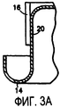
Чтобы расположить манжету на установочной крышке до образования сложенной прокладки, манжету первоначально размещают на корпусной части установочной крышки. Затем манжету отрезают от полученной экструзией трубки прокладочного материала. После отрезания манжету немного продвигают вдоль корпусной части установочной крышки и затем продвигают дальше в кольцевой канал в течение двух отдельных этапов, при этом сжимающая сила, действующая на манжету, приводит к образованию нескольких сегментов манжеты, наложенных друг на друга. Устройство и способ осуществления этапов, показанных на фигурах 3А и 3В настоящего изобретения, описаны в патентной заявке США регистрационный номер 08/512533, поданной 8 августа 1995 г., раскрытие которой включено в настоящую заявку посредством ссылки.In order to position the cuff on the mounting cover until a folded gasket is formed, the cuff is initially placed on the body of the mounting cover. Then the cuff is cut from the extrusion tube of the cushioning material. After cutting, the cuff is slightly advanced along the body of the mounting cover and then further advanced into the annular channel in two separate steps, while the compressive force acting on the cuff leads to the formation of several cuff segments superimposed on each other. The apparatus and method for carrying out the steps shown in FIGS. 3A and 3B of the present invention are described in US Patent Application Serial Number 08/512533, filed August 8, 1995, the disclosure of which is incorporated herein by reference.
Было сделано несколько попыток имитировать отрезные прокладки для аэрозольной установочной крышки путем создания сложенной манжеты. В случае установочных крышек, имеющих криволинейную канальную часть, особенно, когда баллон выполнен из алюминия, и существует известная в отрасли проблема видимых зазоров в отогнутом конце, эти попытки привели к получению неудовлетворительных результатов вследствие расположения прокладки, не соответствующего ее окончательному положению из-за характеристик сжимаемости материала прокладки и различия в относительных длинах сегментов сложенной прокладки. Было обнаружено, что в случае каналов криволинейной формы излишне длинный внешний сегмент прокладки может соприкасаться с прилегающей корпусной частью установочной крышки на длине, достаточной для зажатия между наружной стенкой корпуса установочной крышки и отогнутым краем баллона, в результате чего исключается необходимое продвижение прокладки до требуемого места в канале. Эта проблема характерна для криволинейных каналов.Several attempts have been made to simulate detachable gaskets for an aerosol mounting cap by creating a folded cuff. In the case of mounting caps having a curved channel portion, especially when the container is made of aluminum and there is a known industry problem of visible clearances at the bent end, these attempts have led to unsatisfactory results due to the location of the gasket that does not correspond to its final position due to characteristics the compressibility of the gasket material and differences in the relative lengths of the segments of the folded gasket. It was found that in the case of channels of a curvilinear shape, an excessively long external gasket segment can come into contact with the adjacent body of the installation cover for a length sufficient to be clamped between the external wall of the installation cover body and the bent edge of the cylinder, as a result of which the necessary advancement of the gasket to the desired place in channel. This problem is typical for curved channels.
Дополнительные выгоды и преимущества изобретения станут очевидными из рассмотрения нижеследующего подробного описания, сделанного со ссылками на сопровождающие чертежи, которые точно определяют и иллюстрируют предпочтительный вариант осуществления изобретения.Additional benefits and advantages of the invention will become apparent from a consideration of the following detailed description made with reference to the accompanying drawings, which accurately define and illustrate a preferred embodiment of the invention.
На чертежах:In the drawings:
на фиг.1 показано перспективное изображение уплотненной прокладкой установочной крышки настоящего изобретения, прижатой к отверстию в аэрозольном баллоне;figure 1 shows a perspective image of a sealed gasket installation cover of the present invention, pressed against a hole in an aerosol can;
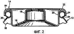
на фиг.2 показан разрез уплотненной прокладкой установочной крышки настоящего изобретения и местный разрез аэрозольного баллона по линии 2-2 на фиг.1;figure 2 shows a section of a sealed gasket installation cover of the present invention and a local section of an aerosol can along line 2-2 in figure 1;
на фиг.3A-3F показаны частичные изображения, иллюстрирующие последовательность этапов при преобразовании первоначально размещенной манжеты на установочной крышке в течение процесса прижатия уплотненной прокладкой установочной крышки к аэрозольному баллону;3A-3F are partial views illustrating a sequence of steps when converting an initially placed cuff on a mounting cap during the process of pressing the sealing gasket on the mounting cap against an aerosol can;
на фиг.4 показан разрез пробойника для образования линии складывания на прокладке; иfigure 4 shows a section of a punch to form a folding line on the gasket; and
на фиг.5 показано увеличенное частичное изображение наружной поверхности пробойника на фиг.4.figure 5 shows an enlarged partial image of the outer surface of the punch in figure 4.
На фиг.1 и 2 показан клапанный сборочный узел, в целом обозначенный позицией 10, расположенный внутри открытого конца 32 баллона 12. Точнее говоря, клапанный узел 10 (клапанный элемент не показан) включает установочную крышку, в целом обозначенную позицией 14, и сложенную прокладку 64. В свою очередь, установочная крышка содержит опорную часть 18, профильную часть 19 и корпусную часть 20, заканчивающуюся на направленной по радиусу наружу канальной части 22, в которой размещена прокладка 64, при этом канальная часть 22 заканчивается на юбке 24. Баллон 12 имеет верхнюю часть 30, которая образует центральное отверстие 32 баллона, и верхний свернутый обод или отогнутый край 34, который проходит вокруг отверстия 32. Как показано на фиг.2, канал 22 крышки 14 расположен на отогнутом крае 34, а отогнутый край размещен в нем. Сложенная прокладка 64 находится между отогнутым краем 34 и под поверхностью канала 22. Отогнутый край 34 непосредственно поддерживает клапанный сборочный узел 10.Figures 1 and 2 show a valve assembly, generally indicated by 10, located inside the
Кроме того, на фиг.2 видно, что для постоянного соединения узла 10 с баллоном 12 участок корпуса 20, находящийся ниже опорного края 34, прижат в радиальном направлении наружу по окружности корпуса 20, в результате чего сборочный узел 10 прижат к баллону 12. Эта операция прижатия также обеспечивает плотную прессовую посадку прокладки 64 по отношению как к отогнутому краю 34, так и нижней поверхности канала 22, тем самым образуя между ними эффективное уплотнение. Операция прижатия хорошо известна специалистам в данной области техники.In addition, FIG. 2 shows that for the permanent connection of the assembly 10 with the
Конфигурацию прокладки и расположение ее на установочной крышке осуществляют путем выполнения ряда этапов, начиная с размещения отрезка трубчатого прокладочного материала на корпусной части уже образованной установочной крышки. Процесс начального размещения трубчатой прокладки или манжеты на корпусной части установочной крышки и ее частичного продвижения, а также устройство для осуществления этих этапов описано в патенте США №4546525, опубликованном 15 октября 1985 г.; описание этого патента США включено в настоящую заявку посредством ссылки.The configuration of the gasket and its location on the installation cover is carried out by performing a number of steps, starting with placing a piece of tubular gasket material on the body of the already formed installation cover. The process of initial placement of a tubular gasket or cuff on the body of the installation cover and its partial promotion, as well as a device for performing these steps are described in US patent No. 4546525, published October 15, 1985; the description of this US patent is incorporated into this application by reference.
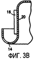
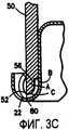
На фиг.3А показана манжета 16, размещенная на корпусной части 20 установочной крышки 14 после того, как манжета была отрезана от трубчатого рулона прокладки. На фиг.3В манжета 16 показана частично продвинутой по корпусной части установочной крышки. Как показано на фиг.3С, затем манжету продвигают дальше по корпусной части 22 и вводят в канальную часть посредством пробойника 50, имеющего относительно острую переднюю часть. Детали конструкции пробойника описываются ниже. Когда относительно острая передняя часть пробойника, находящаяся против прокладки в канале установочной крышки, достигает нижней точки, то при наличии опорного элемента в основании установочной крышки, оказывающего сопротивление действию пробойника, в манжете образуется линия 80 складывания, что приводит к наложению части прокладки, проходящей снаружи относительно линии складывания, на часть прокладки, проходящую внутри на корпусной части установочной крышки; посредством этого образуется сдвоенная сегментная прокладка, имеющая удвоенную толщину.On figa shows the
На фиг.3В-3Р показаны последовательные положения сложенной манжеты при продвижении отогнутого края баллона против прокладки в конечное положение на фиг.3Г, где установочная крышка прижата к баллону.On figv-3P shows the sequential position of the folded cuff while advancing the bent edge of the cylinder against the gasket in the final position on figg, where the installation cap is pressed against the cylinder.
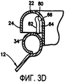
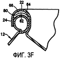
На фиг.3D отогнутый край 34 баллона продвинут к внешнему сегменту 62 сложенной прокладки 64, при этом прокладка 64 также имеет внутренний сегмент 66. На фиг.3Е и 3F представлены те же элементы, что и на фиг.3D.In FIG. 3D, the
Что касается предельного положения сложенной прокладки в канальной части установочной крышки, то оно имеет большое значение, особенно в случае, когда установочную крышку/аэрозольный баллон необходимо заполнить под давлением, т.е. когда пропеллент вводят в баллон при удалении вакуума из баллона через пространство между установочной крышкой и отогнутым краем баллона, потому что сложенная прокладка не должна выходить за пределы концевого края юбки установочной крышки.As for the limit position of the folded gasket in the channel part of the installation cover, it is of great importance, especially in the case when the installation cover / aerosol can must be filled under pressure, i.e. when the propellant is introduced into the container while removing the vacuum from the container through the space between the installation cover and the bent edge of the container, because the folded gasket must not extend beyond the end edge of the installation cover skirt.
Чтобы образовать сложенную прокладку, линию складывания необходимо расположить на всем протяжении длины манжеты таким образом, чтобы значительная часть внешнего сегмента (сегмента, периферического по отношению к установочной крышке), накладываемого на сегмент, прилегающий к корпусной части установочной крышки, существенно не соприкасалась с корпусной частью установочной крышки во время этапов продвижения сложенной прокладки вдоль корпуса и в канал до ее конечного расположения внутри канальной части установочной крышки. Предпочтительно, внешний сегмент сложенной прокладки имеет длину не больше 125% длины внутреннего сегмента. Создание сегментированной прокладки, в которой внешний сегмент длиннее внутреннего сегмента, гарантирует, что отогнутый край баллона будет первым соприкасаться с внешним сегментом, а вся прокладка будет проталкиваться вперед вдоль корпуса установочной крышки и в канал. Когда длина внешнего сегмента существенно меньше длины внутреннего сегмента, существует благоприятная возможность для раскладывания сложенной сегментированной прокладки, при этом внешний сегмент выходит из перекрытия по отношению к внутреннему сегменту прокладки. Однако длина внешнего сегмента не должна быть настолько больше длины внутреннего сегмента, когда значительная часть внешнего сегмента соприкасается с корпусом установочной крышки. Значительная часть избыточного внешнего сегмента проявляется в том, что излишняя длина дает возможность защемления внешнего сегмента между отогнутым краем баллона и корпусом установочной крышки и, следовательно, исключает правильное введение сложенной прокладки в канальную часть установочной крышки. Предпочтительно, внешний сегмент не должен соприкасаться с корпусом установочной крышки.To form a folded gasket, the folding line must be positioned along the entire length of the cuff so that a significant part of the outer segment (segment peripheral to the mounting cover) superimposed on the segment adjacent to the body part of the mounting cover does not substantially come into contact with the body part the installation cover during the steps of advancing the folded gasket along the housing and into the channel to its final location inside the channel portion of the installation cover. Preferably, the outer segment of the folded gasket has a length of not more than 125% of the length of the inner segment. The creation of a segmented gasket, in which the outer segment is longer than the inner segment, ensures that the bent edge of the cylinder will first come into contact with the outer segment, and the entire gasket will be pushed forward along the body of the installation cover and into the channel. When the length of the outer segment is significantly less than the length of the inner segment, there is a favorable opportunity for folding the folded segmented gasket, while the outer segment comes out of overlap with respect to the inner segment of the gasket. However, the length of the outer segment should not be so much longer than the length of the inner segment when a significant part of the outer segment is in contact with the housing of the installation cover. A significant part of the excess outer segment is manifested in the fact that the excess length makes it possible to pinch the outer segment between the bent edge of the container and the body of the installation cover and, therefore, eliminates the correct introduction of the folded gasket into the channel part of the installation cover. Preferably, the outer segment should not be in contact with the housing of the installation cover.
Как отмечено выше, является критичным, чтобы сегмент прокладки, проходящий от линии складывания к концу прокладки, периферическому по отношению к корпусной части установочной крышки, был наложен на сегмент прокладки установочной крышки, который проходит от линии складывания до конца прокладки, прилегающего к корпусной части крышки. При таком складывании, т.е. при наличии линии складывания, периферической по отношению к корпусной части, любое отклонение от удовлетворительного прижима установочной крышки и отогнутого края баллона, которое обычно создает путь утечки для пропеллента, исключается, как показано на фиг.3Е, путем прижатия одного сегмента прокладки к внутренней стороне канальной части установочной крышки и другого сегмента прокладки к отогнутому краю баллона с захватом утекающего пропеллента в складке между слоями прокладки. Если линию складывания слоистой прокладки перевернуть, т.е. сделать линию складывания прилегающей к корпусу установочной крышки, слабый прижим приведет к тому, что пропеллент будет обходить прокладку и выходить либо между прокладкой и установочной крышкой, либо между прокладкой и отогнутым краем баллона, либо по обоим путям.As noted above, it is critical that the gasket segment extending from the folding line to the end of the gasket peripheral to the body of the installation cover is superimposed on the gasket segment of the installation cover, which extends from the folding line to the end of the gasket adjacent to the body of the cover . With this folding, i.e. in the presence of a folding line peripheral to the body part, any deviation from the satisfactory clamping of the mounting cap and the bent edge of the cylinder, which usually creates a creepage path for the propellant, is eliminated, as shown in FIG. 3E, by pressing one segment of the gasket to the inside of the duct part of the installation cover and another segment of the gasket to the bent edge of the cylinder with the capture of the leaky propellant in the crease between the layers of the gasket. If the folding line of the layered strip is turned over, i.e. make the folding line adjacent to the body of the installation cover, a weak clamp will cause the propellant to bypass the gasket and exit either between the gasket and the installation cover, or between the gasket and the bent edge of the cylinder, or both ways.
Этап на фиг.3С осуществляют при установке пробойника 50 (см. фиг.3С), имеющего непрерывную кромку 52 (см. фиг.4), на соответствующий ползун с возвратно-поступательным движением (непоказанный). Было обнаружено, что при осуществлении этапа на фиг.3С является достаточным размещение перевернутой установочной крышки на фиг.3В на верхней части поверхности поршня (непоказанного), который перемещается внутри четырехдюймового цилиндра. В цилиндр нагнетают рабочую жидкость до давления 20 фунтов на квадратный дюйм, чтобы создать дополнительную силу сопротивления продвижению пробойника, составляющую 250 фунтов.The step in FIG. 3C is carried out by installing a punch 50 (see FIG. 3C) having a continuous edge 52 (see FIG. 4) on a corresponding slider with reciprocating motion (not shown). It has been found that during the implementation of the step in FIG. 3C, it is sufficient to place the inverted mounting cover in FIG. 3B on the upper surface of the piston (not shown) that moves inside the four-inch cylinder. Hydraulic fluid is injected into the cylinder to a pressure of 20 psi to create an additional resistance force of 250 pounds to advance the punch.
В предпочтительном варианте выполнения сложенной прокладки радиальная толщина материала манжеты, такой, какая показана на фиг.3А, составляет 0,022 дюйма. Когда сегменты прокладки уложены друг на друга, суммарная толщина прокладки составляет 0,044 дюйма. Установлено, что сложенная прокладка, имеющая внешний сегмент 62 длиной 0,114 дюйма и внутренний сегмент 66 длиной 0,103 дюйма, обеспечивает удовлетворительное уплотнение алюминиевых установочных крышек, имеющих криволинейную канальную часть. Вероятно, суммарную толщину прокладки можно изменять от приблизительно 0,038 дюйма до 0,050 дюйма.In a preferred embodiment of the folded gasket, the radial thickness of the cuff material, such as that shown in FIG. 3A, is 0.022 inches. When the gasket segments are stacked on top of each other, the total thickness of the gasket is 0.044 inches. It has been found that a folded gasket having an
На фиг.4-5 показаны конструктивные детали пробойника, используемого для осуществления этапа 3С способа настоящего изобретения.Figures 4-5 show structural details of a punch used to carry out step 3C of the method of the present invention.
На фиг.4 пробойник, в целом обозначенный как 50, имеет переднюю кромку 52. Выше кромки 52 находится направленная по радиусу внутрь пробойника ступенька или заплечик 56, который, как показано на фиг.3С, входит в соприкосновение с прокладочным материалом для продвижения прокладочного материала по корпусной и канальной частям установочной крышки в положение, показанное на фиг.3С, соответственно нижняя часть пробойника будет находиться против прокладочного материала и образовывать кольцевую зону соприкосновения с непрерывной линией складывания, что при извлечении пробойника позволяет сегменту прокладочного материала, отстоящего в радиальном направлении на расстояние от места изгиба, по существу уложиться поверх сегмента материала прокладки, прилегающего к корпусной части установочной крышки.In FIG. 4, the punch, generally designated 50, has a
Было установлено, что пробойник, имеющий следующие размеры, является подходящим для создания предпочтительной сложенной прокладки настоящего изобретения, имеющей внешний и внутренний сегменты сложенной прокладки, составляющие 0,114 дюйма и 0,103 дюйма соответственно:It has been found that a punch having the following dimensions is suitable for creating a preferred folded gasket of the present invention having external and internal segments of the folded gasket constituting 0.114 inches and 0.103 inches, respectively:
1) "А" (см. фиг.3С) представляет собой нижнюю или рабочую часть пробойника, при этом наружная кольцевая поверхность этой рабочей части пробойника наклонена под углом 5° книзу и внутрь, начиная от точки, находящейся на 0,375 дюйма выше нижней кромки пробойника; наружный диаметр пробойника у верхней границы конусности составляет 1,150 дюйма, а соответствующий диаметр у нижнего или переднего конца конусности составляет 1,108 дюйма.1) “A” (see FIG. 3C) represents the bottom or working part of the punch, with the outer annular surface of this working part of the punch being tilted at an angle of 5 ° downward and inward, starting from a point 0.375 inches above the bottom edge of the punch ; the outer diameter of the piercer at the top of the taper is 1.150 inches, and the corresponding diameter at the lower or front end of the taper is 1.108 inches.
2) "В" представляет собой ступеньку или заплечик в пробойнике, а вертикальная стенка, находящаяся ниже ступеньки или заплечика, имеет диаметр 1,047 дюйма, при этом осевое расстояние между заплечиком и передней частью пробойника составляет 0,075 дюйма.2) “B” is a step or shoulder in the punch, and the vertical wall below the step or shoulder has a diameter of 1.047 inches, with an axial distance between the shoulder and the front of the punch of 0.075 inches.
3) Радиус "С" передней части составляет 0,040 дюйма.3) The radius "C" of the front is 0.040 inches.
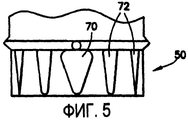
Такой пробойник используют для образования сложенной прокладки в случае установочной крышки, имеющей корпусную часть с наружным диаметром 0,989 дюйма, при этом внутренний диаметр пробойника выше заплечика "В" составляет 0,994 дюйма. Для обеспечения удаления пробойника из сложенной прокладки наружная поверхность нижней части пробойника имеет, как показано на фиг.5, ряд плоских зубцов, полученных путем создания вырезов в поверхности. Имеются четыре плоских зубца 70, расположенных с разнесением на 90° вокруг периферийной наружной поверхности пробойника, и восемь небольших плоских зубцов 72, по два между каждыми соседними большими плоскими зубцами 70, расположенных с разнесением на 30°. Периферийные плоские зубцы обеспечивают открытые пространства между внешним сегментом сложенной прокладки и поверхностью пробойника, уменьшая любое прилипание сложенной прокладки к пробойнику и удаления ее из установочной крышки при извлечении пробойника, образующего линию складывания. Большие плоские зубцы обеспечивают возможность прохождения пальцев съемника пробойника (непоказанных) между внешним сегментом прокладки и нижней наружной поверхностью пробойника, дополнительно обеспечивая сохранение позиционной целостности сложенной прокладки в установочной крышке.Such a punch is used to form a folded gasket in the case of a mounting cover having a body portion with an outer diameter of 0.989 inches, with an internal diameter of the punch above shoulder "B" of 0.994 inches. To ensure removal of the punch from the folded gasket, the outer surface of the lower part of the punch has, as shown in FIG. 5, a series of flat teeth obtained by creating cuts in the surface. There are four
После образования линии складывания в прокладке и удаления пробойника линии складывания прокладку подвергают воздействию продвигающей оправки, имеющей нижнюю переднюю кромку, которая соприкасается со сложенной прокладкой, при этом передняя кромка выполнена сужающейся кверху и книзу, и эту оправку продвигают вдоль корпуса установочной крышки на заранее определенное расстояние с тем, чтобы расположить или повторно расположить сложенную прокладку в требуемом месте, показанном на фиг.3D. Было показано, что оправка, имеющая нижнюю поверхность с конусностью 25°, является приемлемой для этого этапа.After the folding line is formed in the gasket and the punch of the folding line is removed, the gasket is exposed to an advance mandrel having a lower front edge that is in contact with the folded gasket, the front edge being tapering up and down, and this mandrel is advanced along the mounting cover body for a predetermined distance in order to position or re-position the folded gasket in the desired location shown in fig.3D. It has been shown that a mandrel having a bottom surface with a taper of 25 ° is acceptable for this step.
Установочные крышки описанного выше вида хорошо известны в данной области техники, и крышки можно изготавливать любым подходящим способом и из любого подходящего материала. Например, крышки можно изготавливать из металла, например из стали, алюминия и т.п., и придавать им требуемую форму с помощью процесса штамповки.Mounting caps of the kind described above are well known in the art, and covers can be made by any suitable method and from any suitable material. For example, lids can be made of metal, for example steel, aluminum, etc., and shaped into them using a stamping process.
В дополнение к специфической сложенной прокладке настоящего изобретения было обнаружено, что достигается необычайное уплотнение, когда сложенную прокладку изготавливают из полиэтилена сверхнизкой плотности, имеющего некоторое количество добавленного термопластичного эластомера, присутствующего в нем. Установлено, что из множества материалов, испытанных в качестве приемлемых материалов, описанный выше материал намного превосходит другие материалы, испытанные в качестве материалов на использование в качестве материала сложенной прокладки. Описанный выше материал является достаточно упругим для полного уплотнения, но не является чрезмерно упругим, чтобы не предотвращалось образование линии складывания посредством пробойника.In addition to the specific folded gasket of the present invention, it has been found that an extraordinary seal is achieved when the folded gasket is made of ultra low density polyethylene having a certain amount of added thermoplastic elastomer present therein. Of the many materials tested as acceptable materials, it has been found that the material described above is far superior to other materials tested as materials for use as a folded gasket material. The material described above is resilient enough to completely seal, but is not overly resilient to prevent the formation of a folding line by a punch.
Примером описанного выше материала прокладки является материал, продаваемый фирмой Foreco SRL под названием Foreseal 735. Foreseal 735 имеет следующие физические характеристики (МОС - Международная организация по стандартизации, АОИМ - Американское общество по испытанию материалов, ГПС - Германский промышленный стандарт):An example of the gasket material described above is a material sold by Foreco SRL under the name Foreseal 735. Foreseal 735 has the following physical characteristics (MOC - International Organization for Standardization, AOIM - American Society for Testing Materials, GPS - German Industrial Standard):

Технические условия на Foreseal 735 следующие:Specifications for the Foreseal 735 are as follows:

(1) Оценка сделана для полосок толщиной 2 мм, образованных прессованием.(1) Evaluation made for 2 mm thick strips formed by compression.
(2) Оценка сделана для гранул.(2) Evaluation done for granules.
(3) Оценка сделана для пленок толщиной 3 мм.(3) Evaluation made for films with a thickness of 3 mm.
(4) Оценка сделана для пленок толщиной 2 мм.(4) Evaluation made for
Образование прокладки настоящего изобретения из прокладки манжетного типа обеспечивает получение многочисленных преимуществ. К числу преимуществ относятся следующие:The formation of the gasket of the present invention from a cuff-type gasket provides numerous advantages. The benefits include the following:
a) Снижение стоимости:a) Cost reduction:
1) исключение машинной резки прокладок;1) the exclusion of machine cutting gaskets;
2) сборка производится при более высоких скоростях с использованием технологии сборки манжет;2) the assembly is performed at higher speeds using the technology of assembly of cuffs;
3) трубка, полученная экструзией, не нуждается в обработке наружного диаметра;3) the tube obtained by extrusion does not need to be machined with an outer diameter;
b) Лучшая задерживающая способность прокладки.b) Better gasket retention.
Для отрезных прокладок, известных из уровня техники, существует тенденция смещения из установочной крышки во время операций загрузки/разгрузки до зажима уплотняемой прокладкой установочной крышки. Для прокладок настоящего изобретения характерно заметное повышение устойчивости в установочной крышке. Складывание прокладки по линии складывания приводит к тому, что верхний сегмент оказывается сильно натянутым, и тем самым он влияет на сохранение прокладки в установочной крышке.For cut-off gaskets known from the prior art, there is a tendency to be displaced from the installation cover during loading / unloading operations until the sealing gasket of the installation cover is clamped. The gaskets of the present invention are characterized by a marked increase in stability in the mounting cover. Folding the gasket along the folding line leads to the fact that the upper segment is strongly stretched, and thereby it affects the preservation of the gasket in the installation cover.
c) Исключается пыль, характерная для машинной резки прокладок.c) The dust characteristic of machine cutting gaskets is excluded.
d) Исключаются проблемы, обусловленные короблением отрезных прокладок, известных из уровня техники.d) The problems caused by warping of cutting gaskets known in the art are excluded.
e) В случае резиновых отрезных прокладок в отрасли промышленности возникает проблема так называемого "отжимания", известная специалистам в данной области техники.e) In the case of rubber cut-off gaskets in the industry, the problem of the so-called "push-ups", known to specialists in this field of technology.
Хотя очевидно, что изобретение, раскрытое в настоящей заявке, полностью рассчитано на решение ранее поставленных задач, следует учитывать, что многочисленные модификации и варианты осуществления могут быть разработаны специалистами в данной области техники, и подразумевается, что приложенная формула изобретения охватывает все такие модификации и варианты осуществления, как попадающие в рамки сущности и объема настоящего изобретения.Although it is obvious that the invention disclosed in this application is fully designed to solve the previously posed problems, it should be borne in mind that numerous modifications and embodiments can be developed by specialists in this field of technology, and it is understood that the appended claims cover all such modifications and variations implementation, as falling within the essence and scope of the present invention.
Claims (48)
Applications Claiming Priority (2)
| Application Number | Priority Date | Filing Date | Title |
|---|---|---|---|
| US09/373,850 US6431412B1 (en) | 1995-08-08 | 1999-08-13 | Gasketed aerosol mounting cup |
| US09/373,850 | 1999-08-13 |
Publications (2)
| Publication Number | Publication Date |
|---|---|
| RU2002106417A RU2002106417A (en) | 2003-09-20 |
| RU2266854C2 true RU2266854C2 (en) | 2005-12-27 |
Family
ID=23474151
Family Applications (2)
| Application Number | Title | Priority Date | Filing Date |
|---|---|---|---|
| RU2002106417/12A RU2266854C2 (en) | 1999-08-13 | 2000-08-11 | Aerosol can valve assembly with sealing gasket |
| RU2005125518/12A RU2005125518A (en) | 1999-08-13 | 2005-08-10 | AEROSOL INSTALLATION COVER WITH SEALED GASKET |
Family Applications After (1)
| Application Number | Title | Priority Date | Filing Date |
|---|---|---|---|
| RU2005125518/12A RU2005125518A (en) | 1999-08-13 | 2005-08-10 | AEROSOL INSTALLATION COVER WITH SEALED GASKET |
Country Status (15)
| Country | Link |
|---|---|
| US (3) | US6431412B1 (en) |
| EP (1) | EP1210278A4 (en) |
| JP (1) | JP2003507267A (en) |
| KR (1) | KR20020043554A (en) |
| CN (1) | CN1139524C (en) |
| AR (2) | AR029388A1 (en) |
| AU (1) | AU772221B2 (en) |
| BR (1) | BR0013274A (en) |
| CA (1) | CA2380868A1 (en) |
| MX (1) | MXPA02001434A (en) |
| RU (2) | RU2266854C2 (en) |
| TW (1) | TW467854B (en) |
| UA (1) | UA74554C2 (en) |
| WO (1) | WO2001012525A1 (en) |
| ZA (1) | ZA200200879B (en) |
Families Citing this family (8)
| Publication number | Priority date | Publication date | Assignee | Title |
|---|---|---|---|---|
| US6431412B1 (en) * | 1995-08-08 | 2002-08-13 | Robert Henry Abplanalp | Gasketed aerosol mounting cup |
| US20040126325A1 (en) * | 2002-03-12 | 2004-07-01 | David Lewis | Medicinal aerosol solution formulation products with improved chemical stability |
| US20050092755A1 (en) * | 2003-11-03 | 2005-05-05 | Cap And Seal Company, Inc. | Refrigerant cup for use with a container |
| US20060175335A1 (en) * | 2005-02-07 | 2006-08-10 | Easterday Dyke T | Container lid and gasket combination without lid pretreatment or gasket adhesive |
| US7915342B2 (en) * | 2005-11-28 | 2011-03-29 | Fina Techology, Inc. | Breathable films |
| FR2899210A1 (en) * | 2006-03-30 | 2007-10-05 | Ad Venta Sarl | Pneumatic component for micro-diffusion of e.g. perfume, has fixation system forming intermediate chamber between piston and upper part of container, where body has orifice communicating with chamber when body is fixed on container |
| KR101402797B1 (en) * | 2012-08-27 | 2014-06-03 | 평안제관주식회사 | Cap sealing method of container |
| WO2019169264A1 (en) * | 2018-03-01 | 2019-09-06 | Swimc Llc | Paint dispensing method and apparatus |
Family Cites Families (29)
| Publication number | Priority date | Publication date | Assignee | Title |
|---|---|---|---|---|
| NL85087C (en) * | 1951-10-09 | |||
| US3549445A (en) * | 1964-10-23 | 1970-12-22 | Johns Manville | Method of forming a laminate sealing element |
| US3806005A (en) * | 1969-03-26 | 1974-04-23 | S Prussin | Aerosol container with plug-in cap and valve structure |
| US3791021A (en) * | 1972-04-13 | 1974-02-12 | Ricke Corp | Method for installation of plastic closure receiver on metal container |
| US3977576A (en) * | 1975-02-24 | 1976-08-31 | Arnaldo Amabili | Spray can and valve construction |
| US4052537A (en) * | 1976-10-01 | 1977-10-04 | P. R. Mallory & Co. Inc. | Electrical device |
| US4065026A (en) * | 1976-10-28 | 1977-12-27 | General Motors Corporation | Compliant grooved sealing ring for threadably secured assembly |
| US4352231A (en) * | 1979-11-13 | 1982-10-05 | Vsi Corporation | Method of forming a low pressure low cost accumulator |
| US4546525A (en) * | 1980-02-01 | 1985-10-15 | Abplanalp Robert H | Apparatus for the mass production of a gasket-bearing aerosol mounting cup |
| US4348032A (en) * | 1981-03-19 | 1982-09-07 | The Fluorocarbon Company | Head gasket having resilient seal with Belleville springs |
| US4381844A (en) * | 1981-08-07 | 1983-05-03 | Bondy Ferdinand H | Lid seal for nuclear waste containers |
| US5213231A (en) * | 1981-09-18 | 1993-05-25 | Precision Valve Corporation | Aerosol container closure |
| US4621964A (en) * | 1982-07-06 | 1986-11-11 | Plastic Specialties And Technologies, Inc. | Valve mounting assembly for aerosol containers and the like |
| US4569460A (en) * | 1984-11-13 | 1986-02-11 | Bondy Ferdinand H | Storage container |
| FR2617941B1 (en) * | 1987-07-07 | 1989-10-27 | Applic Gaz Sa | VALVE AND VALVE CONTAINER |
| JPH04505905A (en) * | 1989-06-30 | 1992-10-15 | プレシジョン、ヴァルヴ、コーパレイシャン | Improved gasket construction for aerosol container lids |
| IT1243765B (en) * | 1990-03-06 | 1994-06-28 | Coster Tecnologie Speciali Spa | VALVE PERFECTION FOR NEBULIZED DISPENSING OF LIQUIDS |
| EP0538403B1 (en) * | 1990-07-18 | 1998-03-04 | Precision Valve Corporation | A multi-layer gasket for an aerosol container closure |
| FR2674829B1 (en) * | 1991-04-03 | 1994-09-23 | Cebal | METALLIC DISTRIBUTOR HOUSING WITH VALVE CUP EXTERNALLY SERVED. |
| US5529312A (en) * | 1994-02-18 | 1996-06-25 | Press-Seal Gasket Corporation | Gasket and method of casting same in a wall |
| US5876039A (en) * | 1994-02-18 | 1999-03-02 | Press-Seal Gasket Corporation | Folded gasket and method of casting same in a wall |
| HUP9900896A3 (en) * | 1995-02-03 | 1999-11-29 | Prec Valve Corp Yonkers | Valve mounting assembly for aerosol containers and method |
| US6431412B1 (en) * | 1995-08-08 | 2002-08-13 | Robert Henry Abplanalp | Gasketed aerosol mounting cup |
| IN191688B (en) * | 1995-08-08 | 2003-12-13 | Abplanalp Robert H | |
| JP2968944B2 (en) * | 1996-03-19 | 1999-11-02 | 東洋エアゾール工業株式会社 | Valve device for aerosol container |
| US6003877A (en) * | 1997-05-20 | 1999-12-21 | Dana Corporation | Insulated heat exhaust gasket |
| AU2996099A (en) * | 1998-03-10 | 1999-09-27 | Precision Valve Corporation | Gasketed aerosol mounting cup |
| US6368745B1 (en) * | 2000-06-21 | 2002-04-09 | Eveready Battery Company, Inc. | Battery construction having cover assembly |
| US6588628B2 (en) * | 2001-11-30 | 2003-07-08 | Robert Henry Abplanalp | Aerosol valve assembly |
-
1999
- 1999-08-13 US US09/373,850 patent/US6431412B1/en not_active Expired - Fee Related
-
2000
- 2000-08-11 KR KR1020027001854A patent/KR20020043554A/en not_active Application Discontinuation
- 2000-08-11 CA CA002380868A patent/CA2380868A1/en not_active Abandoned
- 2000-08-11 CN CNB008126143A patent/CN1139524C/en not_active Expired - Fee Related
- 2000-08-11 AR ARP000104157A patent/AR029388A1/en active IP Right Grant
- 2000-08-11 RU RU2002106417/12A patent/RU2266854C2/en not_active IP Right Cessation
- 2000-08-11 BR BR0013274-8A patent/BR0013274A/en not_active IP Right Cessation
- 2000-08-11 JP JP2001516834A patent/JP2003507267A/en active Pending
- 2000-08-11 EP EP00952749A patent/EP1210278A4/en not_active Withdrawn
- 2000-08-11 MX MXPA02001434A patent/MXPA02001434A/en active IP Right Grant
- 2000-08-11 WO PCT/US2000/022228 patent/WO2001012525A1/en active IP Right Grant
- 2000-08-11 AU AU65393/00A patent/AU772221B2/en not_active Ceased
- 2000-09-26 TW TW089116195A patent/TW467854B/en active
- 2000-11-08 UA UA2002021163A patent/UA74554C2/en unknown
-
2002
- 2002-01-31 ZA ZA200200879A patent/ZA200200879B/en unknown
- 2002-08-09 US US10/216,129 patent/US6668439B2/en not_active Expired - Fee Related
- 2002-08-09 US US10/216,137 patent/US6757959B2/en not_active Expired - Fee Related
-
2005
- 2005-08-10 RU RU2005125518/12A patent/RU2005125518A/en not_active Application Discontinuation
-
2007
- 2007-09-06 AR ARP070103938A patent/AR062681A2/en unknown
Also Published As
| Publication number | Publication date |
|---|---|
| AU772221B2 (en) | 2004-04-22 |
| TW467854B (en) | 2001-12-11 |
| US6431412B1 (en) | 2002-08-13 |
| RU2005125518A (en) | 2007-02-20 |
| US20030024954A1 (en) | 2003-02-06 |
| WO2001012525A1 (en) | 2001-02-22 |
| AU6539300A (en) | 2001-03-13 |
| MXPA02001434A (en) | 2002-07-02 |
| UA74554C2 (en) | 2006-01-16 |
| EP1210278A4 (en) | 2008-11-05 |
| US6757959B2 (en) | 2004-07-06 |
| KR20020043554A (en) | 2002-06-10 |
| EP1210278A1 (en) | 2002-06-05 |
| JP2003507267A (en) | 2003-02-25 |
| CA2380868A1 (en) | 2001-02-22 |
| CN1373726A (en) | 2002-10-09 |
| ZA200200879B (en) | 2002-11-27 |
| AR062681A2 (en) | 2008-11-26 |
| CN1139524C (en) | 2004-02-25 |
| AR029388A1 (en) | 2003-06-25 |
| US6668439B2 (en) | 2003-12-30 |
| US20030033707A1 (en) | 2003-02-20 |
| BR0013274A (en) | 2002-04-23 |
Similar Documents
| Publication | Publication Date | Title |
|---|---|---|
| RU2266854C2 (en) | Aerosol can valve assembly with sealing gasket | |
| JPH0126746B2 (en) | ||
| FI93715B (en) | Method of designing a sealing assembly for a mounting cup | |
| US6341711B1 (en) | Valve mounting assembly for aerosol container and method | |
| RU2164212C2 (en) | Mounting unit of valve with seal for aerosol container | |
| US4547948A (en) | Method for the mass production of a gasket-bearing mounting cup | |
| US4546525A (en) | Apparatus for the mass production of a gasket-bearing aerosol mounting cup | |
| US3786616A (en) | Apparatus for securing and sealing a closure cap to a receptacle | |
| JPH0127788B2 (en) | ||
| US4559198A (en) | Method of molding an aerosol container closure | |
| WO1999046183A1 (en) | Gasketed aerosol mounting cup | |
| EP0328582A1 (en) | Improved aerosol container closure | |
| NO891233L (en) | CLOSER FOR AEROSOL CONTAINER. |
Legal Events
| Date | Code | Title | Description |
|---|---|---|---|
| MM4A | The patent is invalid due to non-payment of fees |
Effective date: 20090812 |