RU2265818C2 - Method and device for fatigue durability testing - Google Patents
Method and device for fatigue durability testing Download PDFInfo
- Publication number
- RU2265818C2 RU2265818C2 RU2001114061/28A RU2001114061A RU2265818C2 RU 2265818 C2 RU2265818 C2 RU 2265818C2 RU 2001114061/28 A RU2001114061/28 A RU 2001114061/28A RU 2001114061 A RU2001114061 A RU 2001114061A RU 2265818 C2 RU2265818 C2 RU 2265818C2
- Authority
- RU
- Russia
- Prior art keywords
- frequency
- component
- capacitance
- measuring
- bridge
- Prior art date
Links
- 238000012360 testing method Methods 0.000 title claims abstract description 41
- 238000000034 method Methods 0.000 title claims abstract description 14
- 239000000523 sample Substances 0.000 claims abstract description 55
- 230000000694 effects Effects 0.000 claims abstract description 10
- 239000003990 capacitor Substances 0.000 claims description 10
- 230000003321 amplification Effects 0.000 claims description 9
- 238000003199 nucleic acid amplification method Methods 0.000 claims description 9
- 239000013078 crystal Substances 0.000 claims description 7
- 230000009977 dual effect Effects 0.000 claims description 4
- 230000001105 regulatory effect Effects 0.000 claims 2
- 239000010453 quartz Substances 0.000 abstract 2
- VYPSYNLAJGMNEJ-UHFFFAOYSA-N silicon dioxide Inorganic materials O=[Si]=O VYPSYNLAJGMNEJ-UHFFFAOYSA-N 0.000 abstract 2
- 239000000126 substance Substances 0.000 abstract 1
- 238000009661 fatigue test Methods 0.000 description 7
- 230000033228 biological regulation Effects 0.000 description 5
- 238000006073 displacement reaction Methods 0.000 description 5
- 238000005259 measurement Methods 0.000 description 5
- 230000007423 decrease Effects 0.000 description 3
- 238000010586 diagram Methods 0.000 description 2
- 230000010355 oscillation Effects 0.000 description 2
- 230000035945 sensitivity Effects 0.000 description 2
- 230000002411 adverse Effects 0.000 description 1
- 230000015572 biosynthetic process Effects 0.000 description 1
- 230000005674 electromagnetic induction Effects 0.000 description 1
- 238000005516 engineering process Methods 0.000 description 1
- 238000010438 heat treatment Methods 0.000 description 1
- 238000004519 manufacturing process Methods 0.000 description 1
- 239000000463 material Substances 0.000 description 1
- 239000004065 semiconductor Substances 0.000 description 1
- 238000010998 test method Methods 0.000 description 1
Images
Classifications
-
- G—PHYSICS
- G01—MEASURING; TESTING
- G01H—MEASUREMENT OF MECHANICAL VIBRATIONS OR ULTRASONIC, SONIC OR INFRASONIC WAVES
- G01H11/00—Measuring mechanical vibrations or ultrasonic, sonic or infrasonic waves by detecting changes in electric or magnetic properties
- G01H11/06—Measuring mechanical vibrations or ultrasonic, sonic or infrasonic waves by detecting changes in electric or magnetic properties by electric means
Landscapes
- Physics & Mathematics (AREA)
- General Physics & Mathematics (AREA)
- Investigating Strength Of Materials By Application Of Mechanical Stress (AREA)
- Testing Resistance To Weather, Investigating Materials By Mechanical Methods (AREA)
Abstract
Description
Область техники.The field of technology.
Данное изобретение относится к проведению испытаний на долговечность, конкретно к устройству и способу измерения частоты и смещения для замкнутой системы управления проведением испытания на многоцикловую усталость.The present invention relates to the conduct of durability tests, and more particularly, to a device and method for measuring frequency and bias for a closed loop control system for performing a multi-cycle fatigue test.
Предшествующий уровень техники.The prior art.
Испытание на долговечность обычно применяют в отношении компонентов, используемых в условиях широких диапазонов температур и амплитуд колебаний. На стадии испытания на долговечность, относящейся к испытанию на многоцикловую усталость, используют замкнутую систему управления испытанием для измерения частоты и смещения компонентов. Испытываемый компонент устанавливают на испытательном стенде и подвергают вибрации с помощью генератора в режиме разомкнутого контура. Емкостный зонд устанавливают вблизи стенда, с возможностью измерения частоты и амплитуды колебаний компонента, подвергаемого вибрации. В частности, емкостный зонд измеряет расстояние между зондом и проверяемым материалом за счет определения мгновенного значения электрической емкости согласно взаимосвязи между зарядом и разностью потенциалов двух поверхностей.The durability test is usually applied to components used in a wide range of temperatures and vibration amplitudes. In the longevity test stage related to the multi-cycle fatigue test, a closed test control system is used to measure the frequency and displacement of the components. The test component is mounted on a test bench and subjected to vibration using an open-circuit generator. A capacitive probe is installed near the stand, with the ability to measure the frequency and amplitude of oscillation of the component subjected to vibration. In particular, a capacitive probe measures the distance between the probe and the material being tested by determining the instantaneous value of the electric capacitance according to the relationship between the charge and the potential difference of the two surfaces.
При проведении испытания, по мере возрастания усталости компонента, изменяются собственная резонансная частота и амплитуда компонента, и емкостный зонд формирует сигнал, характеризующий эти изменения. Сигнал, формируемый емкостным зондом, направляют в замкнутую систему управления вибростенда, которая поддерживает амплитуду колебаний компонента на заданном уровне по мере возрастания усталости компонента.During the test, as the component fatigue increases, the intrinsic resonant frequency and component amplitude change, and the capacitive probe generates a signal characterizing these changes. The signal generated by the capacitive probe is sent to the closed-loop control system of the vibrating stand, which maintains the amplitude of the component oscillations at a given level as the component fatigue increases.
Известные емкостные зонды содержат собственный генератор и приемную схему. Поскольку испытанию подвергаются различные компоненты, собственный генератор нередко является многовибраторной схемой без внешней синхронизации, выполненной с возможностью передавать различные частоты. Но поскольку генератор является схемой без внешней синхронизации, то частота, им передаваемая, может уходить во время проведения испытания в зависимости от близости емкостного зонда к испытываемому компоненту. Помимо этого, из-за повышенной чувствительности приемной схемы нежелательный шум и прочие сигналы, передаваемые генератором или формируемые во время проведения испытания, принимаются приемной схемой и могут отрицательно сказываться на испытании.Known capacitive probes contain their own generator and receiving circuit. Since various components are tested, the own oscillator is often a multi-vibrator circuit without external synchronization, configured to transmit different frequencies. But since the generator is a circuit without external synchronization, the frequency transmitted to it may go away during the test, depending on the proximity of the capacitive probe to the component under test. In addition, due to the increased sensitivity of the receiving circuit, unwanted noise and other signals transmitted by the generator or generated during the test are received by the receiving circuit and may adversely affect the test.
Кроме того, поскольку частота уходит в зависимости от близости емкостного зонда к компоненту, происходит сдвиг постоянного напряжения в зависимости от близости емкостного зонда к компоненту. Эти сдвиги напряжения ограничивают динамический диапазон выходного напряжения емкостного зонда, а широкая полоса частот и чувствительность приемника могут стать причиной того, что шум от электротехнического оборудования может доминировать в принимаемых частотах.In addition, since the frequency goes away depending on the proximity of the capacitive probe to the component, a DC voltage shift occurs depending on the proximity of the capacitive probe to the component. These voltage shifts limit the dynamic range of the output voltage of the capacitive probe, and the wide frequency band and receiver sensitivity may cause noise from electrical equipment to dominate the received frequencies.
Раскрытие изобретенияDisclosure of invention
В приводимом в качестве примера варианте осуществления данного изобретения способ проведения испытания обеспечивает точное измерение частоты и смещения при проведении испытания компонента на долговечность относительно многоцикловой усталости. В частности, согласно одному из вариантов осуществления емкостный зонд с высокой точностью обнаруживает, измеряет и отслеживает изменения частоты и амплитуды компонента во время испытания в замкнутой системе управления испытанием. Зонд содержит собственный генератор, приемную схему, детектор произведения и пару усилителей коэффициента усиления. Генератор формирует единый регулируемый выходной сигнал частоты, принимаемый регулируемой приемной схемой. Приемная схема содержит мост для измерения емкости и также выполнена с возможностью ее регулирования для формирования сдвига постоянного напряжения, который формирует нулевой потенциал моста для измерения емкости. Детектор произведения обнаруживает амплитудно-модулированное произведение сигналов генератора и приемной схемы и подавляет нежелательные частоты до ретрансляции сигнала от детектора произведения. Усилители обнаруживают сдвиг постоянного напряжения и обеспечивают возможность легко снять емкостный эффект. Усилители также выполнены с возможностью их регулирования в целях исключения перегрузки или избыточного усиления емкостного зонда.In an exemplary embodiment of the present invention, the test method provides an accurate measurement of frequency and bias when testing a component for durability against multi-cycle fatigue. In particular, in one embodiment, a capacitive probe detects, measures, and monitors changes in the frequency and amplitude of a component during testing in a closed test control system. The probe contains its own generator, a receiving circuit, a product detector and a pair of gain amplifiers. The generator generates a single adjustable output frequency signal received by an adjustable receiving circuit. The receiving circuit contains a bridge for measuring capacitance and is also configured to regulate it to form a DC voltage shift, which forms the zero potential of the bridge for measuring capacitance. The product detector detects the amplitude-modulated product of the signals of the generator and the receiving circuit and suppresses unwanted frequencies before relaying the signal from the product detector. Amplifiers detect a DC voltage shift and provide the ability to easily remove the capacitive effect. The amplifiers are also made with the possibility of their regulation in order to eliminate overload or excessive amplification of the capacitive probe.
Во время испытания компонента на многоцикловую усталостную долговечность емкостной зонд размещают в непосредственной близости к данному компоненту и используют для обнаружения и отслеживания изменений частоты и амплитуды компонента. Во время проведения испытания по мере того, как компонент устает и его собственная резонансная частота снижается, емкостный зонд передает изменения амплитуды на замкнутую систему управления вибростендом. Шум от электротехнического оборудования, создаваемый во время испытания, устраняют с помощью детектора произведения, а усилители коэффициента усиления регулируют для формирования нулевого эффекта электрической емкости и обеспечивают возможность увеличивать и центрировать динамический диапазон выходного сигнала для стабильности замкнутой системы емкостного зонда. В результате этого емкостный зонд обеспечивает точные измерения частоты и смещения компонента во время проведения испытания на многоцикловую усталость, которые являются более точными и рентабельными по сравнению с известными емкостными зондами.During testing a component for multi-cycle fatigue life, a capacitive probe is placed in close proximity to this component and is used to detect and track changes in the frequency and amplitude of the component. During the test, as the component gets tired and its own resonant frequency decreases, the capacitive probe transfers the amplitude changes to the closed control system of the vibration bench. The noise from electrical equipment created during the test is eliminated using the product detector, and the gain amplifiers are adjusted to form a zero effect of electric capacitance and provide the ability to increase and center the dynamic range of the output signal for stability of a closed capacitive probe system. As a result, the capacitive probe provides accurate measurements of the frequency and displacement of the component during the multi-cycle fatigue test, which are more accurate and cost-effective than known capacitive probes.
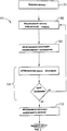
Краткое описание чертежейBrief Description of the Drawings
Фиг.1 изображает блок-схему емкостного зонда иFigure 1 depicts a block diagram of a capacitive probe and
Фиг.2 изображает блок-схему способа измерения частоты и смещения области многоцикловой усталости компонента с помощью емкостного зонда, изображенного на Фиг.1.FIG. 2 depicts a flowchart of a method for measuring the frequency and displacement of a multi-cycle fatigue region of a component using the capacitive probe of FIG. 1.
Лучший вариант осуществления изобретенияThe best embodiment of the invention
Фиг.1 является блок-схемой емкостного зонда 10, используемого для измерения частоты и смещения для проведения испытания на многоцикловую усталостную долговечность компонента (не изображен). В одном из вариантов осуществления изобретения емкостный зонд 10 измеряет частоту и смещение для проведения испытания на многоцикловую усталостную долговечность лопатки газотурбинного двигателя (не изображена). Емкостный зонд 10 действует в замкнутой системе управления и содержит печатную плату (не изображена), включающую в себя генератор 14, приемную схему 16, детектор произведения 18 и несколько усилителей 20 коэффициента усиления. В одном из вариантов осуществления данного изобретения печатная плата содержит пластину заземления (не изображена) для сведения к минимуму шума, наводимого в печатной плате.Figure 1 is a block diagram of a capacitive probe 10 used to measure frequency and bias for testing the multi-cycle fatigue life of a component (not shown). In one embodiment of the invention, a capacitive probe 10 measures the frequency and displacement for conducting the multi-cycle fatigue life of a gas turbine engine blade (not shown). The capacitive probe 10 operates in a closed-loop control system and contains a printed circuit board (not shown), including a generator 14, a receiving circuit 16, a product detector 18, and several amplification amplifiers 20. In one embodiment of the invention, the circuit board comprises a ground plate (not shown) to minimize noise induced in the circuit board.
Кварцевой генератор 14 содержит кристалл (не показан), который формирует единый регулируемый выходной сигнал частоты, который является постоянным. Соответственно, поскольку генератор 14 не является многовибраторной схемой без внешней синхронизации, выходной частотный сигнал от генератора 14 не уходит по мере того, как емкостный зонд 10 перемещается физически ближе к или дальше от компонента, испытываемого на усталость. Согласно одному из вариантов осуществления генератор 14 является генератором частоты 5 МГц модели HS-100P, который выпускает компания Vishay Intertechnology, Inc., Malvern, Pennsylvania.The crystal oscillator 14 contains a crystal (not shown) that generates a single adjustable frequency output signal that is constant. Accordingly, since the oscillator 14 is not a multivibrator circuit without external synchronization, the output frequency signal from the oscillator 14 does not go away as the capacitive probe 10 moves physically closer to or further from the component being tested for fatigue. In one embodiment, the oscillator 14 is a 5 MHz frequency generator of the HS-100P model manufactured by Vishay Intertechnology, Inc., Malvern, Pennsylvania.
Приемная схема 16 содержит настроенный мост для измерения емкости или мост Уитсона 24, содержащий по меньшей мере один конденсатор 26 переменной емкости. Емкостный зонд 10 функционирует в качестве четвертого конденсатора для моста Уитстона 26. Конденсатор 26 переменной емкости также обеспечивает возможность регулирования и уравновешивания эффекта электрической емкости для обеспечения сдвига постоянного напряжения в целях формирования нуля моста 24 для измерения емкости. В приводимом в качестве примера варианте осуществления настроенный мост 24 для измерения емкости также содержит два конденсатора 28 емкостью 30 пФ, а конденсатор 26 переменной емкости является конденсатором переменной емкости 5-25 пФ, который выпускает компания Johanson Manufacturing Corp., Boonton, New Jersey.The receiver circuit 16 includes a tuned bridge for measuring capacitance or a Witson bridge 24 containing at least one variable capacitor 26. The capacitance probe 10 functions as the fourth capacitor for the Wheatstone bridge 26. The variable capacitor 26 also provides the ability to control and balance the effect of the electric capacitance to provide a DC voltage shift to zero the bridge 24 to measure capacitance. In an exemplary embodiment, the tuned bridge 24 for capacitance measurement also contains two 30 pF capacitors 28, and the variable capacitor 26 is a 5-25 pF variable capacitor manufactured by Johanson Manufacturing Corp., Boonton, New Jersey.
Детектор 18 произведения принимает выходной сигнал от приемной схемы 16 и детектирует амплитудно-модулированное произведение сигналов с генератора 14. Детектор 18 произведения также подавляет нежелательные частоты перед тем, как ретранслировать сигнал от детектора 18 произведения. В одном из вариантов осуществления данного изобретения детектором 18 произведения является уравновешенный модулятор/демодулятор модели МС1496, выпускаемый компанией Motorola, Inc., Austin, Texas.The product detector 18 receives the output signal from the receiving circuit 16 and detects an amplitude-modulated product of the signals from the generator 14. The product detector 18 also suppresses undesirable frequencies before relaying the signal from the product detector 18. In one embodiment, the product detector 18 is a MC1496 balanced modulator / demodulator manufactured by Motorola, Inc., Austin, Texas.
На печатной плате смонтированы два усилителя 20 коэффициента усиления. Первый усилитель 40 коэффициента усиления является усилителем коэффициента усиления 50:1 и принимает выходной сигнал с детектора 18 произведения. Первый усилитель 40 коэффициента усиления содержит два светодиодных устройства (не изображены) для визуального указания обнаруживаемого сдвига постоянного напряжения на выходе первого усилителя 40 коэффициента усиления. Когда светодиоды запитываются и освещаются, оператор может отрегулировать мост 24 для измерения емкости, чтобы сформировать нуль электрической емкости, и после регулирования оба светодиода отключают от питания и они гаснут. После формирования нуля электрической емкости выход емкостного зонда можно поместить вблизи испытываемого компонента, и при этом сдвиги постоянного напряжения происходить не будут.Two amplifiers 20 gain are mounted on the circuit board. The first gain amplifier 40 is a 50: 1 gain amplifier and receives an output from the product detector 18. The first gain amplifier 40 includes two LED devices (not shown) for visually indicating a detectable DC voltage offset at the output of the first gain amplifier 40. When the LEDs are energized and illuminated, the operator can adjust the bridge 24 to measure the capacitance to form a zero electric capacitance, and after regulation, both LEDs are disconnected from the power supply and they go out. After the zero formation of the electric capacitance, the output of the capacitive probe can be placed near the component under test, and no DC voltage shifts will occur.
Второй усилитель 42 коэффициента усиления является усилителем коэффициента усиления 200:1 и принимает выходной сигнал от первого усилителя 40 коэффициента усиления. Второй усилитель 42 коэффициента усиления является сдвоенным усилителем и выполнен с возможностью его регулирования, для исключения перегрузки или избыточного усиления выходного сигнала емкостного зонда. В одном из вариантов осуществления данного изобретения первый и второй усилители 40 и 42 коэффициента усиления, соответственно, содержат усилители модели LF356, выпускаемые компанией National Semiconductor, Santa Clara, California.The second gain amplifier 42 is a 200: 1 gain amplifier and receives an output signal from the first gain amplifier 40. The second gain amplifier 42 is a dual amplifier and is configured to control it to prevent overload or excessive amplification of the output signal of the capacitive probe. In one embodiment of the invention, the first and second gain amplifiers 40 and 42 respectively comprise LF356 amplifiers sold by National Semiconductor, Santa Clara, California.
Во время проведения испытания компонента на усталость, в частности на многоцикловую усталость, компонент устанавливают на вибростенде (не изображен), и генератор (не изображен) используют для сообщения компоненту вибрации на собственной частоте в разомкнутом режиме. Емкостный зонд 10 прикладывают к компоненту, и зонд отслеживает изменения частоты и амплитуды компонента в режиме замкнутой системы управления. Зонд 10 прикрепляют к стенду (не изображен) с утяжеленным основанием, и во время испытания на долговечность его удерживают в нужном положении на стенде. Во время проведения испытания по мере того, как компонент устает и собственная резонансная частота снижается, емкостный зонд 10 передает изменения амплитуды на генератор вибростенда. Нагревание из-за электромагнитной индукции, электромагнитные помехи, шум, вносимые компонентом во время проведения испытания, исключают с помощью детектора 18 произведения. Помимо этого, усилители 40 и 42 коэффициента усиления обеспечивают возможность свести к нулю емкостный эффект во время увеличения и центрирования динамического диапазона выходного сигнала. Центрирование динамического диапазона выходного сигнала с помощью усилителей 40 и 42 коэффициента усиления обеспечивает стабильность замкнутой системы управления емкостного зонда. В результате этого зонд 10 можно установить прилегаемым к испытываемому компоненту и после формирования нуля мост 24 для измерения емкости сдвиги постоянного напряжения уменьшают во время испытания на долговечность относительно усталости.During the test of the component for fatigue, in particular for multi-cycle fatigue, the component is mounted on a vibrating stand (not shown), and a generator (not shown) is used to communicate the vibration component at its natural frequency in open mode. A capacitive probe 10 is applied to the component, and the probe monitors changes in the frequency and amplitude of the component in a closed-loop control system. The probe 10 is attached to a stand (not shown) with a weighted base, and during a durability test it is held in position on the stand. During the test, as the component gets tired and the natural resonant frequency decreases, the capacitive probe 10 transmits the amplitude changes to the oscillator. Heating due to electromagnetic induction, electromagnetic interference, noise introduced by the component during the test, exclude using the detector 18 of the product. In addition, gain amplifiers 40 and 42 provide the ability to nullify the capacitive effect while increasing and centering the dynamic range of the output signal. Centering the dynamic range of the output signal using amplifiers 40 and 42 gain provides stability to the closed control system of the capacitive probe. As a result of this, the probe 10 can be installed adjacent to the component under test, and after zeroing the bridge 24 to measure the capacitance, the DC voltage shifts are reduced during the durability test with respect to fatigue.
Для проведения испытания на долговечность другого компонента (не изображен) первый компонент снимают с вибростенда и на него устанавливают новый компонент. После установки на испытательном стенде нового компонента емкостный зонд 10 устанавливают в контакте с новым компонентом и медленно перемещают на некоторое расстояние от компонента до некоторой точки, в которой светодиоды отключают от питания. В этой точке, известной как нулевая точка, емкостный зонд 10 находится на том же расстоянии от нового компонента в ходе текущего испытания на усталость, на котором емкостный зонд 10 находился во время предыдущего испытания на усталость первого компонента. Амплитуда выходного сигнала зависит от расстояния зонда от компонента. Поскольку расстояния являются одинаковыми во время обоих испытаний и являются легко повторимыми, то для испытания многих компонентов перекалибровка или регулирования по смещению не являются необходимыми, за счет чего от испытания к испытанию обеспечивают одинаковую характерную амплитуду динамического диапазона.To conduct a durability test of another component (not shown), the first component is removed from the shaker and a new component is installed on it. After installing a new component on the test bench, the capacitive probe 10 is placed in contact with the new component and slowly moved a certain distance from the component to a point at which the LEDs are disconnected from the power supply. At this point, known as the zero point, the capacitive probe 10 is at the same distance from the new component during the current fatigue test at which the capacitive probe 10 was located during the previous fatigue test of the first component. The amplitude of the output signal depends on the distance of the probe from the component. Since the distances are the same during both tests and are easily repeatable, recalibration or bias adjustment is not necessary for testing many components, which ensures the same characteristic dynamic range amplitude from test to test.
Фиг.2 является блок-схемой способа 60, используемого для измерения частоты и смещения для испытания на многоцикловую усталость компонента (не изображен) с помощью емкостного зонда (не изображен на Фиг.2), который изображен в Фиг.1. Сначала, после фиксации компонента на испытательном стенде, емкостный зонд на этапе 70 передает единую частоту. В оном из вариантов осуществления емкостный зонд содержит кварцевый генератор (не изображен), содержит кристалл (не изображен), который формирует управляемый выходной частотный сигнал. В одном из вариантов осуществления генератором является генератор синхроимпульсов 5 МГц.FIG. 2 is a flow chart of a
Мост для измерения емкости (не изображен) регулируют на этапе 80 для приема передаваемой 70 единой частоты. Регулирование на этапе 80 моста для измерения емкости в целях приема частоты также регулирует емкостный эффект таким образом, что сдвиг постоянного напряжения в усилителе коэффициента усиления (не изображен) первого каскада становится нулевым. В одном из вариантов осуществления мост для измерения емкости регулируют на этапе 80 для приема изменений емкости на частоте 5 МГц.A capacitance measuring bridge (not shown) is adjusted in
После регулирования на этапе 80 моста для измерения емкости с целью приема единой передаваемой на этапе 70 частоты амплитудно-модулированное значение произведения сигналов с генератора детектируют на этапе 90 с помощью детектора произведения (не изображен в Фиг.2). Детектор произведения также подавляет на этапе 92 любые нежелательные частоты до ретранслирования сигнала. В одном из вариантов осуществления детектор произведения обнаруживает на этапе 90 только амплитудно-модулированный сигнал частотой 5 МГц.After adjusting at
Детектор произведения ретранслирует сигнал на первый усилитель коэффициента усиления (не изображен на фиг.2), который обнаруживает на этапе 100 сдвиг постоянного напряжения выходного сигнала первого усилителя коэффициента усиления. В одном из вариантов осуществления первый усилитель коэффициента усиления содержит пару светодиодов, которые освещаются, когда сдвиг постоянного напряжения обнаруживают на этапе 100 на первом усилителе коэффициента усиления. Если какое-либо смещение постоянного напряжения обнаруживают на этапе 100 на первом усилителе коэффициента усиления, то оператор может отрегулировать на этапе 80 мост для измерения емкости, чтобы свести к нулю эффект электрической емкости до ретранслирования сигнала с детектора произведения. При этом регулирование моста на этапе 50 для измерения емкости для сведения к нулю эффекта электрической емкости также центрирует динамический диапазон выходного сигнала, для стабилизирования замкнутой системы, в результате этого выход емкостного зонда можно установить прилегающим к испытываемому компоненту, после того, как на этапе 80 мост регулируют для сведения к нулю эффекта электрической емкости, сдвиги постоянного напряжения уменьшаются.The product detector relays the signal to the first gain amplifier (not shown in FIG. 2), which detects in step 100 a DC voltage offset of the output signal of the first gain amplifier. In one embodiment, the first gain amplifier comprises a pair of LEDs that are lit when a DC voltage shift is detected in
Последний этап способа 60 подразумевает использование второго усилителя коэффициента усиления (не изображен в Фиг.2), который регулируют на этапе 110, для исключения перегрузки или избыточного усиления выходного сигнала емкостного зонда. Поскольку амплитуда выходного сигнала емкостного зонда зависит от расстояния емкостного зонда до компонента, перекалибровка при испытании разных компонентов не является необходимой. В результате этого характерная амплитуда динамического диапазона остается постоянной во время испытания различных компонентов, и объем регулирования емкостного зонда по смещению уменьшается.The last step of
Описываемый выше способ измерения частоты и смещения испытания компонента на многоцикловую усталостную долговечность является рентабельным и очень надежным. Используемый для осуществления этого способа емкостный зонд точно измеряет частоту и смешение компонента. При этом поскольку емкостный зонд регулируют в целях подавления нежелательного шума, удается уменьшить сдвиги потенциально нарушающие, постоянное напряжение, в результате чего емкостный зонд можно устанавливать вблизи компонента в целях точного измерения частоты и смещения компонента во время проведения испытания на многоцикловую усталость.The method described above for measuring the frequency and bias of testing a component for high cycle fatigue life is cost-effective and very reliable. The capacitive probe used to implement this method accurately measures the frequency and mixing of the component. Moreover, since the capacitive probe is controlled in order to suppress unwanted noise, it is possible to reduce the shifts that potentially violate the constant voltage, as a result of which the capacitive probe can be installed near the component in order to accurately measure the frequency and component displacement during the multi-cycle fatigue test.
Несмотря на то что данное изобретение изложено применительно к конкретным вариантам осуществления, специалистам в данной области техники представляется очевидным, что данное изобретение может быть осуществлено с изменениями в рамках заявленной формулы.Although the invention has been set forth with reference to specific embodiments, it will be apparent to those skilled in the art that the invention may be implemented with changes within the scope of the claimed claims.
Claims (19)
Applications Claiming Priority (2)
| Application Number | Priority Date | Filing Date | Title |
|---|---|---|---|
| US09/576,286 US6431000B1 (en) | 2000-05-23 | 2000-05-23 | Method and apparatus for high cycle fatigue life test |
| US09/576,286 | 2000-05-23 |
Publications (2)
| Publication Number | Publication Date |
|---|---|
| RU2001114061A RU2001114061A (en) | 2003-06-10 |
| RU2265818C2 true RU2265818C2 (en) | 2005-12-10 |
Family
ID=24303750
Family Applications (1)
| Application Number | Title | Priority Date | Filing Date |
|---|---|---|---|
| RU2001114061/28A RU2265818C2 (en) | 2000-05-23 | 2001-05-22 | Method and device for fatigue durability testing |
Country Status (5)
| Country | Link |
|---|---|
| US (1) | US6431000B1 (en) |
| EP (1) | EP1158284A3 (en) |
| JP (1) | JP4647836B2 (en) |
| IL (1) | IL143190A (en) |
| RU (1) | RU2265818C2 (en) |
Cited By (1)
| Publication number | Priority date | Publication date | Assignee | Title |
|---|---|---|---|---|
| RU2443993C1 (en) * | 2010-11-02 | 2012-02-27 | Государственное образовательное учреждение высшего профессионального образования "Уфимский государственный авиационный технический университет" | Method of fatigue tests of metal samples |
Families Citing this family (2)
| Publication number | Priority date | Publication date | Assignee | Title |
|---|---|---|---|---|
| US7271583B2 (en) * | 2005-04-04 | 2007-09-18 | General Electric Company | Systems and methods for decoding a signal |
| DE112007002378T5 (en) | 2006-10-24 | 2009-09-03 | Bradley Fixtures Corp., Menomonee Falls | Capacitive measurement for washroom fittings |
Citations (6)
| Publication number | Priority date | Publication date | Assignee | Title |
|---|---|---|---|---|
| SU150549A1 (en) * | 1961-11-18 | 1961-11-30 | Б.В. Васильев | Device for measuring the resonant frequency and damping factor of solid materials |
| SU820365A1 (en) * | 1980-01-02 | 1981-04-07 | Государственный Ордена Трудовогокрасного Знамени Гидрологическийинститут | Capacitive probe for devices to measure the change in the level of conductive liquids |
| SU1205065A1 (en) * | 1983-08-04 | 1986-01-15 | Ленинградский Ордена Ленина Политехнический Институт Им.М.И.Калинина | Capacitance-to-frequency converter |
| SU1499259A1 (en) * | 1987-09-21 | 1989-08-07 | Военная Инженерная Радиотехническая Академия Противовоздушной Обороны Им.Маршала Советского Союза Л.А.Говорова | Apparatus for measuring average speed of frequency and linearity change of modulation characteristics of frequency-modulated generators |
| RU2100802C1 (en) * | 1995-06-09 | 1997-12-27 | Всероссийский научно-исследовательский институт маслоделия и сыроделия | Device with conductometric pickup |
| US6023980A (en) * | 1997-02-21 | 2000-02-15 | Southwest Research Institute | High-cycle fatigue test machine |
Family Cites Families (28)
| Publication number | Priority date | Publication date | Assignee | Title |
|---|---|---|---|---|
| US3379972A (en) * | 1963-12-26 | 1968-04-23 | Reliance Electric & Eng Co | Non-contacting displacement gauge having a feedback means for controlling the vibration amplitude of the probe |
| US3924456A (en) * | 1973-08-17 | 1975-12-09 | Western Electric Co | Methods and apparatus for detecting the presence of cracks in a workpiece by the use of stress waves emitted therefrom |
| US3983745A (en) * | 1975-08-08 | 1976-10-05 | Mts Systems Corporation | Test specimen crack correlator |
| US4118147A (en) | 1976-12-22 | 1978-10-03 | General Electric Company | Composite reinforcement of metallic airfoils |
| DE2821553C2 (en) * | 1978-05-17 | 1985-11-07 | MTU Motoren- und Turbinen-Union München GmbH, 8000 München | Procedure for the determination of cracks on test specimens in dynamic material testing |
| US4240047A (en) * | 1979-06-29 | 1980-12-16 | United Technologies Corporation | Mechanical resonator oscillator having redundant parallel drive circuits |
| US5049878A (en) * | 1981-05-13 | 1991-09-17 | Drexelbrook Engineering Company | Two-wire compensated level measuring instrument |
| JPS6165433A (en) * | 1984-09-07 | 1986-04-04 | Canon Inc | Inspecting device for object position of objective lens |
| DE3616390A1 (en) * | 1986-05-15 | 1987-11-19 | Uranit Gmbh | METHOD AND CIRCUIT FOR MEASURING THE NATURAL VIBRATION BEHAVIOR OF A ROTATING BODY |
| US4955269A (en) * | 1988-02-04 | 1990-09-11 | Westinghouse Electric Corp. | Turbine blade fatigue monitor |
| US4858473A (en) * | 1988-06-17 | 1989-08-22 | Trustees Of The University Of Pennsylvania | Miniature closed-loop dynamic universal mechanical testing machine |
| US5125265A (en) * | 1990-10-09 | 1992-06-30 | The United States Of America As Represented By The Secretary Of The Navy | Contamination capacitance probe system |
| US5146776A (en) * | 1990-11-26 | 1992-09-15 | Westinghouse Electric Corp. | Method for continuously calibrating an optical vibration sensor |
| US5354040A (en) | 1991-11-28 | 1994-10-11 | Mitsubishi Materials Corporation | Apparatus for closed cycle hydrogenation recovery and rehydrogenation |
| JP3225625B2 (en) * | 1992-09-25 | 2001-11-05 | 株式会社明電舎 | Back strain measuring device |
| US5442347A (en) * | 1993-01-25 | 1995-08-15 | The United States Of America As Represented By The Administrater, National Aeronautics & Space Administration | Double-driven shield capacitive type proximity sensor |
| FR2704109A1 (en) * | 1993-04-14 | 1994-10-21 | Philips Composants | Voltage controlled frequency oscillator. |
| US5557267A (en) * | 1993-04-23 | 1996-09-17 | Ade Corporation | Apparatus and methods for measurement system calibration |
| US5386442A (en) * | 1993-06-25 | 1995-01-31 | General Electric Company | Method and apparatus for controlling the load on double cantilever beam sensors |
| JPH08193937A (en) * | 1995-01-17 | 1996-07-30 | Hitachi Ltd | Electronic equipment and corrosion monitoring equipment |
| JPH0968460A (en) * | 1995-08-31 | 1997-03-11 | Sharp Corp | Device and method for detecting resonance point and method for estimating exhaustion |
| US6095755A (en) | 1996-11-26 | 2000-08-01 | United Technologies Corporation | Gas turbine engine airfoils having increased fatigue strength |
| JPH10185787A (en) * | 1996-12-26 | 1998-07-14 | Toyota Central Res & Dev Lab Inc | Fatigue test equipment |
| US5952890A (en) * | 1997-02-05 | 1999-09-14 | Fox Enterprises, Inc. | Crystal oscillator programmable with frequency-defining parameters |
| US6098022A (en) * | 1997-10-17 | 2000-08-01 | Test Devices, Inc. | Detecting anomalies in rotating components |
| US6194973B1 (en) * | 1998-05-29 | 2001-02-27 | Intel Corporation | Oscillator with automatic gain control |
| US6094105A (en) * | 1998-05-29 | 2000-07-25 | Intel Corporation | Oscillator with digital frequency control |
| US6203847B1 (en) | 1998-12-22 | 2001-03-20 | General Electric Company | Coating of a discrete selective surface of an article |
-
2000
- 2000-05-23 US US09/576,286 patent/US6431000B1/en not_active Expired - Fee Related
-
2001
- 2001-05-17 IL IL14319001A patent/IL143190A/en not_active IP Right Cessation
- 2001-05-21 EP EP01304439A patent/EP1158284A3/en not_active Withdrawn
- 2001-05-22 JP JP2001151786A patent/JP4647836B2/en not_active Expired - Fee Related
- 2001-05-22 RU RU2001114061/28A patent/RU2265818C2/en not_active IP Right Cessation
Patent Citations (6)
| Publication number | Priority date | Publication date | Assignee | Title |
|---|---|---|---|---|
| SU150549A1 (en) * | 1961-11-18 | 1961-11-30 | Б.В. Васильев | Device for measuring the resonant frequency and damping factor of solid materials |
| SU820365A1 (en) * | 1980-01-02 | 1981-04-07 | Государственный Ордена Трудовогокрасного Знамени Гидрологическийинститут | Capacitive probe for devices to measure the change in the level of conductive liquids |
| SU1205065A1 (en) * | 1983-08-04 | 1986-01-15 | Ленинградский Ордена Ленина Политехнический Институт Им.М.И.Калинина | Capacitance-to-frequency converter |
| SU1499259A1 (en) * | 1987-09-21 | 1989-08-07 | Военная Инженерная Радиотехническая Академия Противовоздушной Обороны Им.Маршала Советского Союза Л.А.Говорова | Apparatus for measuring average speed of frequency and linearity change of modulation characteristics of frequency-modulated generators |
| RU2100802C1 (en) * | 1995-06-09 | 1997-12-27 | Всероссийский научно-исследовательский институт маслоделия и сыроделия | Device with conductometric pickup |
| US6023980A (en) * | 1997-02-21 | 2000-02-15 | Southwest Research Institute | High-cycle fatigue test machine |
Cited By (1)
| Publication number | Priority date | Publication date | Assignee | Title |
|---|---|---|---|---|
| RU2443993C1 (en) * | 2010-11-02 | 2012-02-27 | Государственное образовательное учреждение высшего профессионального образования "Уфимский государственный авиационный технический университет" | Method of fatigue tests of metal samples |
Also Published As
| Publication number | Publication date |
|---|---|
| EP1158284A3 (en) | 2009-05-27 |
| US6431000B1 (en) | 2002-08-13 |
| JP2002116136A (en) | 2002-04-19 |
| JP4647836B2 (en) | 2011-03-09 |
| IL143190A (en) | 2005-06-19 |
| IL143190A0 (en) | 2002-04-21 |
| EP1158284A2 (en) | 2001-11-28 |
Similar Documents
| Publication | Publication Date | Title |
|---|---|---|
| US20100231208A1 (en) | Vibration and condition monitoring system and the parts thereof | |
| JP4177460B2 (en) | Resonance frequency tracking device | |
| US4002058A (en) | Method and apparatus for vibration of a specimen by controlled electromagnetic force | |
| JPS60142203A (en) | Device and method of measuring minute distance | |
| JPS5833551Y2 (en) | A device that measures the vibration of an object | |
| RU2265818C2 (en) | Method and device for fatigue durability testing | |
| US3715659A (en) | Inductive non-contact vibration analyzer which is independent of standoff distance | |
| CN1849517B (en) | Method and apparatus for measuring active, reactive power of system and module, impedance of electrical component | |
| US7053319B2 (en) | Electronic weighing apparatus utilizing surface acoustic waves using sensors operating at different frequencies, having temperature compensation, and a push oscillator | |
| Chitnis et al. | Optical fiber sensor for vibration amplitude measurement | |
| US20050007127A1 (en) | Digital RF bridge | |
| KR20050103966A (en) | Conductor inspecting device and conductor inspecting method | |
| RU1579231C (en) | Method for determining nonlinearity of null-point accelerometer with compensating section | |
| GB2337337A (en) | Method and means for determining the polarity of a capacitor | |
| SU1656477A1 (en) | Method for amplitude modulation meter calibration | |
| RU2115115C1 (en) | Process of detection of gas-saturated layers on titanium alloys and device for its implementation | |
| JP3519862B2 (en) | Vibration pickup calibration method and device | |
| RU2001114061A (en) | METHOD AND DEVICE FOR TESTING FOR MULTI-CYCLE FATIGUE Longevity | |
| KR920002179B1 (en) | Method and apparatus for detecting flaw with eddy current | |
| RU2184930C2 (en) | Eddy-current method of double-parameter test of articles | |
| US3434340A (en) | Method and apparatus for observing mechanical oscillations | |
| SU1160321A1 (en) | Device for measuring amplitude values of a.c.electric signals | |
| WO1995004256A1 (en) | Capacitive displacement sensor | |
| SU1377616A1 (en) | Device for contactless measurement of temperature of ferromagnetic bodies | |
| SU602790A1 (en) | Method of determining imaginary and real components of mechanical structure oscillation |
Legal Events
| Date | Code | Title | Description |
|---|---|---|---|
| MM4A | The patent is invalid due to non-payment of fees |
Effective date: 20140523 |