RU2263243C1 - Biplastic pipe - Google Patents
Biplastic pipe Download PDFInfo
- Publication number
- RU2263243C1 RU2263243C1 RU2004101385/06A RU2004101385A RU2263243C1 RU 2263243 C1 RU2263243 C1 RU 2263243C1 RU 2004101385/06 A RU2004101385/06 A RU 2004101385/06A RU 2004101385 A RU2004101385 A RU 2004101385A RU 2263243 C1 RU2263243 C1 RU 2263243C1
- Authority
- RU
- Russia
- Prior art keywords
- pipe
- pipes
- thermoplastic material
- lining layer
- winding
- Prior art date
Links
- -1 polyethylene Polymers 0.000 claims abstract description 20
- 239000004698 Polyethylene Substances 0.000 claims abstract description 15
- 229920000573 polyethylene Polymers 0.000 claims abstract description 15
- 238000004804 winding Methods 0.000 claims abstract description 14
- 229920001971 elastomer Polymers 0.000 claims abstract description 11
- 239000005060 rubber Substances 0.000 claims abstract description 11
- 239000012815 thermoplastic material Substances 0.000 claims abstract description 10
- 238000002844 melting Methods 0.000 claims abstract description 8
- 230000008018 melting Effects 0.000 claims abstract description 8
- 238000003466 welding Methods 0.000 claims abstract description 7
- 239000011521 glass Substances 0.000 claims abstract description 6
- 229920005989 resin Polymers 0.000 claims abstract description 6
- 239000011347 resin Substances 0.000 claims abstract description 6
- 239000004744 fabric Substances 0.000 claims abstract description 5
- 229920001568 phenolic resin Polymers 0.000 claims abstract description 5
- KXGFMDJXCMQABM-UHFFFAOYSA-N 2-methoxy-6-methylphenol Chemical compound [CH]OC1=CC=CC([CH])=C1O KXGFMDJXCMQABM-UHFFFAOYSA-N 0.000 claims abstract description 4
- 239000004743 Polypropylene Substances 0.000 claims abstract description 4
- 229920001155 polypropylene Polymers 0.000 claims abstract description 4
- 229920000915 polyvinyl chloride Polymers 0.000 claims abstract description 3
- 239000004800 polyvinyl chloride Substances 0.000 claims abstract description 3
- 239000011152 fibreglass Substances 0.000 claims description 11
- 230000004927 fusion Effects 0.000 claims description 4
- 238000010438 heat treatment Methods 0.000 claims description 4
- 230000015572 biosynthetic process Effects 0.000 claims description 3
- 239000000463 material Substances 0.000 abstract description 6
- 229920003023 plastic Polymers 0.000 abstract description 4
- 239000004033 plastic Substances 0.000 abstract description 4
- 239000000126 substance Substances 0.000 abstract description 4
- 230000000694 effects Effects 0.000 abstract description 3
- RRHGJUQNOFWUDK-UHFFFAOYSA-N Isoprene Chemical compound CC(=C)C=C RRHGJUQNOFWUDK-UHFFFAOYSA-N 0.000 abstract 1
- 238000003490 calendering Methods 0.000 abstract 1
- 238000011089 mechanical engineering Methods 0.000 abstract 1
- 229920001195 polyisoprene Polymers 0.000 abstract 1
- 239000010410 layer Substances 0.000 description 29
- 238000000034 method Methods 0.000 description 7
- 238000004519 manufacturing process Methods 0.000 description 6
- 239000002952 polymeric resin Substances 0.000 description 4
- 229920003002 synthetic resin Polymers 0.000 description 4
- 229910000831 Steel Inorganic materials 0.000 description 3
- 239000000853 adhesive Substances 0.000 description 3
- 230000001070 adhesive effect Effects 0.000 description 3
- 239000002985 plastic film Substances 0.000 description 3
- 229920006255 plastic film Polymers 0.000 description 3
- 239000010959 steel Substances 0.000 description 3
- 239000004593 Epoxy Substances 0.000 description 2
- 239000011230 binding agent Substances 0.000 description 2
- 230000008878 coupling Effects 0.000 description 2
- 238000010168 coupling process Methods 0.000 description 2
- 238000005859 coupling reaction Methods 0.000 description 2
- 239000003651 drinking water Substances 0.000 description 2
- 235000020188 drinking water Nutrition 0.000 description 2
- 239000012779 reinforcing material Substances 0.000 description 2
- 229920001169 thermoplastic Polymers 0.000 description 2
- 239000004416 thermosoftening plastic Substances 0.000 description 2
- 238000005299 abrasion Methods 0.000 description 1
- 239000012790 adhesive layer Substances 0.000 description 1
- 238000001266 bandaging Methods 0.000 description 1
- 230000007797 corrosion Effects 0.000 description 1
- 238000005260 corrosion Methods 0.000 description 1
- 230000006378 damage Effects 0.000 description 1
- 230000032798 delamination Effects 0.000 description 1
- 230000035622 drinking Effects 0.000 description 1
- 239000002657 fibrous material Substances 0.000 description 1
- SLGWESQGEUXWJQ-UHFFFAOYSA-N formaldehyde;phenol Chemical compound O=C.OC1=CC=CC=C1 SLGWESQGEUXWJQ-UHFFFAOYSA-N 0.000 description 1
- 239000012634 fragment Substances 0.000 description 1
- 235000011389 fruit/vegetable juice Nutrition 0.000 description 1
- 210000004072 lung Anatomy 0.000 description 1
- 238000012544 monitoring process Methods 0.000 description 1
- 230000035515 penetration Effects 0.000 description 1
- 229920000728 polyester Polymers 0.000 description 1
- 239000011253 protective coating Substances 0.000 description 1
- 230000001681 protective effect Effects 0.000 description 1
- 238000003908 quality control method Methods 0.000 description 1
- 230000005855 radiation Effects 0.000 description 1
- 238000007789 sealing Methods 0.000 description 1
- 229910001220 stainless steel Inorganic materials 0.000 description 1
- 239000010935 stainless steel Substances 0.000 description 1
- 238000005728 strengthening Methods 0.000 description 1
- 238000011179 visual inspection Methods 0.000 description 1
- XLYOFNOQVPJJNP-UHFFFAOYSA-N water Substances O XLYOFNOQVPJJNP-UHFFFAOYSA-N 0.000 description 1
Images

Landscapes
- Lining Or Joining Of Plastics Or The Like (AREA)
- Laminated Bodies (AREA)
Abstract
Description
Изобретение относится к области жилищно-коммунального хозяйства (ЖКХ) и к другим отраслям народного хозяйства преимущественно для транспортировки питьевых продуктов (воды, соков, и т.п.), в том числе и высокоагрессивных сред.The invention relates to the field of housing and communal services (Housing and Communal Services) and to other sectors of the economy mainly for the transportation of drinking products (water, juice, etc.), including highly aggressive environments.
В ЖКХ применяют для транспортировки питьевой воды стальные и в последние десятилетия полиэтиленовые трубы. Стальные трубы в процессе эксплуатации подвергаются коррозии, что приводит к снижению качества питьевой воды и к аварийным ситуациям при выходе труб из строя.In housing and communal services, steel and, in recent decades, polyethylene pipes have been used to transport drinking water. Steel pipes undergo corrosion during operation, which leads to a decrease in the quality of drinking water and to emergency situations when the pipes fail.
Полиэтиленовые трубы (ГОСТ 18599-2001; патент РФ 2161749, МПК 7 F 16 L 9/12, 10.01.2001) намного долговечней стальных. Однако из-за небольшой прочности полиэтиленовые трубы требуют значительного увеличения толщины стенок, особенно для труб диаметром 400 мм и выше. Увеличение толщины стенок приводит к ужесточению требований по сварке их между собой, т.е. к качеству сварного шва.Polyethylene pipes (GOST 18599-2001; RF patent 2161749, IPC 7 F 16 L 9/12, 01/10/2001) are much more durable than steel pipes. However, due to their low strength, polyethylene pipes require a significant increase in wall thickness, especially for pipes with a diameter of 400 mm and above. An increase in wall thickness leads to stricter requirements for welding them together, i.e. to the quality of the weld.
Соединение полиэтиленовых труб осуществляют методом сварки с использованием дорогого оборудования, в особенности для труб диаметром 400 мм и более. Проверка качества сварного шва также требует специального оборудования и специалистов высокой квалификации.The connection of polyethylene pipes is carried out by welding using expensive equipment, in particular for pipes with a diameter of 400 mm or more. Quality control of the weld also requires special equipment and highly qualified specialists.
Другим недостатком полиэтиленовых труб является их подверженность ультрафиолетовому облучению. Это требует жестких мер при хранении и транспортировке труб.Another disadvantage of polyethylene pipes is their exposure to ultraviolet radiation. This requires tough measures when storing and transporting pipes.
С целью повышения прочности полиэтиленовых труб последние армируют по наружной поверхности различными волокнистыми материалами и полимерными смолами, получая таким образом бипластмассовые трубы (см. патент РФ 2208735, 2154766, 2208732, МПК 7 F 16 L 9/12). Для этих целей используют как готовые трубы из термопластов, так и листы, свариваемые по оси образуемой трубы.In order to increase the strength of polyethylene pipes, the latter are reinforced on the outer surface with various fibrous materials and polymer resins, thus obtaining biplastic pipes (see RF patent 2208735, 2154766, 2208732, IPC 7 F 16 L 9/12). For these purposes, both finished pipes made of thermoplastics and sheets welded along the axis of the formed pipe are used.
Все эти бипластмассовые трубы имеют общий недостаток, заключающийся в том, что из-за большой разницы в коэффициенте термического линейного расширения разнородных по классу материалов (термопласты и армирующие материалы) трудно обеспечить адгезионную связь трубы и армирующего материала. За счет применения специальных клеев и смол эта адгезионная связь обеспечивается при достаточно небольших диапазонах (до диаметра 200-250 мм). При больших диаметрах в процессе эксплуатации от воздействия перепада температуры окружающей и транспортируемой среды, а также от воздействия радиальных напряжений происходит расслоение труб по адгезионному слою. Это приводит в конечном итоге к выходу трубы из строя.All these bi-plastic pipes have a common drawback, which is that because of the large difference in the coefficient of thermal linear expansion of heterogeneous materials (thermoplastics and reinforcing materials), it is difficult to provide an adhesive bond between the pipe and the reinforcing material. Due to the use of special adhesives and resins, this adhesive bond is ensured at fairly small ranges (up to a diameter of 200-250 mm). With large diameters during operation, from the influence of the temperature difference of the environment and the transported medium, as well as from the effect of radial stresses, the tubes are stratified along the adhesive layer. This ultimately leads to the failure of the pipe.
Из патента RU 2166145, МПК 7 F 16 L 9/12, 27.04.2001, взятого за прототип, известна бипластмассовая труба с защитным (футеровочным) слоем, выполненным в виде концентрических слоев химически и абразивостойкой резины, уложенными в каждом слое по спирали с нахлестом, и соединено с силовым каркасом из стеклопластика с помощью промежуточной системы слоев, которая состоит из концентрических слоев не пропитанного связующим низкоплотного материала с возможностью проникновения в него прилегающего слоя защитного покрытия с образованием прочного механического сцепления с силовым корпусом (стеклопластиком). С целью удержания футеровочного слоя (резины) с силовым корпусом с определенным шагом имеются подпорные кольца. Кольца имеют форму прямоугольного треугольника, изготовлены из стеклопластика на основе эпоксидных связующих и расположены непосредственно в контакте с транспортируемой средой.From the patent RU 2166145, IPC 7 F 16 L 9/12, 04/27/2001, taken as a prototype, a biplastic pipe with a protective (lining) layer made in the form of concentric layers of chemically and abrasion-resistant rubber laid in each layer in a spiral with an overlap is known , and is connected to the fiberglass power frame using an intermediate layer system, which consists of concentric layers of a low-density material not impregnated with a binder with the possibility of penetration of an adjacent layer of a protective coating into it with the formation of a durable mechanical tsepleniya with power body (GRP). In order to hold the lining layer (rubber) with a power housing with a certain step, there are retaining rings. The rings are in the shape of a rectangular triangle, made of fiberglass based on epoxy binders and are located directly in contact with the transported medium.
Данная труба имеет такие же недостатки, что указанные выше для бипластмассовых труб. Другим недостатком является то, что подпорные кольца непосредственно соприкасаются с транспортируемой средой. Этот факт снижает химическую стойкость трубы в целом из-за меньшей химической стойкости подпорного кольца по сравнению с резиновым (футеровочным) слоем трубы. Подпорные кольца с футеровочным слоем (резиной) и сам футеровочный слой связан с силовым корпусом (стеклопластиком) трубы только за счет механического сцепления (пористости), т.е. имеют границу раздела двух материалов.This pipe has the same disadvantages as indicated above for biplast pipes. Another disadvantage is that the retaining rings are in direct contact with the transported medium. This fact reduces the chemical resistance of the pipe as a whole due to the lower chemical resistance of the retaining ring compared with the rubber (lining) layer of the pipe. Retaining rings with a lining layer (rubber) and the lining layer itself are connected to the power housing (fiberglass) of the pipe only due to mechanical adhesion (porosity), i.e. have a boundary between two materials.
Таким образом, воздействие перепада температур и радиальные нагрузки в процессе эксплуатации трубы приводят к микротрещинам и в последующем выходу из строя трубы. Другим, немаловажным фактором по изготовлению данной трубы (прототипа) является высокая технологическая сложность, что приводит к высокой цене трубы, сравнимой с ценой трубы из нержавеющей стали.Thus, the effects of temperature extremes and radial loads during the operation of the pipe lead to microcracks and subsequent failure of the pipe. Another important factor in the manufacture of this pipe (prototype) is the high technological complexity, which leads to a high price of the pipe, comparable to the price of a stainless steel pipe.
Задачей, решаемой заявленным изобретением, является технический результат, заключающийся в простом, надежном и экономичном способе изготовления бипластмассовой трубы практически любого необходимого диаметра.The problem solved by the claimed invention is a technical result, which consists in a simple, reliable and economical method of manufacturing a biplast plastic pipe of almost any required diameter.
Решение упомянутой выше задачи достигается тем, что в бипластмассовой трубе, имеющей футеровочный слой, несущий, слой из стеклопластика и запорные кольца вдоль оси трубы, не контактирующие с транспортируемой средой, футеровочный слой образован намоткой на дорн термопластичного материала до толщины 1,5÷10 мм с образованием Т-образных запорных колец с последующими намоткой стеклянной ткани, пропитанной фенолформальдегидной смолой, и отверждением смолы, а также оплавлением термпопластичного материала при температуре 140÷180°С. При этом запорные кольца расположены вдоль оси трубы так, что отношение шага, с которым они расположены, к диаметру трубы составляет 0,15÷3.The solution to the above problem is achieved by the fact that in a biplastic pipe having a lining layer bearing, a layer of fiberglass and locking rings along the axis of the pipe that are not in contact with the transported medium, the lining layer is formed by winding a thermoplastic material mandrel to a thickness of 1.5 ÷ 10 mm with the formation of T-shaped locking rings with the subsequent winding of a glass cloth impregnated with phenol-formaldehyde resin, and curing the resin, as well as fusion of thermoplastic material at a temperature of 140 ÷ 180 ° C. In this case, the locking rings are located along the axis of the pipe so that the ratio of the pitch with which they are located to the diameter of the pipe is 0.15 ÷ 3.
В качестве термопластичного материала использована сырая каландрованная резина толщиной 1÷3 мм на основе различных каучуков или полиэтиленовая, или полипропиленовая, или поливинилхлоридная пленка.As a thermoplastic material, crude calendared
Труба имеет раструбы по концам для соединения труб между собой с последующим оплавлением футеровочного слоя в месте контакта на протяжении 30÷150 мм в раструбной части с помощью нагревательных лент.The pipe has sockets at the ends for connecting the pipes to each other, followed by melting of the lining layer at the contact point for 30 ÷ 150 mm in the socket part using heating tapes.
Для усиления соединения труб использована муфта-бандаж на наружной поверхности раструбной части.To strengthen the connection of the pipes, a coupling bandage was used on the outer surface of the socket part.
Соединение труб между собой усилено сваркой нержавеющих вкладышей.The connection between the pipes is reinforced by welding stainless inserts.
Т-образное сечение запорных колец по длине футеровочного слоя трубы позволяет проводить изготовление труб практически неограниченного диаметра без опасения отслоения футеровочного слоя от несущего стеклопластикового слоя. Это достигается двумя факторами. Первым является то, что запорные кольца Т-образного сечения позволяют дополнительно компенсировать усилия теплового расширения футеровочного слоя. Вторым фактором является дополнительная механическая связь футеровочного слоя с несущим стеклопластиковым слоем за счет верхней опоры Т-образного сечения запорного кольца.A T-shaped section of the locking rings along the length of the lining layer of the pipe allows the production of pipes of almost unlimited diameter without fear of delamination of the lining layer from the supporting fiberglass layer. This is achieved by two factors. The first is that the locking rings of the T-section can additionally compensate for the thermal expansion forces of the lining layer. The second factor is the additional mechanical connection of the lining layer with the supporting fiberglass layer due to the upper support of the T-shaped section of the locking ring.
Использование полиэтиленовой пленки для образования футеровочного слоя трубы позволяет регулировать его толщину в необходимом направлении, т.е. иметь толщину 1,5÷10 мм.Using a polyethylene film to form a lining layer of the pipe allows you to adjust its thickness in the desired direction, i.e. have a thickness of 1.5 ÷ 10 mm.
Соединение труб между собой раструбным способом с последующим оплавлением полиэтиленового футеровочного слоя в месте контакта длиной 30÷150 мм позволяет проводить быстрое и качественное соединение труб. При оплавлении не происходит химической деструкции полиэтилена в месте соединения, как это происходит при сварке полиэтиленовых труб. Такой метод соединения (оплавления) не требует специальных приборов и специалистов для проведения контроля места соединения труб. Достаточным контролем оплавления места соединения является простой визуальный осмотр, показывающий однородность материала места оплавления футеровочного слоя в раструбной части трубы.Connecting pipes to each other in a bell-shaped manner, followed by melting of the polyethylene lining layer at the contact point with a length of 30 ÷ 150 mm, allows for quick and high-quality pipe connection. During reflow, there is no chemical destruction of polyethylene at the junction, as is the case when welding polyethylene pipes. This method of connection (reflow) does not require special devices and specialists for monitoring the place of connection of pipes. A sufficient control of the fusion of the joint is a simple visual inspection showing the uniformity of the material of the fusion of the lining layer in the socket part of the pipe.
Усиление места соединения труб между собой после оплавления футеровочного слоя в раструбной части трубы проводят несколькими способами:Strengthening the joints between the pipes after melting the lining layer in the socket part of the pipe is carried out in several ways:
- путем бандажирования (обмотки) места стыка стеклянной лентой, пропитанной в полимерной смоле холодного отверждения;- by banding (winding) the junction of a glass tape impregnated in a polymer resin of cold curing;
- с помощью полиэтиленовой (или из другого материала) муфты, которая состоит из двух частей. Одна часть установлена на выступе конуса одной трубы, другая ее часть на раструбном выступе второй (с которой соединяется) трубы;- using a polyethylene (or other material) coupling, which consists of two parts. One part is mounted on the protrusion of the cone of one pipe, its other part on the bell-shaped protrusion of the second (with which it is connected) pipe;
- соединение осуществляется сваркой нержавеющих вкладышей между собой в раструбной части трубы. Вкладыши укладываются в раструбную и конусную части трубы при ее изготовлении.- the connection is made by welding stainless inserts between each other in the socket part of the pipe. The liners are placed in the bell and conical parts of the pipe during its manufacture.
Изобретение иллюстрируется чертежами, где на фиг.1 представлен фрагмент продольного сечения бипластмассовой трубы.The invention is illustrated by drawings, where in Fig.1 shows a fragment of a longitudinal section of a biplastic pipe.
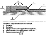
На фиг.2 - раструбное соединение бипластмассовых труб.Figure 2 - socket connection of biplast pipes.
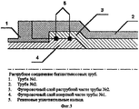
На фиг.3 - раструбное соединение бипластмассовых труб с резиновым уплотнителем.Figure 3 - socket connection of biplastic pipes with a rubber seal.
На фиг.4 - раструбное соединение бипластмассовых труб с бандажированием.Figure 4 - socket connection of biplastic pipes with banding.
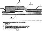
На фиг.5 - раструбное соединение бипластмассовых труб с нержавеющими вкладышами.Figure 5 - bell-shaped connection of biplastic pipes with stainless liners.
Пример конкретного изготовления бипластмассовой трубы.An example of a specific fabrication of a biplast pipe.
На подготовленный дорн диаметром 1000 мм и длиной 3 м наматывается полиэтиленовая пленка (ГОСТ 10354-73) толщиной 0,15 мм в количестве 10 слоев (см. фиг.1, поз.1). Затем с шагом 700 мм также полиэтиленовой пленкой наматываются кольца шириной 20÷30 мм и высотой 3÷5 мм. Межкольцевое пространство заматывается стеклотканью марки НПГ-210 (ТУ 648-00202956-30-94), пропитанной фенолформальдегидной смолой марки СФЖ-304 (ГОСТ 20907). Стеклоткань наматывается на толщину 4 мм. Затем на полиэтиленовые кольца наматывается полиэтиленовая пленка шириной 60÷90 мм, образуя тем самым основание (опору) Т-образного сечения запорного кольца (поз.2). Высота намотки этого основания 3÷4 мм. Затем по всей поверхности дорна проводят намотку стеклотканью НПГ-210, пропитанной смолой СФЖ-304. При этой намотке толщина слоя стеклопластика (поз.2) составляет 6 мм. Окончательной операцией намотки является намотка по всей поверхности трубы термоусаживающейся полипропиленовой ткани марки ТПЛ (ТУ 8237-019-05766623-2001).On the prepared mandrel with a diameter of 1000 mm and a length of 3 m is wound a plastic film (GOST 10354-73) with a thickness of 0.15 mm in an amount of 10 layers (see figure 1, item 1). Then, with a pitch of 700 mm, rings with a width of 20–30 mm and a height of 3–5 mm are also wound with plastic film. The inter-ring space is wrapped with glass fabric brand NPG-210 (TU 648-00202956-30-94), impregnated with phenol-formaldehyde resin brand SFZH-304 (GOST 20907). Fiberglass is wound to a thickness of 4 mm. Then, a plastic film 60–90 mm wide is wound on polyethylene rings, thereby forming the base (support) of the T-shaped section of the locking ring (pos. 2). The winding height of this base is 3 ÷ 4 mm. Then, over the entire surface of the mandrel, they are wound with NPG-210 fiberglass, impregnated with SFZh-304 resin. With this winding, the thickness of the fiberglass layer (item 2) is 6 mm. The final winding operation is winding over the entire surface of the pipe heat-shrinkable polypropylene fabric brand TPL (TU 8237-019-05766623-2001).
После окончания процесса намотки труба вместе с дорном помещаются в камеру отверждения, где происходит оплавление полиэтиленовой пленки и отверждение смолы при температуре 140÷180°С в течение 90 минут. По окончании процесса отверждения труба с дорном выгружается из камеры отверждения и затем готовая труба снимается с дорна.After the winding process is completed, the pipe together with the mandrel is placed in the curing chamber, where the polyethylene film is melted and the resin is cured at a temperature of 140 ÷ 180 ° C for 90 minutes. At the end of the curing process, the pipe with the mandrel is unloaded from the curing chamber and then the finished pipe is removed from the mandrel.
Примеры способов соединения труб между собой:Examples of methods for connecting pipes to each other:
Пример №1:Example No. 1:
Соединение труб между собой осуществляется раструбным способом (см. фиг.2). Раструбная и конусная части трубы изготавливаются в процессе намотки трубы. Соединение труб (поз.1 и 2) происходит за счет оплавления футеровочного слоя раструбной (3) и конусной (4) частей трубы. Оплавление осуществляется с помощью нагревательной ленты (5) марки ЛУНГ (ТУ 3443-004-42235774-00), которая наматывается на наружную поверхность раструба трубы. При достижении температуры нагрева 200°С ее выдерживают в течение 15 мин. Контроль за температурой осуществляют с помощью переносного прибора марки ИТ 1511.The connection between the pipes is carried out by a bell-shaped method (see figure 2). The bell-shaped and conical parts of the pipe are made in the process of winding the pipe. The connection of the pipes (
Пример №2:Example No. 2:
Соединение труб между собой осуществляют аналогично примеру №1, за исключением того, что оплавление футеровочного слоя не проводят. Соединение труб происходит за счет резиновых уплотнительных колец (см. фиг.3, поз.5), которые укладываются в специальные канавки раструбной и конусной частей трубы. Эти канавки образуются в процессе намотки трубы.The connection between the pipes is carried out analogously to example No. 1, except that the lining of the lining layer is not carried out. The connection of the pipes occurs due to the rubber sealing rings (see figure 3, item 5), which fit into special grooves of the bell-shaped and conical parts of the pipe. These grooves are formed during the winding process of the pipe.
Пример №3:Example 3:
Соединение труб между собой осуществляют аналогично примеру №1 или примеру №2, за исключением того, что для усиления узла соединения труб проводят его бандажирование (см. фиг.4). Бандажирование (поз.5) заключается в обматывают раструба десятью слоями стеклоткани, пропитанной полимерной смолой холодного отверждения. В качестве полимерной смолы используют - полиэфирную, эпоксидную или фенолформальдегидную.The connection of the pipes to each other is carried out analogously to example No. 1 or example No. 2, except that to reinforce the node connecting the pipes carry out its banding (see figure 4). Bandaging (item 5) consists of wrapping a bell with ten layers of fiberglass impregnated with a cold cured polymer resin. As the polymer resin used - polyester, epoxy or phenol-formaldehyde.
Пример №5:Example No. 5:
Соединение труб между собой осуществляют аналогично примеру №1 или примеру №2, за исключением того, что для усиления узла соединения труб проводят сварку нержавеющих вкладышей (см. фиг.5). Вкладыши (поз. 5) укладываются в раструбную и конусную части трубы при ее изготовлении.The pipe connection to each other is carried out analogously to example No. 1 or example No. 2, except that in order to strengthen the pipe connection node, stainless inserts are welded (see figure 5). The liners (item 5) are placed in the bell and conical parts of the pipe during its manufacture.
Claims (6)
Priority Applications (1)
| Application Number | Priority Date | Filing Date | Title |
|---|---|---|---|
| RU2004101385/06A RU2263243C1 (en) | 2004-01-21 | 2004-01-21 | Biplastic pipe |
Applications Claiming Priority (1)
| Application Number | Priority Date | Filing Date | Title |
|---|---|---|---|
| RU2004101385/06A RU2263243C1 (en) | 2004-01-21 | 2004-01-21 | Biplastic pipe |
Publications (2)
| Publication Number | Publication Date |
|---|---|
| RU2004101385A RU2004101385A (en) | 2005-07-10 |
| RU2263243C1 true RU2263243C1 (en) | 2005-10-27 |
Family
ID=35837554
Family Applications (1)
| Application Number | Title | Priority Date | Filing Date |
|---|---|---|---|
| RU2004101385/06A RU2263243C1 (en) | 2004-01-21 | 2004-01-21 | Biplastic pipe |
Country Status (1)
| Country | Link |
|---|---|
| RU (1) | RU2263243C1 (en) |
Cited By (1)
| Publication number | Priority date | Publication date | Assignee | Title |
|---|---|---|---|---|
| RU2638670C1 (en) * | 2016-08-01 | 2017-12-15 | Федеральное государственное казенное учреждение "Войсковая часть 44239" | Ignition device body for hand grenade and method for its production |
Citations (5)
| Publication number | Priority date | Publication date | Assignee | Title |
|---|---|---|---|---|
| US3629028A (en) * | 1969-07-29 | 1971-12-21 | Universal Oil Prod Co | Method of making self-lubricating filament wound tube |
| GB1522240A (en) * | 1976-12-31 | 1978-08-23 | Ekstroem & Co Evaksystem Hande | Pipes and methods for their manufacture |
| RU2154766C1 (en) * | 1999-12-29 | 2000-08-20 | Закрытое акционерное общество "Пласт" | Tube from composite materials and method of its production |
| RU2161749C2 (en) * | 1995-04-28 | 2001-01-10 | ЭЛЕНАК ГмбХ | High-strength pipe made from ethylene-based polymer |
| RU2166145C1 (en) * | 1999-11-02 | 2001-04-27 | Кашин Сергей Михайлович | Composite-material pipe for transportation of gaseous and liquid products under high pressure and method of its manufacture (versions) |
-
2004
- 2004-01-21 RU RU2004101385/06A patent/RU2263243C1/en not_active IP Right Cessation
Patent Citations (5)
| Publication number | Priority date | Publication date | Assignee | Title |
|---|---|---|---|---|
| US3629028A (en) * | 1969-07-29 | 1971-12-21 | Universal Oil Prod Co | Method of making self-lubricating filament wound tube |
| GB1522240A (en) * | 1976-12-31 | 1978-08-23 | Ekstroem & Co Evaksystem Hande | Pipes and methods for their manufacture |
| RU2161749C2 (en) * | 1995-04-28 | 2001-01-10 | ЭЛЕНАК ГмбХ | High-strength pipe made from ethylene-based polymer |
| RU2166145C1 (en) * | 1999-11-02 | 2001-04-27 | Кашин Сергей Михайлович | Composite-material pipe for transportation of gaseous and liquid products under high pressure and method of its manufacture (versions) |
| RU2154766C1 (en) * | 1999-12-29 | 2000-08-20 | Закрытое акционерное общество "Пласт" | Tube from composite materials and method of its production |
Cited By (1)
| Publication number | Priority date | Publication date | Assignee | Title |
|---|---|---|---|---|
| RU2638670C1 (en) * | 2016-08-01 | 2017-12-15 | Федеральное государственное казенное учреждение "Войсковая часть 44239" | Ignition device body for hand grenade and method for its production |
Also Published As
| Publication number | Publication date |
|---|---|
| RU2004101385A (en) | 2005-07-10 |
Similar Documents
| Publication | Publication Date | Title |
|---|---|---|
| EP1155256B1 (en) | A liner hose for reconstruction of conduits and pipelines and a method for manufacture thereof | |
| CN104781068B (en) | For reinforcing the lining and its manufacture method of pipeline | |
| US20200318761A1 (en) | High-pressure pipe with pultruded elements and method for producing the same | |
| CN108286627B (en) | Thermoplastic composite tube with multi-layer middle sheet layer | |
| US10221983B2 (en) | Subsea pipe-in-pipe structures | |
| MXPA00012490A (en) | A flexible composite pipe and a method for manufacturing same. | |
| CN104334950A (en) | Multilayer pipeline in a polymer material, device for manufacture of the multilayer pipeline and a method for manufacturing the multilayer pipeline | |
| AU2002320710B2 (en) | Composite Pipe Having a PTFE Inner Layer and a Covering Layer of a Fibre-reinforced Plastics Material | |
| RU2753377C2 (en) | Fitting element for use in restoration of pipelines and method for its manufacture | |
| RU2263243C1 (en) | Biplastic pipe | |
| CN112055797B (en) | Method of manufacturing lined pipe | |
| CN209638562U (en) | A kind of frp lining concrete composite pipe | |
| RU2069807C1 (en) | Pipe line made of composition material | |
| TWI327519B (en) | Slip collar | |
| GB2394017A (en) | Pipe-in-pipe flowline joint | |
| KR100851965B1 (en) | Steel reinforcement pipe coated with adhesive epoxy resin and its manufacturing method | |
| US10344904B2 (en) | Strengthened polyethylene tubular member | |
| CN222277718U (en) | Continuous fiber band grid structure reinforced thermoplastic water supply and drainage pressure composite pipe | |
| CN216643343U (en) | Adhesive plastic high-pressure composite pipe with continuous fiber winding and lapping structure | |
| US20190049056A1 (en) | Method for strengthening a polyethylene tubular member | |
| RU2340826C2 (en) | Tight pipe-shell | |
| RU20563U1 (en) | PIPE FOR SEWERAGE WASTE | |
| JPS6347476Y2 (en) | ||
| CN111183024A (en) | Reinforced polyethylene tubular members | |
| CN2580270Y (en) | Thermal contraction belt coated winding steel wire net buried plastic pipeline joint |
Legal Events
| Date | Code | Title | Description |
|---|---|---|---|
| MM4A | The patent is invalid due to non-payment of fees |
Effective date: 20060122 |