RU2257456C2 - Ship used for performing operations in underwater running well and method of offshore drilling at reduced hydrostatic pressure - Google Patents
Ship used for performing operations in underwater running well and method of offshore drilling at reduced hydrostatic pressure Download PDFInfo
- Publication number
- RU2257456C2 RU2257456C2 RU2002113372/03A RU2002113372A RU2257456C2 RU 2257456 C2 RU2257456 C2 RU 2257456C2 RU 2002113372/03 A RU2002113372/03 A RU 2002113372/03A RU 2002113372 A RU2002113372 A RU 2002113372A RU 2257456 C2 RU2257456 C2 RU 2257456C2
- Authority
- RU
- Russia
- Prior art keywords
- well
- equipment
- drilling
- tanker
- operations
- Prior art date
Links
Images
Classifications
-
- E—FIXED CONSTRUCTIONS
- E21—EARTH DRILLING; MINING
- E21B—EARTH DRILLING, e.g. DEEP DRILLING; OBTAINING OIL, GAS, WATER, SOLUBLE OR MELTABLE MATERIALS OR A SLURRY OF MINERALS FROM WELLS
- E21B15/00—Supports for the drilling machine, e.g. derricks or masts
- E21B15/02—Supports for the drilling machine, e.g. derricks or masts specially adapted for underwater drilling
-
- B—PERFORMING OPERATIONS; TRANSPORTING
- B63—SHIPS OR OTHER WATERBORNE VESSELS; RELATED EQUIPMENT
- B63B—SHIPS OR OTHER WATERBORNE VESSELS; EQUIPMENT FOR SHIPPING
- B63B35/00—Vessels or similar floating structures specially adapted for specific purposes and not otherwise provided for
- B63B35/44—Floating buildings, stores, drilling platforms, or workshops, e.g. carrying water-oil separating devices
- B63B35/4413—Floating drilling platforms, e.g. carrying water-oil separating devices
-
- E—FIXED CONSTRUCTIONS
- E21—EARTH DRILLING; MINING
- E21B—EARTH DRILLING, e.g. DEEP DRILLING; OBTAINING OIL, GAS, WATER, SOLUBLE OR MELTABLE MATERIALS OR A SLURRY OF MINERALS FROM WELLS
- E21B21/00—Methods or apparatus for flushing boreholes, e.g. by use of exhaust air from motor
- E21B21/08—Controlling or monitoring pressure or flow of drilling fluid, e.g. automatic filling of boreholes, automatic control of bottom pressure
- E21B21/085—Underbalanced techniques, i.e. where borehole fluid pressure is below formation pressure
Abstract
Description
Настоящее изобретение относится к судну, предназначенному для проведения операций в подводной действующей скважине.The present invention relates to a vessel designed for operations in an underwater active well.
Скважины для добычи углеводородов создают путем использования бурового снаряда вращательного бурения. Буровой снаряд вращательного бурения приводится в действие с поверхности, при этом в случае морской (подводной) скважины, как правило, с буровой установки, смонтированной на платформе, расположенной над скважиной. Платформа может быть установлена на морском дне или может представлять собой полупогружной агрегат, местоположение которого может поддерживаться почти во всех наиболее экстремальных условиях. После завершения бурения скважину закрепляют трубами для обеспечения возможности прохода жидких углеводородов через насосно-компрессорные трубы из любого местонахождения углеводородов, в которое проходят трубы. В некоторых пластах углеводородные текучие среды и вода занимают один и тот же коллектор, при этом углеводородные текучие среды образуют слой на поверхности воды. Если насосно-компрессорная колонна скважины проникает в пласт, исходно занятый углеводородными текучими средами, то по мере прохода текучей среды в насосно-компрессорную колонну скважины может иметь место явление, известное как “образование водяного конуса”, то есть поверхность раздела между жидкими углеводородами и водой наклоняется вверх в сторону скважины. Это происходит в результате градиентов давления, создаваемых внутри продуктивного пласта, вследствие наличия потока текучих сред через пласт в насосно-компрессорную колонну скважины. Если вершина конусообразной поверхности раздела достигнет насосно-компрессорной колонны скважины, большие объемы воды будут поступать в насосно-компрессорную колонну скважины, вызывая снижение производительности добычи жидких углеводородов [дебита скважины] и увеличение затрат на отделение добываемых углеводородных текучих сред от воды.Wells for hydrocarbon production are created by using a rotary drilling tool. A rotary drill is driven from the surface, and in the case of an offshore well, as a rule, from a drilling rig mounted on a platform located above the well. The platform can be installed on the seabed or can be a semi-submersible unit, the location of which can be maintained in almost all the most extreme conditions. After drilling is completed, the well is secured with pipes to allow liquid hydrocarbons to pass through the tubing from any hydrocarbon location into which the pipes pass. In some formations, hydrocarbon fluids and water occupy the same reservoir, with hydrocarbon fluids forming a layer on the surface of the water. If a well’s tubing string penetrates into a reservoir initially occupied by hydrocarbon fluids, then as the fluid flows into the well’s tubing string, a phenomenon known as “water cone formation”, that is, an interface between liquid hydrocarbons and water, can occur. leans up towards the well. This occurs as a result of pressure gradients created within the reservoir, due to the presence of fluid flow through the reservoir into the well tubing. If the apex of the conical interface reaches the tubing string, large volumes of water will flow into the tubing string, causing a reduction in liquid hydrocarbon production [well flow rate] and an increase in the cost of separating the produced hydrocarbon fluids from the water.
Известно, что в скважинах, в которых образование водяного конуса является проблемой, осуществляют дополнительные операции бурения для предотвращения или сведения к минимуму образования водяного конуса. Например, буровой снаряд для забоя ствола скважины может быть использован для бурения поперечных каналов, проходящих в пласт, несущий жидкие углеводороды. Это может быть достигнуто путем использования обычных способов бурения, но такие способы требуют простоя скважины и часто требуют удаления колонны, закрепляющей скважину. Это связано с существенными затратами и риском. Кроме того, пласт, содержащий жидкие углеводороды, может быть поврежден буровыми растворами, требуемыми для дополнительных операций бурения.It is known that in wells in which the formation of a water cone is a problem, additional drilling operations are carried out to prevent or minimize the formation of a water cone. For example, a drill for borehole bottomhole can be used to drill transverse channels passing into a reservoir carrying liquid hydrocarbons. This can be achieved by using conventional drilling methods, but such methods require a downtime of the well and often require the removal of the column securing the well. This is associated with significant costs and risks. In addition, a formation containing liquid hydrocarbons may be damaged by the drilling fluids required for additional drilling operations.
Для предотвращения потерь или повреждений скважины, вызванных бурением, был разработан усовершенствованный способ бурения, обеспечивающий выполнение технически трудного бурения без существенного риска повреждения пласта. Этот способ называют бурением при пониженном гидростатическом давлении в стволе скважины. При таком бурении скважина постоянно остается действующей (с положительным давлением на поверхности). Этого можно добиться путем использования легкого бурового раствора или на основе регулирования газлифта путем использования специально сконструированного и изготовленного противовыбросового превентора. Чистый буровой раствор закачивают вниз в скважину и смешивают с текучими средами пласта, при этом обеспечивается возможность потока этих сред, проходящего вверх в скважине и переносящего буровой шлам на поверхность. После этого пять фаз (газ, нефть, пластовую воду, буровой раствор и твердые частицы, образующиеся при бурении) разделяют. На суше этот процесс является простым, поскольку имеется достаточно места. Однако оборудование является крупногабаритным, и его считали неподходящим для морских операций.To prevent loss or damage to the well caused by drilling, an improved drilling method has been developed that enables technically difficult drilling to be performed without a significant risk of formation damage. This method is called drilling under reduced hydrostatic pressure in the wellbore. With such drilling, the well remains active (with positive surface pressure). This can be achieved by using light drilling mud or by regulating gas lift by using a specially designed and manufactured blowout preventer. Pure drilling fluid is pumped down into the well and mixed with the formation fluids, while this allows the flow of these media to flow upward in the well and transfer the drill cuttings to the surface. After that, the five phases (gas, oil, produced water, drilling fluid and solid particles formed during drilling) are separated. On land, this process is simple as there is enough space. However, the equipment is bulky and was considered unsuitable for offshore operations.
Бурениe при пониженном гидростатическом давлении в стволе скважины может выполняться путем использования обычного вращательного бурения или бурения с применением намотанных труб. В секторе Северного моря, принадлежащем Великобритании, четыре скважины были пробурены с использованием вращательного бурения при пониженном гидростатическом давлении в стволе скважины, но это было возможно только благодаря использованию сравнительно больших неподвижных (опирающихся на морское дно) платформ. На суше использовалось бурение с применением намотанных труб. В этих известных случаях применения длинную бесшовную трубу, которая хранится на барабане, вталкивают в скважину с помощью инжектора против направления действия давления в действующей скважине. Турбобур устанавливают на нижнем конце трубы, и гидравлическое давление подают к турбобуру по трубе. Это приводит в действие турбобур и обеспечивает возможность выполнения бурения. Малый диаметр трубы (как правило, от 1 до 2 7/8") позволяет пропускать трубу через существующие трубы, служащие для закрепления скважины (обычно это называется заканчиванием), так что отсутствует необходимость в значительных затратах и рисках, связанных с удалением таких труб, служащих для закрепления скважины.Drilling under reduced hydrostatic pressure in the wellbore can be accomplished using conventional rotary drilling or coiled tubing drilling. In the North Sea sector, owned by the United Kingdom, four wells were drilled using rotary drilling with reduced hydrostatic pressure in the wellbore, but this was only possible thanks to the use of relatively large fixed (supported on the seabed) platforms. On land drilling using coiled pipes was used. In these known applications, a long seamless pipe that is stored on a drum is pushed into the well by means of an injector against the direction of pressure in the current well. A turbo-drill is installed at the lower end of the pipe, and hydraulic pressure is supplied to the turbo-drill through the pipe. This drives the turbodrill and enables drilling. The small diameter of the pipe (usually 1 to 2 7/8 ") allows the pipe to pass through existing pipes used to secure the well (usually called completion), so that there is no need for significant costs and risks associated with the removal of such pipes, employees for fixing the well.
Имеются легкие суда, предназначенные для проведения операций в скважине, которые обеспечивают возможность выполнения таких операций, как обслуживание скважин, например, выполнения геофизических исследований в скважинах (каротажа) и общего технического обслуживания и ремонтных работ. Однако такие суда нельзя рассматривать как подходящие платформы для проведения операций в скважинах, требующих бурения, поскольку они не являются достаточно устойчивыми для таких операций и, кроме того, не позволяют выполнять бурение при пониженном гидростатическом давлении в стволе скважины, так как они слишком малы для манипулирования и транспортировки тех объемов материала, которые имеют место при таком бурении. Кроме того, легкие суда, предназначенные для проведения операций в скважинах, требуют больших капитальных вложений по сравнению с их возможной отдачей, в частности потому, что они сильно уязвимы при плохих погодных условиях, так что затраты на проведение операций в скважинах являются относительно большими, а время использования сравнительно малым. Естественно, можно использовать полупогружные буровые платформы, предназначенные для проведения операций в скважинах, но полупогружные буровые платформы пока еще нельзя использовать для бурения при пониженном гидростатическом давлении в стволе скважины. Даже такой подход потребовал бы наличия поддерживающих судов для приема добытых жидкостей и твердых веществ. Соответственно, не было предпринято никаких попыток использовать бурение при пониженном гидростатическом давлении в стволе скважины, осуществляемое с применением намотанных труб с плавучих средств.There are light vessels designed for well operations that provide the ability to perform operations such as servicing wells, for example, performing geophysical surveys in wells (logging) and general maintenance and repair work. However, such vessels cannot be considered as suitable platforms for operations in wells that require drilling, since they are not stable enough for such operations and, moreover, do not allow drilling with reduced hydrostatic pressure in the wellbore, since they are too small to handle and transportation of the volumes of material that occur during such drilling. In addition, light vessels designed for operations in wells require large capital investments in comparison with their possible returns, in particular because they are highly vulnerable in bad weather conditions, so the costs of operations in wells are relatively large, and usage time is relatively small. Naturally, you can use semi-submersible drilling platforms designed for operations in wells, but semi-submersible drilling platforms cannot yet be used for drilling at low hydrostatic pressure in the wellbore. Even such an approach would require the support of vessels to receive the extracted liquids and solids. Accordingly, no attempt has been made to use drilling under reduced hydrostatic pressure in the wellbore using wound pipes from floating equipment.
Целью настоящего изобретения является разработка судна, предназначенного для проведения операций в подводной скважине, обеспечивающего повторный вход в существующие эксплутационные скважины так, чтобы обеспечить возможность проведения операций в скважине без вывода скважины из ее эксплутационного состояния и без загрязнения подводного оборудования для добычи потоками, возникающими при проведении операций в скважине, например, твердыми частицами, образующимися при бурении.The aim of the present invention is to develop a vessel designed for operations in a subsea well, providing re-entry into existing production wells so as to enable operations in the well without removing the well from its operational state and without contaminating the underwater equipment for production by flows arising from operations in the well, for example, by solid particles generated during drilling.
В соответствии с настоящим, изобретением разработано судно, предназначенное для проведения операций в подводной скважине, содержащее выполненный с возможностью динамического позиционирования танкер и оборудование, предназначенное для непосредственного проведения операций в подводной скважине, установленное на палубе танкера и содержащее оборудование для невращательного бурения при пониженном гидростатическом давлении в стволе скважины и оборудование для отделения жидких углеводородов, соединенное с резервуарами-хранилищами танкера, так что отделенные жидкие углеводороды могут храниться на танкере.In accordance with the present invention, a vessel is designed for conducting operations in a subsea well, comprising a dynamically positioning tanker and equipment for directly conducting operations in a subsea well, mounted on the deck of a tanker, and containing equipment for non-rotary drilling under reduced hydrostatic pressure in the wellbore and equipment for the separation of liquid hydrocarbons, connected to the storage tanks tan kera so that the separated liquid hydrocarbons can be stored on the tanker.
В соответствии с изобретением также разработан способ морского бурения при пониженном гидростатическом давлении в стволе скважины, при котором танкер, имеющий оборудование, предназначенное для непосредственного проведения операций в подводной скважине и установленное на его палубе, динамически позиционируют над водоотделяющей колонной, проходящей от подводной скважины, оборудование, предназначенное для проведения операций в скважине, соединяют с водоотделяющей колонной и выполняют невращательное бурение при пониженном гидростатическом давлении в стволе скважины, образующуюся в результате многофазную смесь разделяют на танкере, и отделенные жидкие углеводороды хранят в резервуарах-хранилищах танкера.In accordance with the invention, a method for offshore drilling with reduced hydrostatic pressure in the wellbore is also developed, in which a tanker having equipment designed to directly conduct operations in a subsea well and installed on its deck is dynamically positioned above a water separating column passing from the subsea well, designed for operations in the well, connected to the riser and perform non-rotary drilling with low hydrostat pressure in the wellbore, the resulting multiphase mixture is separated on the tanker, and the separated liquid hydrocarbons are stored in tanker storage tanks.
Термин “невращательное бурение” используется здесь для обозначения любого бурения, при котором отсутствует вращение бурильной колонны, включая бурение при пониженном гидростатическом давлении в стволе скважины, при котором используется вращающаяся бурильная головка, приводимая в действие с помощью невращающейся бурильной колонны, но невращательное бурение не ограничивается бурением только такого типа.The term “non-rotary drilling” is used herein to mean any drilling in which there is no rotation of the drill string, including drilling under reduced hydrostatic pressure in the wellbore, in which a rotary drill head is driven by a non-rotating drill string, but non-rotary drilling is not limited. drilling only this type.
Оборудование, предназначенное для проведения операций в скважине, может быть смонтировано на надстройке над главной палубой обычного танкера снабжения. Оборудование для невращательного бурения при пониженном гидростатическом давлении в стволе скважины может быть выполнено с применением намотанных труб и может быть установлено рядом с передвижной платформой, приспособленной смещаться в забортное положение над водоотделяющей колонной скважины, к которой должно быть присоединено указанное оборудование. Таким образом, проведение операций в скважине может быть осуществлено посредством динамического позиционирования танкера снабжения рядом с водоотделяющей колонной скважины, перемещения передвижной платформы в забортное положение, присоединения оборудования для бурения с применением намотанных труб к водоотделяющей колонне и выполнения необходимого проведения операций в скважине, к которой присоединена водоотделяющая колонна, при этом текучие среды и твердые частицы, полученные в процессе бурения с применением намотанных труб, разделяются с помощью оборудования, установленного на надстройке, и осуществляется перемещение жидких углеводородов из оборудования для отделения в предназначенный для хранения трюм танкера снабжения.Equipment designed for operations in the well can be mounted on a superstructure above the main deck of a conventional supply tanker. Non-rotational drilling equipment with reduced hydrostatic pressure in the wellbore can be made using coiled tubing and can be installed next to a mobile platform adapted to move outboard above the water separating well string to which the specified equipment should be attached. Thus, operations in the well can be carried out by dynamically positioning the supply tanker near the water separating column of the well, moving the mobile platform to the outboard position, attaching drilling equipment using coiled pipes to the water separating column, and performing the necessary operations in the well to which it is connected a water separating column, while fluids and solid particles obtained during drilling using wound pipes, times are separated using the equipment installed on the superstructure, and liquid hydrocarbons are transferred from the separation equipment to the hold of the supply tanker.
В качестве альтернативы выполнению передвижной платформы, способной смещаться в заборное [навесное] положение, оборудование для невращательного бурения при пониженном гидростатическом давлении в стволе скважины может быть выполнено с применением намотанных труб и установлено рядом с буровой шахтой, расположенной над водоотделяющей колонной скважины, к которой должно быть присоединено указанное оборудование.As an alternative to the implementation of a mobile platform, capable of shifting to the intake [hinged] position, equipment for non-rotary drilling with reduced hydrostatic pressure in the wellbore can be performed using wound pipes and installed next to the drill shaft located above the water separating column of the well to which The specified equipment must be connected.
Далее с помощью примера будут описаны варианты осуществления настоящего изобретения со ссылкой на сопровождающие чертежи, на которых изображено следующее:Next, by way of example, embodiments of the present invention will be described with reference to the accompanying drawings, in which the following is shown:
Фиг.1 изображает схематичный вид, иллюстрирующий образование водяного конуса;Figure 1 is a schematic view illustrating the formation of a water cone;
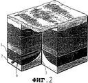
Фиг.2 - вид, показывающий результаты бурения с применением накатанных труб в конструкции, показанной на фиг.1 для увеличения интенсивности добычи жидких углеводородов;Figure 2 is a view showing the results of drilling using rolled pipes in the structure shown in figure 1 to increase the intensity of production of liquid hydrocarbons;
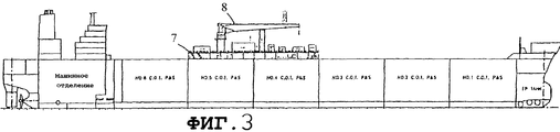
Фиг.3 - вид сбоку известного танкера снабжения, который применяется в Северном море и на котором установлено оборудование, предназначенное для непосредственного проведения операций в скважине, в соответствии с настоящим изобретением;Figure 3 is a side view of a known supply tanker, which is used in the North Sea and on which equipment is designed for direct operations in the well, in accordance with the present invention;
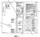
Фиг.4 - схему расположения оборудования, предназначенного для непосредственного проведения операций в скважине, показанного на виде сбоку на фиг.3;Figure 4 - arrangement of equipment designed for direct operations in the well, shown in side view in figure 3;
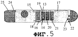
Фиг.5 - схематичный вид танкера, в котором образованы буровые шахты, посредством которых может выполняться бурение с применением намотанных труб.5 is a schematic view of a tanker in which drill shafts are formed by which drilling using coiled pipes can be performed.
На фиг.1 показан ряд пластов, содержащих несущий углеводороды пласт 1, который расположен над водоносным пластом 2. Скважина 3 пробурена через пласты 1, 2. Давление в пласте, несущем жидкие углеводороды, и в водоносном пласте такое, что создается поток, проходящий в скважину 3. В результате этого потока вокруг скважины 3 образуется “водяной конус” 4, и в результате коническая поверхность 5 раздела создается между жидкими углеводородами и водой. Если скважина 3 закреплена стальными трубами до верхней части пласта 1 и водяной конус дойдет до зоны рядом с закрепленной частью скважины, будут получены большие объемы воды. Очевидно, что это очень невыгодно, и поэтому известно, что осуществляют проведение операций в скважине, в которой возникают проблемы из-за образования водяного конуса. На фиг.2 показаны результаты такого размещения.Figure 1 shows a series of formations containing hydrocarbon-bearing formation 1, which is located above the
На фиг.2 показано ответвление 6 скважины в процессе бурения его в пласте 1. Бурение такого ответвления 6 может обеспечить существенное улучшение соотношения добываемых жидкостей в пользу жидких углеводородов. Хорошо известно использование бурения с применением намотанных труб для создания ответвления, такого как ответвление 6 на фиг.2.Figure 2 shows the
Однако при использовании подобного способа необходимо поддерживать условия пониженного гидростатического давления в стволе скважины (то есть поддерживать положительное давление в верхней части скважины 3) для предотвращения повреждения скважины твердыми частицами, образующимися при бурении. Такие способы никогда не использовались при морском бурении, поскольку с таким объемом образующегося материала могли справляться только большие установки.However, when using this method, it is necessary to maintain conditions of reduced hydrostatic pressure in the wellbore (that is, maintain positive pressure in the upper part of the well 3) to prevent damage to the well by solid particles generated during drilling. Such methods have never been used in offshore drilling, since only large rigs could handle such a volume of material formed.
На фиг.3 показан танкер снабжения, в котором реализовано настоящее изобретение. Фиг.3 базируется на чертеже, взятом из работы “First Olsen Tankers”, и показывает танкер снабжения такого типа, который широко используется в Северном море. Единственным изменением, выполненным по отношению к стандартному танкеру снабжения, является установка надстройки 7 над главной палубой танкера, например, на высоте приблизительно 3 м для освобождения [от препятствий] установленных палубных клюзов и вентиляционных каналов. На этой надстройке смонтировано все оборудование, необходимое для непосредственного проведения операций в скважине, включая кран 8. Подробная схема расположения оборудования, установленного на надстройке 7 по фиг.3, показана на фиг.4.Figure 3 shows a supply tanker in which the present invention is implemented. Figure 3 is based on a drawing taken from the work of “First Olsen Tankers” and shows a supply tanker of the type that is widely used in the North Sea. The only change made with respect to the standard supply tanker is the installation of a
Как показано на фиг.4, передвижная платформа 9 установлена центрально на надстройке 7 рядом с портальным краном 10. Оборудование 11 для бурения с применением намотанных труб обычного вида установлено рядом с портальным краном 10. Блок 12 сепараторов и вспомогательное оборудование 13 для обеспечения бурения также установлено на надстройке 7. Все остальное оборудование, предназначенное для непосредственного проведения операций в скважине, также установлено на надстройке 7. Блок 12 сепараторов соединен с расположенным соответствующим образом блоком факельных установок, например, на корме судна (не показано) и с резервуарами-хранилищами (накопительными танками) танкера для обеспечения возможности накопления и хранения добываемых углеводородных текучих сред для последующей транспортировки.As shown in FIG. 4, a
При использовании танкер динамически позиционируют рядом с водоотделяющей колонной подводной скважины. После этого передвижную платформу 9 перемещают в забортное положение (не показано) над водоотделяющей колонной для обеспечения возможности подсоединения оборудования 11 для бурения к водоотделяющей колонне. Затем соответствующие вмешательства могут быть осуществлены через водоотделяющую колонну, и, в частности, бурение с применением намотанных труб может быть выполнено так, что будет получена многофазная смесь, которую впоследствии разделяют на ее отдельные фазы в блоке 12 сепараторов.In use, the tanker is dynamically positioned next to the underwater well riser. After that, the
Система, описанная со ссылкой на фиг.3 и 4, представляет собой большое достижение в морском бурении, испытании, удалении отходов и техническом обслуживании скважин. Грузовые трюмы танкеров могут быть использованы для накапливания добываемой нефти в процессе бурения при пониженном гидростатическом давлении в стволе скважины. Система может обеспечить непосредственный доступ к испытаниям подводных скважин в течение продолжительных периодов времени. Система может быть использована для испытаний, связанных с продолжительным нагнетанием воды, и также обеспечивает возможность удаления отходов в подводную скважину. Существующие системы, напротив, не обеспечивают возможности выполнения бурения с применением намотанных труб и накапливания добываемой нефти и требуют использования отдельного танкера снабжения, если в процессе бурения добывается нефть.The system described with reference to FIGS. 3 and 4 represents a major achievement in offshore drilling, testing, waste disposal and well maintenance. Cargo holds of tankers can be used to accumulate produced oil during drilling at reduced hydrostatic pressure in the wellbore. The system can provide direct access to subsea well testing over extended periods of time. The system can be used for tests related to continuous injection of water, and also provides the ability to remove waste into a subsea well. Existing systems, on the contrary, do not provide the possibility of drilling using coiled pipes and accumulating produced oil and require the use of a separate supply tanker if oil is produced during drilling.
Кроме того, сохраняются исходные элементы танкера снабжения, и поэтому судно может по-прежнему использоваться для чартерных перевозок, когда оно не применяется для осуществления непосредственного проведения операций в скважине. В результате в соответствии с изобретением предлагается решение проблемы обеспечения непосредственного проведения операций в скважине при осуществлении бурения с применением намотанных труб без существенных затрат, связанных со строительством и эксплуатацией специальных судов.In addition, the original elements of the supply tanker are retained, and therefore, the vessel can still be used for charter operations when it is not used for direct operations in the well. As a result, in accordance with the invention, it is proposed to solve the problem of providing direct operations in the well when drilling using coiled pipes without significant costs associated with the construction and operation of special vessels.
Типовой танкер снабжения, пригодный для работы в условиях Северного моря, с динамическим позиционированием может быть легко зафрахтован и оснащен новой палубой над установленными палубными клюзами и вентиляционными каналами. На этой палубе может быть установлено следующее соответствующее оборудование:A typical supply tanker, suitable for operation in the North Sea, with dynamic positioning, can be easily chartered and equipped with a new deck above installed deck gates and ventilation ducts. The following equipment may be installed on this deck:
устройство для манипулирования подъемником мачтового крана, установленного на передвижной платформе, с подводной панелью управления;a device for manipulating the mast crane hoist mounted on a mobile platform with an underwater control panel;
тумбы для оборудования, предназначенного для проведения операций в подводной скважине;pedestals for equipment intended for operations in a subsea well;
стеллаж для труб;pipe rack;
барабаны для намотанных труб, управляющее устройство и источник питания;drums for coiled pipes, control device and power source;
устройство для цементирования и смеситель;cementing device and mixer;
испытательное оборудование и контрольно-измерительная аппаратура, используемые при эксплуатации, включая штуцерный манифольд, подогреватель-эмульгатор, сепараторы, колонный компенсатор давления, предназначенный для дегазации, и свеча для сжигания газа;test equipment and instrumentation used during operation, including a choke manifold, an emulsifier heater, separators, a column pressure compensator designed for degassing, and a candle for burning gas;
резервуары для бурового раствора для глушения скважины;mud reservoirs for killing a well;
замкнутая система циркуляции, предназначенная для транспортировки бурового раствора и образующихся при бурении твердых частиц во время бурения при пониженном гидростатическом давлении в стволе скважины;a closed circulation system designed to transport drilling fluid and solid particles formed during drilling during drilling at reduced hydrostatic pressure in the wellbore;
резервуары-хранилища для химикатов и твердых отходов;storage tanks for chemicals and solid waste;
крановое оборудование для подводного оборудования и вспомогательные материалы;crane equipment for underwater equipment and auxiliary materials;
транспортные средства с дистанционным управлением для работы и наблюдения;vehicles with remote control for work and surveillance;
запасы воды для охлаждения и пожаротушения.water supplies for cooling and fire fighting.
Возможно, существует порядка 2000 подводных оснащенных скважин, эксплуатируемых в настоящее время. При использовании настоящего изобретения может быть обеспечен доступ в такие оснащенные скважины за сумму порядка 100000 долларов США в день в отличие от назначаемых в настоящее время сумм порядка от 200000 до 300000 долларов США в день. Таким образом, изобретение позволяет существенным образом повлиять на технические возможности индустрии морского бурения с учетом финансовых ограничений, с которыми сталкивается данная индустрия.Perhaps there are about 2,000 subsea equipped wells currently in operation. When using the present invention, access to such equipped wells can be provided for an amount of about $ 100,000 per day, unlike the currently assigned amounts of about $ 200,000 to $ 300,000 per day. Thus, the invention allows to significantly affect the technical capabilities of the offshore drilling industry, taking into account the financial constraints faced by this industry.
Технические решения в области бурения с применением намотанных труб включают использование оправдывающего затраты оборудования низа бурильной колонны, применяемого для типовых систем промывки буровым раствором, и оборудования низа бурильной колонны на вспомогательном канате, которое в полной мере использует преимущества бурения через трубы, включая применение пеногенераторов и пневматических систем. Настоящее изобретение обеспечивает возможность использования способов наземного бурения при пониженном гидростатическом давлении в стволе скважины для морского бурения, и при этом не требуется длительная доработка оборудования. Данное изобретение также обеспечивает возможность добычи значительных объемов углеводородов без необходимости использования дополнительных судов для накопления и хранения углеводородов, в результате чего уменьшается потребность в денежных средствах, и при этом одновременно избегают повреждений скважины в результате выполнения операций бурения. Параметры движения относительно большого танкера снабжения больше подходят для выполняемых с особой точностью операций бурения при пониженном гидростатическом давлении в стволе скважины, чем существующие относительно меньшие и обладающие большей плавучестью альтернативные суда. Это позволяет продлить время, в течение которого погодные условия позволяют работать, и уменьшить усталостные нагрузки, действующие на намотанные трубы, когда их подают из танкера в водоотделяющую колонну подводной скважины. Изобретение также обеспечивает возможность надлежащей очистки скважин после проведения операций, в результате чего избегают загрязнения иногда чувствительной системы, используемой для добычи. Создается возможность справляться с отходами, возникающими при бурении, оптимальным образом, и это может быть осуществлено относительно безопасно при условии наличия большого палубного пространства. Все эти преимущества недостижимы, если использовать обычную полупогружную платформу, или обычное специально сконструированное и изготовленное судно, предназначенное для проведения операций в скважине.Wound pipe drilling solutions include the use of cost-effective bottom-hole equipment used for typical mud flushing systems and bottom-hole equipment on an auxiliary wire that takes full advantage of pipe drilling, including the use of foam generators and pneumatic systems. The present invention provides the possibility of using methods of surface drilling at reduced hydrostatic pressure in the wellbore for offshore drilling, and it does not require long-term development of equipment. This invention also provides the possibility of producing significant volumes of hydrocarbons without the need for additional vessels for the accumulation and storage of hydrocarbons, thereby reducing the need for cash, while avoiding damage to the well as a result of drilling operations. The motion parameters of a relatively large supply tanker are more suitable for drilling operations performed with particular accuracy at reduced hydrostatic pressure in the wellbore than existing relatively smaller and more buoyant alternative vessels. This allows you to extend the time during which weather conditions allow you to work, and to reduce the fatigue loads acting on the wound pipes when they are fed from the tanker into the underwater well separating column. The invention also allows for proper cleaning of wells after operations, thereby avoiding contamination of the sometimes sensitive system used for production. The opportunity arises to cope with the waste arising from drilling in an optimal way, and this can be done relatively safely provided that there is a large deck space. All these advantages are unattainable if you use the usual semi-submersible platform, or the usual specially designed and manufactured vessel designed for operations in the well.
В варианте осуществления изобретения, описанном со ссылкой на фиг.3, 4, элементы, необходимые для реализации изобретения, установлены на передвижной платформе, которая может быть смещена в забортное положение. В альтернативной конструкции, проиллюстрированной на фиг.5, такие элементы установлены рядом с буровыми шахтами, проходящими через конструкцию обычного в других отношениях танкера.In the embodiment of the invention described with reference to figures 3, 4, the elements necessary for the implementation of the invention are mounted on a mobile platform, which can be shifted to the outboard position. In an alternative design illustrated in FIG. 5, such elements are mounted adjacent to drill shafts passing through the structure of a otherwise conventional tanker.
Как показано на фиг.5, две буровые шахты 13, 14 проходят вертикально через конструкцию модифицированного танкера снабжения. Три крана 15, 16, 17 могут проходить над буровыми шахтами и зонами, обозначающими клапанные коробки 18 грузовой системы танкера, модуль 19 мачтового крана и зону 20 монтажа. В зоне 21 размещены устройства для сжатия и обработки газа, в зоне 22 - грузовая стрела факельной установки, в зоне 23 - передвижная платформа для барабанного сепаратора [газоотделителя] факельной установки, и зона 24 представляет собой дополнительную зону монтажа, обслуживаемую краном 25.As shown in FIG. 5, two
Если использовать типовой двухкорпусной танкер снабжения, то модификации, необходимые для получения судна, схематично проиллюстрированного на фиг.5, которое может функционировать в соответствии с настоящим изобретением, будут включать в себя повышение способности к динамическому позиционированию, установку первой буровой шахты (8 м2) для выполнения операций в скважине, установку второй буровой шахты (4 м2), предназначенной для работы транспортных средств с дистанционным управлением, монтаж кранов, технологического оборудования и создание зон монтажа установленного на палубе оборудования и монтаж факельных установок и соответствующих средств обеспечения.If you use a typical double-hulled supply tanker, the modifications necessary to obtain the vessel, schematically illustrated in figure 5, which can function in accordance with the present invention, will include increasing the ability for dynamic positioning, installation of the first drilling shaft (8 m 2 ) for performing operations in a wellbore, the second setting moonpool (4 m 2), intended for vehicles with remote control, mounting of cranes, process equipment and CPNS areas of installation mounted on the deck of the equipment and installation of flares and the appropriate means to ensure.
Claims (5)
Applications Claiming Priority (2)
| Application Number | Priority Date | Filing Date | Title |
|---|---|---|---|
| GB9930450.3 | 1999-12-23 | ||
| GBGB9930450.3A GB9930450D0 (en) | 1999-12-23 | 1999-12-23 | Subsea well intervention vessel |
Publications (2)
| Publication Number | Publication Date |
|---|---|
| RU2002113372A RU2002113372A (en) | 2003-11-20 |
| RU2257456C2 true RU2257456C2 (en) | 2005-07-27 |
Family
ID=10866905
Family Applications (1)
| Application Number | Title | Priority Date | Filing Date |
|---|---|---|---|
| RU2002113372/03A RU2257456C2 (en) | 1999-12-23 | 2000-12-20 | Ship used for performing operations in underwater running well and method of offshore drilling at reduced hydrostatic pressure |
Country Status (24)
| Country | Link |
|---|---|
| US (1) | US6840322B2 (en) |
| EP (1) | EP1240404B1 (en) |
| JP (1) | JP2003518576A (en) |
| KR (1) | KR100799958B1 (en) |
| CN (1) | CN1228534C (en) |
| AP (1) | AP1370A (en) |
| AT (1) | ATE255674T1 (en) |
| AU (1) | AU779937B2 (en) |
| BR (1) | BR0016527B1 (en) |
| CA (1) | CA2392331C (en) |
| DE (1) | DE60006998T2 (en) |
| DK (1) | DK1240404T3 (en) |
| ES (1) | ES2211656T3 (en) |
| GB (2) | GB9930450D0 (en) |
| HK (1) | HK1047611B (en) |
| MX (1) | MXPA02006375A (en) |
| NO (1) | NO327209B1 (en) |
| NZ (1) | NZ518885A (en) |
| OA (1) | OA12127A (en) |
| PT (1) | PT1240404E (en) |
| RU (1) | RU2257456C2 (en) |
| TR (1) | TR200400337T4 (en) |
| WO (1) | WO2001048351A2 (en) |
| ZA (1) | ZA200203763B (en) |
Families Citing this family (59)
| Publication number | Priority date | Publication date | Assignee | Title |
|---|---|---|---|---|
| US7100710B2 (en) * | 1994-10-14 | 2006-09-05 | Weatherford/Lamb, Inc. | Methods and apparatus for cementing drill strings in place for one pass drilling and completion of oil and gas wells |
| US6868906B1 (en) * | 1994-10-14 | 2005-03-22 | Weatherford/Lamb, Inc. | Closed-loop conveyance systems for well servicing |
| US7108084B2 (en) * | 1994-10-14 | 2006-09-19 | Weatherford/Lamb, Inc. | Methods and apparatus for cementing drill strings in place for one pass drilling and completion of oil and gas wells |
| US7228901B2 (en) * | 1994-10-14 | 2007-06-12 | Weatherford/Lamb, Inc. | Method and apparatus for cementing drill strings in place for one pass drilling and completion of oil and gas wells |
| US7013997B2 (en) * | 1994-10-14 | 2006-03-21 | Weatherford/Lamb, Inc. | Methods and apparatus for cementing drill strings in place for one pass drilling and completion of oil and gas wells |
| US6742596B2 (en) * | 2001-05-17 | 2004-06-01 | Weatherford/Lamb, Inc. | Apparatus and methods for tubular makeup interlock |
| US6536520B1 (en) | 2000-04-17 | 2003-03-25 | Weatherford/Lamb, Inc. | Top drive casing system |
| US7509722B2 (en) * | 1997-09-02 | 2009-03-31 | Weatherford/Lamb, Inc. | Positioning and spinning device |
| GB9815809D0 (en) * | 1998-07-22 | 1998-09-16 | Appleton Robert P | Casing running tool |
| GB2340857A (en) * | 1998-08-24 | 2000-03-01 | Weatherford Lamb | An apparatus for facilitating the connection of tubulars and alignment with a top drive |
| US7188687B2 (en) * | 1998-12-22 | 2007-03-13 | Weatherford/Lamb, Inc. | Downhole filter |
| CA2356194C (en) * | 1998-12-22 | 2007-02-27 | Weatherford/Lamb, Inc. | Procedures and equipment for profiling and jointing of pipes |
| GB2345074A (en) * | 1998-12-24 | 2000-06-28 | Weatherford Lamb | Floating joint to facilitate the connection of tubulars using a top drive |
| GB2347441B (en) * | 1998-12-24 | 2003-03-05 | Weatherford Lamb | Apparatus and method for facilitating the connection of tubulars using a top drive |
| US6896075B2 (en) * | 2002-10-11 | 2005-05-24 | Weatherford/Lamb, Inc. | Apparatus and methods for drilling with casing |
| US7311148B2 (en) * | 1999-02-25 | 2007-12-25 | Weatherford/Lamb, Inc. | Methods and apparatus for wellbore construction and completion |
| CA2393754C (en) * | 1999-12-22 | 2009-10-20 | Weatherford/Lamb, Inc. | Drilling bit for drilling while running casing |
| US7334650B2 (en) * | 2000-04-13 | 2008-02-26 | Weatherford/Lamb, Inc. | Apparatus and methods for drilling a wellbore using casing |
| US7325610B2 (en) * | 2000-04-17 | 2008-02-05 | Weatherford/Lamb, Inc. | Methods and apparatus for handling and drilling with tubulars or casing |
| AU2003228214B2 (en) * | 2002-02-19 | 2007-11-22 | Varco I/P, Inc. | Subsea intervention system, method and components thereof |
| GB0206227D0 (en) * | 2002-03-16 | 2002-05-01 | Weatherford Lamb | Bore-lining and drilling |
| US6994176B2 (en) * | 2002-07-29 | 2006-02-07 | Weatherford/Lamb, Inc. | Adjustable rotating guides for spider or elevator |
| US6899186B2 (en) * | 2002-12-13 | 2005-05-31 | Weatherford/Lamb, Inc. | Apparatus and method of drilling with casing |
| US7303022B2 (en) * | 2002-10-11 | 2007-12-04 | Weatherford/Lamb, Inc. | Wired casing |
| US6968902B2 (en) * | 2002-11-12 | 2005-11-29 | Vetco Gray Inc. | Drilling and producing deep water subsea wells |
| US7380589B2 (en) * | 2002-12-13 | 2008-06-03 | Varco Shaffer, Inc. | Subsea coiled tubing injector with pressure compensation |
| USRE42877E1 (en) | 2003-02-07 | 2011-11-01 | Weatherford/Lamb, Inc. | Methods and apparatus for wellbore construction and completion |
| US7874352B2 (en) | 2003-03-05 | 2011-01-25 | Weatherford/Lamb, Inc. | Apparatus for gripping a tubular on a drilling rig |
| GB2416360B (en) * | 2003-03-05 | 2007-08-22 | Weatherford Lamb | Drilling with casing latch |
| GB2439427B (en) * | 2003-03-05 | 2008-02-13 | Weatherford Lamb | Casing running and drilling system |
| US7503397B2 (en) * | 2004-07-30 | 2009-03-17 | Weatherford/Lamb, Inc. | Apparatus and methods of setting and retrieving casing with drilling latch and bottom hole assembly |
| WO2004079147A2 (en) * | 2003-03-05 | 2004-09-16 | Weatherford/Lamb, Inc. | Method and apparatus for drilling with casing |
| US7370707B2 (en) * | 2003-04-04 | 2008-05-13 | Weatherford/Lamb, Inc. | Method and apparatus for handling wellbore tubulars |
| GB2436497B8 (en) | 2003-04-10 | 2007-12-17 | Vik Sandvik As | Method for loading/unloading a support vessel at an offshore installation. |
| US7650944B1 (en) * | 2003-07-11 | 2010-01-26 | Weatherford/Lamb, Inc. | Vessel for well intervention |
| US7264067B2 (en) * | 2003-10-03 | 2007-09-04 | Weatherford/Lamb, Inc. | Method of drilling and completing multiple wellbores inside a single caisson |
| NO329611B1 (en) * | 2004-07-20 | 2010-11-22 | Weatherford Lamb | Feeding Mater. |
| CA2532907C (en) * | 2005-01-12 | 2008-08-12 | Weatherford/Lamb, Inc. | One-position fill-up and circulating tool |
| CA2533115C (en) * | 2005-01-18 | 2010-06-08 | Weatherford/Lamb, Inc. | Top drive torque booster |
| US7225877B2 (en) * | 2005-04-05 | 2007-06-05 | Varco I/P, Inc. | Subsea intervention fluid transfer system |
| GB2437526A (en) * | 2006-04-27 | 2007-10-31 | Multi Operational Service Tank | A sub-sea well intervention vessel and method |
| GB2437647B (en) * | 2006-04-27 | 2011-02-09 | Weatherford Lamb | Torque sub for use with top drive |
| CA2867384C (en) | 2006-11-07 | 2016-06-07 | Charles R. Orbell | Method of drilling by installing multiple annular seals between a riser and a string |
| US7882902B2 (en) * | 2006-11-17 | 2011-02-08 | Weatherford/Lamb, Inc. | Top drive interlock |
| US7628224B2 (en) * | 2007-04-30 | 2009-12-08 | Kellogg Brown & Root Llc | Shallow/intermediate water multipurpose floating platform for arctic environments |
| US20090199591A1 (en) * | 2008-02-11 | 2009-08-13 | Daewoo Shipbuilding & Marine Engineering Co., Ltd. | Liquefied natural gas with butane and method of storing and processing the same |
| US8281875B2 (en) | 2008-12-19 | 2012-10-09 | Halliburton Energy Services, Inc. | Pressure and flow control in drilling operations |
| US9567843B2 (en) * | 2009-07-30 | 2017-02-14 | Halliburton Energy Services, Inc. | Well drilling methods with event detection |
| US8201628B2 (en) | 2010-04-27 | 2012-06-19 | Halliburton Energy Services, Inc. | Wellbore pressure control with segregated fluid columns |
| US8820405B2 (en) | 2010-04-27 | 2014-09-02 | Halliburton Energy Services, Inc. | Segregating flowable materials in a well |
| US9249638B2 (en) | 2011-04-08 | 2016-02-02 | Halliburton Energy Services, Inc. | Wellbore pressure control with optimized pressure drilling |
| CA2827935C (en) | 2011-04-08 | 2015-11-17 | Halliburton Energy Services, Inc. | Automatic standpipe pressure control in drilling |
| US9080407B2 (en) | 2011-05-09 | 2015-07-14 | Halliburton Energy Services, Inc. | Pressure and flow control in drilling operations |
| AU2012304810B2 (en) | 2011-09-08 | 2016-05-12 | Halliburton Energy Services, Inc. | High temperature drilling with lower temperature rated tools |
| WO2016201531A1 (en) * | 2015-06-18 | 2016-12-22 | Petróleo Brasileiro S.A. - Petrobras | Intervention and installation system for at least one production flow and elevation device inside at least one production riser in a floating production unit |
| CN105216975A (en) * | 2015-10-19 | 2016-01-06 | 宏华海洋油气装备(江苏)有限公司 | Carry the workover platform of thrust power position fixing system |
| US20180257752A1 (en) * | 2017-03-08 | 2018-09-13 | Zentech, Inc. | Dynamically positioned liquid mud plant vessel |
| US11794893B2 (en) | 2020-09-08 | 2023-10-24 | Frederick William MacDougall | Transportation system for transporting organic payloads |
| CA3191564A1 (en) | 2020-09-08 | 2022-03-17 | Frederick William Macdougall | Coalification and carbon sequestration using deep ocean hydrothermal borehole vents |
Family Cites Families (24)
| Publication number | Priority date | Publication date | Assignee | Title |
|---|---|---|---|---|
| US3802209A (en) * | 1972-09-25 | 1974-04-09 | C Weaver | Self-contained drill ship |
| US4448568A (en) * | 1982-06-22 | 1984-05-15 | Mobil Oil Corporation | Marine surface facility work station for subsea equipment handling |
| GB8415143D0 (en) * | 1984-06-14 | 1984-07-18 | Douglas C P | Processing drilling fluid |
| US4566544A (en) * | 1984-10-29 | 1986-01-28 | Schlumberger Technology Corporation | Firing system for tubing conveyed perforating gun |
| JPH0724078B2 (en) * | 1986-02-14 | 1995-03-15 | カシオ計算機株式会社 | Sales data processing device |
| JP2830266B2 (en) * | 1990-01-16 | 1998-12-02 | 石川島播磨重工業株式会社 | Crude oil storage and unloading equipment |
| NO311075B1 (en) * | 1994-02-02 | 2001-10-08 | Norske Stats Oljeselskap | Vessels that can alternate between operating as a production vessel for hydrocarbon production / storage vessels on offshore fields and as shuttle tanks |
| NO305138B1 (en) * | 1994-10-31 | 1999-04-06 | Mercur Slimhole Drilling And I | Device for use in drilling oil / gas wells |
| US5720356A (en) * | 1996-02-01 | 1998-02-24 | Gardes; Robert | Method and system for drilling underbalanced radial wells utilizing a dual string technique in a live well |
| US6085851A (en) * | 1996-05-03 | 2000-07-11 | Transocean Offshore Inc. | Multi-activity offshore exploration and/or development drill method and apparatus |
| JPH10169351A (en) * | 1996-12-13 | 1998-06-23 | Nippon Kaiyo Kutsusaku Kk | Excavation method of submarine well and installation method of observation instrument in submarine well |
| US6019174A (en) * | 1997-01-16 | 2000-02-01 | Korsgaard; Jens | Method and apparatus for producing and shipping hydrocarbons offshore |
| US5873420A (en) * | 1997-05-27 | 1999-02-23 | Gearhart; Marvin | Air and mud control system for underbalanced drilling |
| US6273193B1 (en) * | 1997-12-16 | 2001-08-14 | Transocean Sedco Forex, Inc. | Dynamically positioned, concentric riser, drilling method and apparatus |
| US6325159B1 (en) * | 1998-03-27 | 2001-12-04 | Hydril Company | Offshore drilling system |
| JP2992935B2 (en) * | 1998-05-19 | 1999-12-20 | 石油公団 | Ship-type floating oil production system |
| US6415877B1 (en) * | 1998-07-15 | 2002-07-09 | Deep Vision Llc | Subsea wellbore drilling system for reducing bottom hole pressure |
| US6234258B1 (en) * | 1999-03-08 | 2001-05-22 | Halliburton Energy Services, Inc. | Methods of separation of materials in an under-balanced drilling operation |
| US6328107B1 (en) * | 1999-09-17 | 2001-12-11 | Exxonmobil Upstream Research Company | Method for installing a well casing into a subsea well being drilled with a dual density drilling system |
| US6450262B1 (en) * | 1999-12-09 | 2002-09-17 | Stewart & Stevenson Services, Inc. | Riser isolation tool |
| US6367402B1 (en) * | 2000-04-04 | 2002-04-09 | J. Ray Mcdermott, S.A. | Multi-use construction vessel |
| US6453838B1 (en) * | 2000-10-20 | 2002-09-24 | Ocean Production Technology, Llc | Turret-less floating production ship |
| US6474422B2 (en) * | 2000-12-06 | 2002-11-05 | Texas A&M University System | Method for controlling a well in a subsea mudlift drilling system |
| US6536540B2 (en) * | 2001-02-15 | 2003-03-25 | De Boer Luc | Method and apparatus for varying the density of drilling fluids in deep water oil drilling applications |
-
1999
- 1999-12-23 GB GBGB9930450.3A patent/GB9930450D0/en not_active Ceased
-
2000
- 2000-12-20 AT AT00985640T patent/ATE255674T1/en not_active IP Right Cessation
- 2000-12-20 CA CA002392331A patent/CA2392331C/en not_active Expired - Fee Related
- 2000-12-20 GB GB0208346A patent/GB2374048B/en not_active Revoked
- 2000-12-20 MX MXPA02006375A patent/MXPA02006375A/en active IP Right Grant
- 2000-12-20 DK DK00985640T patent/DK1240404T3/en active
- 2000-12-20 AP APAP/P/2002/002527A patent/AP1370A/en active
- 2000-12-20 EP EP00985640A patent/EP1240404B1/en not_active Expired - Lifetime
- 2000-12-20 TR TR2004/00337T patent/TR200400337T4/en unknown
- 2000-12-20 ES ES00985640T patent/ES2211656T3/en not_active Expired - Lifetime
- 2000-12-20 BR BRPI0016527-1A patent/BR0016527B1/en not_active IP Right Cessation
- 2000-12-20 WO PCT/GB2000/004899 patent/WO2001048351A2/en active IP Right Grant
- 2000-12-20 RU RU2002113372/03A patent/RU2257456C2/en not_active IP Right Cessation
- 2000-12-20 AU AU22046/01A patent/AU779937B2/en not_active Ceased
- 2000-12-20 KR KR1020027008187A patent/KR100799958B1/en not_active IP Right Cessation
- 2000-12-20 OA OA1200200194A patent/OA12127A/en unknown
- 2000-12-20 NZ NZ518885A patent/NZ518885A/en unknown
- 2000-12-20 CN CNB008176566A patent/CN1228534C/en not_active Expired - Fee Related
- 2000-12-20 PT PT00985640T patent/PT1240404E/en unknown
- 2000-12-20 JP JP2001548839A patent/JP2003518576A/en active Pending
- 2000-12-20 DE DE60006998T patent/DE60006998T2/en not_active Expired - Fee Related
- 2000-12-20 US US10/149,951 patent/US6840322B2/en not_active Expired - Fee Related
-
2002
- 2002-05-10 ZA ZA200203763A patent/ZA200203763B/en unknown
- 2002-06-20 NO NO20022981A patent/NO327209B1/en not_active IP Right Cessation
- 2002-12-16 HK HK02109107.9A patent/HK1047611B/en not_active IP Right Cessation
Also Published As
Similar Documents
| Publication | Publication Date | Title |
|---|---|---|
| RU2257456C2 (en) | Ship used for performing operations in underwater running well and method of offshore drilling at reduced hydrostatic pressure | |
| US3261398A (en) | Apparatus for producing underwater oil fields | |
| EP2185784B1 (en) | Return line mounted pump for riserless mud return system | |
| US3292695A (en) | Method and apparatus for producing underwater oil fields | |
| US20100326667A1 (en) | Production of hydrocarbons | |
| BR112014018184A2 (en) | DOUBLE GRADIENT CONTROLLED PRESSURE DRILLING | |
| EP1097287B1 (en) | Floating spar for supporting production risers | |
| BRPI0402753B1 (en) | Mechanism and method for intervention in oil pipelines and well drilling vessels | |
| Geiger et al. | Offshore vessels and their unique applications for the systems designer | |
| US20130284447A1 (en) | Dry Tree Semi-Submersible With Reduced-Height Drilling Floor | |
| WO2007108697A1 (en) | Sealed pipe coupling unit for a drilling rig device situated on the seabed | |
| KR101665478B1 (en) | Drilling system and method | |
| Potter | Advent of innovative adaptive drilling methods | |
| KR20180077562A (en) | Drillship | |
| RU2278237C2 (en) | Well drilling system and method, system for pressure gradient regulation in drilling fluid column | |
| Wanvik et al. | Deep water moored semisubmersible with dry wellheads and top tensioned well risers | |
| Fossli et al. | PRD12, 000 Drill Ship; increasing Efficiency in Deep Water Operations | |
| GB2156283A (en) | Offshore structure for deepsea production | |
| Wilson | Integrated Approach to Deep Water North Sea Drilling | |
| Ayling et al. | Seabed located drilling rig-ITF pioneer project | |
| D'Souza et al. | The Next Generation Production Drilling Semisubmersible Based Deepwater Field Development System | |
| Kadi et al. | A unique wireline re-entry system for seafloor wells at Kepiting field, Indonesia | |
| Le Bouteiller et al. | Subsea Well Servicing: A New and Economical System—The SWIMS | |
| Vargas | Spreader beam design adds safety to BOP moves | |
| Mortensen et al. | A Conceptual Development of a Slim Drill Ship |
Legal Events
| Date | Code | Title | Description |
|---|---|---|---|
| RH4A | Copy of patent granted that was duplicated for the russian federation |
Effective date: 20051215 |
|
| MM4A | The patent is invalid due to non-payment of fees |
Effective date: 20091221 |