EP1240404B1 - Subsea well intervention vessel - Google Patents
Subsea well intervention vessel Download PDFInfo
- Publication number
- EP1240404B1 EP1240404B1 EP00985640A EP00985640A EP1240404B1 EP 1240404 B1 EP1240404 B1 EP 1240404B1 EP 00985640 A EP00985640 A EP 00985640A EP 00985640 A EP00985640 A EP 00985640A EP 1240404 B1 EP1240404 B1 EP 1240404B1
- Authority
- EP
- European Patent Office
- Prior art keywords
- well
- drilling
- tanker
- equipment
- deck
- Prior art date
- Legal status (The legal status is an assumption and is not a legal conclusion. Google has not performed a legal analysis and makes no representation as to the accuracy of the status listed.)
- Expired - Lifetime
Links
Images

Classifications
-
- E—FIXED CONSTRUCTIONS
- E21—EARTH DRILLING; MINING
- E21B—EARTH DRILLING, e.g. DEEP DRILLING; OBTAINING OIL, GAS, WATER, SOLUBLE OR MELTABLE MATERIALS OR A SLURRY OF MINERALS FROM WELLS
- E21B15/00—Supports for the drilling machine, e.g. derricks or masts
- E21B15/02—Supports for the drilling machine, e.g. derricks or masts specially adapted for underwater drilling
-
- B—PERFORMING OPERATIONS; TRANSPORTING
- B63—SHIPS OR OTHER WATERBORNE VESSELS; RELATED EQUIPMENT
- B63B—SHIPS OR OTHER WATERBORNE VESSELS; EQUIPMENT FOR SHIPPING
- B63B35/00—Vessels or similar floating structures specially adapted for specific purposes and not otherwise provided for
- B63B35/44—Floating buildings, stores, drilling platforms, or workshops, e.g. carrying water-oil separating devices
- B63B35/4413—Floating drilling platforms, e.g. carrying water-oil separating devices
-
- E—FIXED CONSTRUCTIONS
- E21—EARTH DRILLING; MINING
- E21B—EARTH DRILLING, e.g. DEEP DRILLING; OBTAINING OIL, GAS, WATER, SOLUBLE OR MELTABLE MATERIALS OR A SLURRY OF MINERALS FROM WELLS
- E21B21/00—Methods or apparatus for flushing boreholes, e.g. by use of exhaust air from motor
- E21B21/08—Controlling or monitoring pressure or flow of drilling fluid, e.g. automatic filling of boreholes, automatic control of bottom pressure
- E21B21/085—Underbalanced techniques, i.e. where borehole fluid pressure is below formation pressure
Definitions
- the present invention relates to a subsea well intervention vessel.
- Hydrocarbon production wells are established by using a rotating drill assembly.
- a rotating drill assembly is driven from the surface, generally in the case of a subsea well from a rig mounted on a platform positioned over the well.
- the platform can be mounted on the seabed or may be a semi-submersible assembly the location of which can be maintained in all but the most extreme conditions.
- the well is lined with tubing to enable hydrocarbon liquids to flow through the tubing from any hydrocarbon reserve into which the tubing extends.
- hydrocarbon fluids and water occupy the same reservoir, the hydrocarbon fluids forming a layer on top of the water.
- water coning the phenomenon known as "water coning" can occur, that is the interface between the hydrocarbon liquids and water slopes upwards towards the well. This effect results from pressure gradients established within the reservoir formation as a result of fluid flow through the formation to the well tubing. If the tip of the cone-shaped interface reaches the well tubing, large volumes of water will enter the well tubing, reducing the rate of hydrocarbon liquid production and increasing the costs of separating the produced hydrocarbon fluids from the water.
- a bottom hole drilling assembly can be used to drill lateral passageways into the hydrocarbon liquid-bearing formation. This can be achieved by using conventional drilling techniques, but such techniques demand the shutting down of the well and often require the removal of the tubing lining the well. This involves substantial costs and risks.
- the hydrocarbon liquid bearing formation can be damaged by drilling fluids required for the additional drilling operations.
- underbalanced drilling In order to avoid the possibility of loss or damage to a well resulting from drilling interventions, an advanced drilling technology has been developed which allows technically difficult drilling to be achieved without substantial risk of damage to the formation.
- the technique is referred to as "underbalanced" drilling.
- underbalanced drilling the well is live (positive pressure at the surface) at all times. This can be achieved by either using a lightweight drilling fluid or relying upon gas lift control using a purpose-built blow out preventer assembly.
- a clean drilling fluid is pumped down the well, and this mixes with the formation fluids that are allowed to flow up the well, that flow transporting the rock cuttings to the surface.
- the five phases gas, oil, formation water, drilling fluid and drilling solids
- On land this is a straightforward process as space is not at a premium.
- the equipment however is large and has not been thought suited for offshore operations.
- Underbalanced drilling can be conducted using either conventional rotary drilling or coiled tubing drilling.
- rotary drilling In the UK sector of the North Sea four wells have been drilled using underbalanced rotary drilling but this has only been possible using relatively large fixed (seabed-supported) platforms.
- coiled tubing drilling On land, coiled tubing drilling has been used.
- a long seamless pipe which is stored on a drum is pushed into the well by an injector against the live well pressure.
- a turbine drill is mounted on the bottom end of the pipe and hydraulic pressure is delivered to the turbine drill through the pipe. This drives the turbine and permits drilling to take place.
- the small diameter of the pipe typically 1 to 2 7/8" makes it possible for the pipe to pass through existing well-lining tubing (normally referred to as completions) so that it is not necessary to incur the substantial costs and risks of removing such tubing.
- Light intervention vessels are available which make it possible to conduct operations such as well servicing, e.g. well logging and general maintenance. Such vessels however cannot be considered appropriate platforms for interventions requiring drilling as they are not sufficiently stable for such operations and furthermore could not operate underbalanced drilling as they are too small to handle the volumes of material that result in such drilling. Furthermore, light intervention vessels require large capital investments as compared with the returns that can be generated, particularly as they are highly vulnerable to bad weather such that intervention costs are relatively high and utilisation time is relatively low. It would of course be possible to use a semi-submersible for well interventions but semi-submersibles cannot be used as yet for underbalanced drilling. Even such an approach would require support vessels to receive the produced liquids and solids.
- WO9949172 describes an offshore drilling system where a subsea well is drilled from a dynamically positionable tanker using a rotating drill.
- Nakagawa "Application of aerated-fluid drilling in deepwater" SPE, no. 52787, 9-11 November 1999, pages 1 to 6, XP 002167680 Amsterdam discusses an offshore well which is drilled using aerated fluid technology. However, Nakagawa acknowledges that operation of the system is not underbalanced.
- a subsea well intervention vessel comprising a dynamically positionable tanker and direct well intervention equipment mounted on the deck of the tanker, the direct well intervention equipment including equipment for underbalanced non-rotating drilling and hydrocarbon liquid separation coupled to storage tanks of the tanker such that separated hydrocarbon liquids can be stored in the tanker.
- the invention also provides a method for conducting off-shore underbalanced drilling, wherein a tanker having direct well intervention equipment mounted on its deck is dynamically positioned over a riser extending from a subsea well, the well intervention equipment is coupled to the riser, and underbalanced non-rotating drilling is performed, the resultant multi-phase mixture being separated on the tanker and separated hydrocarbon liquids being stored in storage tanks of the tanker.
- non-rotating drilling is used herein to include any drilling in which there is no rotation of the drill string including but not limited to underbalanced drilling using a rotary drill head powered through a non-rotating drill string.
- the well intervention equipment may be mounted on a superstructure above the main deck of a conventional shuttle tanker.
- Coiled tubing equipment may be mounted adjacent a skid deck which may be displaced to an outboard position over a well riser to which the coiled tubing equipment is to be connected.
- a well intervention can be achieved by dynamically positioning the shuttle tanker adjacent a well riser, moving the skid deck to the outboard position, coupling the coiled tubing equipment to the riser, and performing the necessary interventions in the well to which the riser is connected, fluids and solids produced during the coiled tubing drilling process being separated by equipment mounted on the superstructure and hydrocarbon liquids being transferred from the separation equipment to the shuttle tanker storage hold.
- the drilling equipment could be mounted adjacent a moon pool extending through the tanker deck.
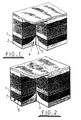
- this illustrates a series of strata incorporating a hydrocarbon bearing stratum 1 which lies over a water bearing stratum 2.
- a well 3 is drilled through the strata 1 and 2. Pressure within the hydrocarbon liquid and water is such that flow is established to the well 3.
- a "water cone" 4 is defined around the well 3 and as a result a conical interface 5 is established between the hydrocarbon liquid and water.
- the well 3 is lined with steel tubing down to the top of the strata 1, and the water cone reaches to adjacent the lined portion of the well, large volumes of water will be produced.
- Figure 2 illustrates the results of such an intervention.
- a branch well 6 is shown as being drilled into the stratum 1. Drilling such a branch 6 can substantially improve the proportion of produced liquids made up by hydrocarbon liquids. It is well known to form a branch such as the branch 6 of Figure 2 using coiled tubing drilling techniques. It is necessary however when using such techniques to maintain underbalanced conditions (that is maintain a positive pressure at the top of the well 3) in order to avoid drilling solids damaging the well. Such techniques have never been used offshore because the volume of material generated can only be handled in large installations.
- Figure 3 illustrates a shuttle tanker embodying the present invention.
- Figure 3 is based on a drawing extracted from "First Olsen Tankers" and shows a shuttle tanker of the type widely used in the North Sea.
- the only modification made to the standard shuttle tanker is the mounting of a superstructure 7 above the main deck of the tanker, for example at a height of approximately 3m so as to clear the installed deck pipes and vents.
- On that superstructure all the equipment necessary for direct well intervention is mounted, including a crane 8.
- the detailed layout of the equipment mounted on the superstructure 7 of Figure 3 is shown in Figure 4.
- a skid deck 9 is centrally mounted on the superstructure 7 adjacent a gantry crane 10.
- Coiled tubing drilling equipment 11 of conventional form is mounted adjacent the gantry crane 10.
- a separator assembly 12 and ancillary drilling support equipment assembly 13 are also mounted on the superstructure 7. All other equipment relied upon to achieve the required direct well intervention is also mounted on the superstructure 7.
- the separator assembly 12 is coupled to an appropriately positioned flare stack, for example at the stem of the vessel (not shown) and to the storage tanks of the tanker so as to enable produced hydrocarbon fluids to be stored for subsequent transport.
- the tanker In use, the tanker is dynamically positioned adjacent a subsea well riser.
- the skid deck 9 is then moved to an outboard position (not shown) over the riser to enable the coiled tubing equipment 11 to be coupled to the riser.
- Appropriate interventions can then be made via the riser and in particular coiled tubing drilling can be conducted in a manner which produces a multiphase mixture that is subsequently separated into its different phases in the separator assembly 12.
- the system described with reference to Figures 3 and 4 represents a breakthrough in offshore drilling, testing, waste disposal and well maintenance.
- the tanker cargo holds can be used for the collection of produced oil during underbalanced drilling.
- the system can give direct access to test subsea wells for extended durations.
- the system can be used for an extended water injection test and also allows for the disposal of waste into a subsea well.
- Existing systems in contrast cannot perform coiled tubing drilling and cannot collect produced oil, requiring a separate shuttle tanker in the event that oil is being produced during drilling.
- the vessel can still be employed in the charter market when not being used for direct well interventions.
- the invention offers a solution to the problem of achieving direct well interventions with coiled tubing drilling without the major costs associated with building and operating specialist vessels.
- a standard North Sea specified shuttle tanker with dynamic positioning can be readily chartered and fitted with a new deck above the installed deck pipes and vents. On that deck appropriate equipment can be installed such as:
- Coiled tubing drilling solutions include a cost-effective bottom assembly for standard mud systems and a wireline-based bottom hole assembly that fully exploits the benefits of through-tubing drilling, including use of foam and air systems.
- the present invention allows onshore underbalanced drilling technology to be transferred offshore without requiring extended equipment development. It also permits the production of significant volumes of hydrocarbons without requiring additional storage vessels, thereby reducing demands on cash flow whilst simultaneously avoiding damage to a well as a result of drilling operations.
- the motion characteristics of a relatively large shuttle tanker are more suited for delicate underbalanced drilling operations then the available relatively smaller and more buoyant alternative vessels.
- the invention also allows wells to be properly cleaned after interventions, thereby avoiding polluting the sometimes sensitive production system. Drilling waste can be managed in an optimal fashion, and all this can be achieved in relative safety given the large deck space available. All of these advantages are unavailable if using either a conventional semi-submersible vessel or a conventional purpose-built well intervention vessel.
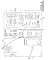
- two moon pools 13 and 14 extend vertically through the structure of a modified shuttle tanker.
- Three cranes 15, 16 and 17 can extend over the moon pools and areas indicating cargo manifolds 18, a derrick module 19, and a lay down area 20.
- Area 21 houses gas compression and process units, area 22 a flare boom, area 23 a flare knock-out drum skid, and area 24 a further lay down area served by a crane 25.
Description
- The present invention relates to a subsea well intervention vessel.
- Hydrocarbon production wells are established by using a rotating drill assembly. A rotating drill assembly is driven from the surface, generally in the case of a subsea well from a rig mounted on a platform positioned over the well. The platform can be mounted on the seabed or may be a semi-submersible assembly the location of which can be maintained in all but the most extreme conditions. After completion of drilling, the well is lined with tubing to enable hydrocarbon liquids to flow through the tubing from any hydrocarbon reserve into which the tubing extends. In some formations, hydrocarbon fluids and water occupy the same reservoir, the hydrocarbon fluids forming a layer on top of the water. If the production tubing of a well penetrates the formation initially occupied by the hydrocarbon fluids, as fluid flows to the well tubing the phenomenon known as "water coning" can occur, that is the interface between the hydrocarbon liquids and water slopes upwards towards the well. This effect results from pressure gradients established within the reservoir formation as a result of fluid flow through the formation to the well tubing. If the tip of the cone-shaped interface reaches the well tubing, large volumes of water will enter the well tubing, reducing the rate of hydrocarbon liquid production and increasing the costs of separating the produced hydrocarbon fluids from the water.
- In wells where water coning has become a problem, it is known to conduct further drilling operations so as to prevent or minimise water cone generation. For example, a bottom hole drilling assembly can be used to drill lateral passageways into the hydrocarbon liquid-bearing formation. This can be achieved by using conventional drilling techniques, but such techniques demand the shutting down of the well and often require the removal of the tubing lining the well. This involves substantial costs and risks. In addition, the hydrocarbon liquid bearing formation can be damaged by drilling fluids required for the additional drilling operations.
- In order to avoid the possibility of loss or damage to a well resulting from drilling interventions, an advanced drilling technology has been developed which allows technically difficult drilling to be achieved without substantial risk of damage to the formation. The technique is referred to as "underbalanced" drilling. With underbalanced drilling, the well is live (positive pressure at the surface) at all times. This can be achieved by either using a lightweight drilling fluid or relying upon gas lift control using a purpose-built blow out preventer assembly. A clean drilling fluid is pumped down the well, and this mixes with the formation fluids that are allowed to flow up the well, that flow transporting the rock cuttings to the surface. The five phases (gas, oil, formation water, drilling fluid and drilling solids) are then separated. On land this is a straightforward process as space is not at a premium. The equipment however is large and has not been thought suited for offshore operations.
- Underbalanced drilling can be conducted using either conventional rotary drilling or coiled tubing drilling. In the UK sector of the North Sea four wells have been drilled using underbalanced rotary drilling but this has only been possible using relatively large fixed (seabed-supported) platforms. On land, coiled tubing drilling has been used. In these known applications, a long seamless pipe which is stored on a drum is pushed into the well by an injector against the live well pressure. A turbine drill is mounted on the bottom end of the pipe and hydraulic pressure is delivered to the turbine drill through the pipe. This drives the turbine and permits drilling to take place. The small diameter of the pipe (typically 1 to 2 7/8") makes it possible for the pipe to pass through existing well-lining tubing (normally referred to as completions) so that it is not necessary to incur the substantial costs and risks of removing such tubing.
- Light intervention vessels are available which make it possible to conduct operations such as well servicing, e.g. well logging and general maintenance. Such vessels however cannot be considered appropriate platforms for interventions requiring drilling as they are not sufficiently stable for such operations and furthermore could not operate underbalanced drilling as they are too small to handle the volumes of material that result in such drilling. Furthermore, light intervention vessels require large capital investments as compared with the returns that can be generated, particularly as they are highly vulnerable to bad weather such that intervention costs are relatively high and utilisation time is relatively low. It would of course be possible to use a semi-submersible for well interventions but semi-submersibles cannot be used as yet for underbalanced drilling. Even such an approach would require support vessels to receive the produced liquids and solids.
- WO9949172 describes an offshore drilling system where a subsea well is drilled from a dynamically positionable tanker using a rotating drill.
- Nakagawa "Application of aerated-fluid drilling in deepwater" SPE, no. 52787, 9-11 November 1999, pages 1 to 6, XP 002167680 Amsterdam discusses an offshore well which is drilled using aerated fluid technology. However, Nakagawa acknowledges that operation of the system is not underbalanced.
- Accordingly no attempts have been made to use underbalanced coiled tubing drilling from floating units.
- It is an object of the present invention to provide a subsea well intervention vessel capable of re-entering existing production wells in a manner which allows well interventions to be performed without removing the well from its production mode and without polluting the subsea production system with well intervention effluent, e.g. drilling solids.
- According to the present invention, there is provided a subsea well intervention vessel comprising a dynamically positionable tanker and direct well intervention equipment mounted on the deck of the tanker, the direct well intervention equipment including equipment for underbalanced non-rotating drilling and hydrocarbon liquid separation coupled to storage tanks of the tanker such that separated hydrocarbon liquids can be stored in the tanker.
- The invention also provides a method for conducting off-shore underbalanced drilling, wherein a tanker having direct well intervention equipment mounted on its deck is dynamically positioned over a riser extending from a subsea well, the well intervention equipment is coupled to the riser, and underbalanced non-rotating drilling is performed, the resultant multi-phase mixture being separated on the tanker and separated hydrocarbon liquids being stored in storage tanks of the tanker.
- The term "non-rotating drilling" is used herein to include any drilling in which there is no rotation of the drill string including but not limited to underbalanced drilling using a rotary drill head powered through a non-rotating drill string.
- The well intervention equipment may be mounted on a superstructure above the main deck of a conventional shuttle tanker. Coiled tubing equipment may be mounted adjacent a skid deck which may be displaced to an outboard position over a well riser to which the coiled tubing equipment is to be connected. Thus a well intervention can be achieved by dynamically positioning the shuttle tanker adjacent a well riser, moving the skid deck to the outboard position, coupling the coiled tubing equipment to the riser, and performing the necessary interventions in the well to which the riser is connected, fluids and solids produced during the coiled tubing drilling process being separated by equipment mounted on the superstructure and hydrocarbon liquids being transferred from the separation equipment to the shuttle tanker storage hold.
- As an alternative to providing a skid deck displaceable to an outboard position, the drilling equipment could be mounted adjacent a moon pool extending through the tanker deck.
- Embodiments of the present invention will now be described, by way of example, with reference to the accompanying drawings, in which:
- Figure 1 is a schematic representation taken from an available document showing the phenomenon of water coning;
- Figure 2 is a further illustration taken from a published document showing the results of coiled tubing drilling in the structure of Figure 1 so as to improve the rate of production of hydrocarbon liquids;
- Figure 3 is a side view of a known North Sea shuttle tanker incorporating direct well intervention equipment in accordance with the present invention;
- Figure 4 is a schematic layout diagram of the direct well intervention equipment shown in side view in Figure 3; and
- Figure 5 is a schematic illustration of a tanker which defines moon pools through which coiled tubing drilling can be performed;
-
- Referring to Figure 1, this illustrates a series of strata incorporating a hydrocarbon bearing stratum 1 which lies over a water bearing stratum 2. A
well 3 is drilled through the strata 1 and 2. Pressure within the hydrocarbon liquid and water is such that flow is established to thewell 3. As a result of that flow a "water cone" 4 is defined around thewell 3 and as a result aconical interface 5 is established between the hydrocarbon liquid and water. If thewell 3 is lined with steel tubing down to the top of the strata 1, and the water cone reaches to adjacent the lined portion of the well, large volumes of water will be produced. Clearly this is highly disadvantageous and therefore it is known to intervene in wells which suffer from the water coning effect. Figure 2 illustrates the results of such an intervention. - Referring to Figure 2, a
branch well 6 is shown as being drilled into the stratum 1. Drilling such abranch 6 can substantially improve the proportion of produced liquids made up by hydrocarbon liquids. It is well known to form a branch such as thebranch 6 of Figure 2 using coiled tubing drilling techniques. It is necessary however when using such techniques to maintain underbalanced conditions (that is maintain a positive pressure at the top of the well 3) in order to avoid drilling solids damaging the well. Such techniques have never been used offshore because the volume of material generated can only be handled in large installations. - Figure 3 illustrates a shuttle tanker embodying the present invention. Figure 3 is based on a drawing extracted from "First Olsen Tankers" and shows a shuttle tanker of the type widely used in the North Sea. The only modification made to the standard shuttle tanker is the mounting of a
superstructure 7 above the main deck of the tanker, for example at a height of approximately 3m so as to clear the installed deck pipes and vents. On that superstructure all the equipment necessary for direct well intervention is mounted, including acrane 8. The detailed layout of the equipment mounted on thesuperstructure 7 of Figure 3 is shown in Figure 4. - Referring to Figure 4, a
skid deck 9 is centrally mounted on thesuperstructure 7 adjacent agantry crane 10. Coiledtubing drilling equipment 11 of conventional form is mounted adjacent thegantry crane 10. Aseparator assembly 12 and ancillary drillingsupport equipment assembly 13 are also mounted on thesuperstructure 7. All other equipment relied upon to achieve the required direct well intervention is also mounted on thesuperstructure 7. Theseparator assembly 12 is coupled to an appropriately positioned flare stack, for example at the stem of the vessel (not shown) and to the storage tanks of the tanker so as to enable produced hydrocarbon fluids to be stored for subsequent transport. - In use, the tanker is dynamically positioned adjacent a subsea well riser. The
skid deck 9 is then moved to an outboard position (not shown) over the riser to enable the coiledtubing equipment 11 to be coupled to the riser. Appropriate interventions can then be made via the riser and in particular coiled tubing drilling can be conducted in a manner which produces a multiphase mixture that is subsequently separated into its different phases in theseparator assembly 12. - The system described with reference to Figures 3 and 4 represents a breakthrough in offshore drilling, testing, waste disposal and well maintenance. The tanker cargo holds can be used for the collection of produced oil during underbalanced drilling. The system can give direct access to test subsea wells for extended durations. The system can be used for an extended water injection test and also allows for the disposal of waste into a subsea well. Existing systems in contrast cannot perform coiled tubing drilling and cannot collect produced oil, requiring a separate shuttle tanker in the event that oil is being produced during drilling.
- Furthermore the original features of the shuttle tanker are maintained and therefore the vessel can still be employed in the charter market when not being used for direct well interventions. As a result the invention offers a solution to the problem of achieving direct well interventions with coiled tubing drilling without the major costs associated with building and operating specialist vessels.
- A standard North Sea specified shuttle tanker with dynamic positioning can be readily chartered and fitted with a new deck above the installed deck pipes and vents. On that deck appropriate equipment can be installed such as:
- A skid mounted derrick riser handling unit with subsea control panel;
- Stumps for the subsea well intervention equipment;
- A pipe rack;
- Coiled tubing reels, control unit and power pack;
- Cementing unit and blender;
- Production test equipment including choke manifold, heater treater, separators, degassing boot and gas flare;
- Tanks for kill mud;
- A closed circulation system for handling drilling mud and drilled solids during underbalanced drilling;
- Storage tanks for chemical and solid wastes;
- Craneage for subsea equipment and supplies;
- Remote controlled vehicles for working and observation tasks;
- Water supplies for cooling and fire fighting services;
-
- It is probably the case that there are of the order of 2000 subsea completions currently operative. With the present invention, such completions could be made accessible for of the order of 100,000 US dollars per day in contrast with currently quoted costs of the order of 200,000 to 300,000 US dollars per day. Thus the invention dramatically affects the technical capability of the offshore industry in the context of the financial constraints which face that industry.
- Coiled tubing drilling solutions include a cost-effective bottom assembly for standard mud systems and a wireline-based bottom hole assembly that fully exploits the benefits of through-tubing drilling, including use of foam and air systems. The present invention allows onshore underbalanced drilling technology to be transferred offshore without requiring extended equipment development. It also permits the production of significant volumes of hydrocarbons without requiring additional storage vessels, thereby reducing demands on cash flow whilst simultaneously avoiding damage to a well as a result of drilling operations. The motion characteristics of a relatively large shuttle tanker are more suited for delicate underbalanced drilling operations then the available relatively smaller and more buoyant alternative vessels. This extends the amount of time that weather permits operation and reduces fatigue stress on the coiled tubing where it is fed from the tanker to the subsea well riser. The invention also allows wells to be properly cleaned after interventions, thereby avoiding polluting the sometimes sensitive production system. Drilling waste can be managed in an optimal fashion, and all this can be achieved in relative safety given the large deck space available. All of these advantages are unavailable if using either a conventional semi-submersible vessel or a conventional purpose-built well intervention vessel.
- In the embodiment of the invention described with reference to Figures 3 and 4, components necessary for the operation of the invention are mounted on a skid deck which can be moved to an outboard position. In an alternative arrangement illustrated in Figure 5, such components are mounted adjacent moon pools extending through the structure of an otherwise conventional tanker.
- Referring to Figure 5, two
moon pools 13 and 14 extend vertically through the structure of a modified shuttle tanker. Threecranes crane 25. - Taking a standard double hull shuttle tanker, the modifications required to produce the vessel schematically illustrated in Figure 5 which can function in accordance with the present invention would be an upgrade of the dynamic positioning capability, installation of a first moon pool (8m2) for intervention work, installation of a second moon pool (4m2) for remotely operated vehicle work, mounting of cranes, process equipment and lay down areas for deck-mounted equipment, and the mounting of flare facilities and associated utilities.
Claims (5)
- A subsea well intervention vessel comprising a dynamically positionable tanker and direct well intervention equipment (11) mounted on a deck (7) of the tanker, characterised in that the direct well intervention equipment (11) includes equipment for underbalanced non-rotating drilling and hydrocarbon liquid separation (12) coupled to storage tanks of the tanker such that separated hydrocarbon liquids can be stored in the tanker.
- A vessel according to claim 1, wherein the well intervention equipment (11) is mounted on a superstructure (7) above the main deck of a shuttle tanker.
- A vessel according to claim 1 or 2, wherein coiled tubing drilling equipment (11) is mounted adjacent a skid deck (9) which may be displaced to an outboard position over a well riser to which the coiled tubing drilling equipment (11) is to be connected.
- A vessel according claim 1 or 2, wherein coiled tubing drilling equipment (11) is mounted adjacent a moon pool (13, 14) located over a well riser to which the coiled tubing drilling equipment is to be connected.
- A method for conducting off-shore underbalanced drilling, wherein a tanker having direct well intervention equipment (11) mounted on its deck is dynamically positioned over a riser extending from a subsea well (3), characterised in that the well intervention equipment (11) is coupled to the riser, and underbalanced non-rotating drilling is performed, the resultant multi-phase mixture being separated on the tanker and separated hydrocarbon liquids being stored in storage tanks of the tanker.
Applications Claiming Priority (3)
| Application Number | Priority Date | Filing Date | Title |
|---|---|---|---|
| GB9930450 | 1999-12-23 | ||
| GBGB9930450.3A GB9930450D0 (en) | 1999-12-23 | 1999-12-23 | Subsea well intervention vessel |
| PCT/GB2000/004899 WO2001048351A2 (en) | 1999-12-23 | 2000-12-20 | Subsea well intervention vessel |
Publications (2)
| Publication Number | Publication Date |
|---|---|
| EP1240404A2 EP1240404A2 (en) | 2002-09-18 |
| EP1240404B1 true EP1240404B1 (en) | 2003-12-03 |
Family
ID=10866905
Family Applications (1)
| Application Number | Title | Priority Date | Filing Date |
|---|---|---|---|
| EP00985640A Expired - Lifetime EP1240404B1 (en) | 1999-12-23 | 2000-12-20 | Subsea well intervention vessel |
Country Status (24)
| Country | Link |
|---|---|
| US (1) | US6840322B2 (en) |
| EP (1) | EP1240404B1 (en) |
| JP (1) | JP2003518576A (en) |
| KR (1) | KR100799958B1 (en) |
| CN (1) | CN1228534C (en) |
| AP (1) | AP1370A (en) |
| AT (1) | ATE255674T1 (en) |
| AU (1) | AU779937B2 (en) |
| BR (1) | BR0016527B1 (en) |
| CA (1) | CA2392331C (en) |
| DE (1) | DE60006998T2 (en) |
| DK (1) | DK1240404T3 (en) |
| ES (1) | ES2211656T3 (en) |
| GB (2) | GB9930450D0 (en) |
| HK (1) | HK1047611B (en) |
| MX (1) | MXPA02006375A (en) |
| NO (1) | NO327209B1 (en) |
| NZ (1) | NZ518885A (en) |
| OA (1) | OA12127A (en) |
| PT (1) | PT1240404E (en) |
| RU (1) | RU2257456C2 (en) |
| TR (1) | TR200400337T4 (en) |
| WO (1) | WO2001048351A2 (en) |
| ZA (1) | ZA200203763B (en) |
Cited By (8)
| Publication number | Priority date | Publication date | Assignee | Title |
|---|---|---|---|---|
| US8201628B2 (en) | 2010-04-27 | 2012-06-19 | Halliburton Energy Services, Inc. | Wellbore pressure control with segregated fluid columns |
| US8281875B2 (en) | 2008-12-19 | 2012-10-09 | Halliburton Energy Services, Inc. | Pressure and flow control in drilling operations |
| US8776894B2 (en) | 2006-11-07 | 2014-07-15 | Halliburton Energy Services, Inc. | Offshore universal riser system |
| US8820405B2 (en) | 2010-04-27 | 2014-09-02 | Halliburton Energy Services, Inc. | Segregating flowable materials in a well |
| US8833488B2 (en) | 2011-04-08 | 2014-09-16 | Halliburton Energy Services, Inc. | Automatic standpipe pressure control in drilling |
| US9080407B2 (en) | 2011-05-09 | 2015-07-14 | Halliburton Energy Services, Inc. | Pressure and flow control in drilling operations |
| US9249638B2 (en) | 2011-04-08 | 2016-02-02 | Halliburton Energy Services, Inc. | Wellbore pressure control with optimized pressure drilling |
| US9605507B2 (en) | 2011-09-08 | 2017-03-28 | Halliburton Energy Services, Inc. | High temperature drilling with lower temperature rated tools |
Families Citing this family (51)
| Publication number | Priority date | Publication date | Assignee | Title |
|---|---|---|---|---|
| US7100710B2 (en) * | 1994-10-14 | 2006-09-05 | Weatherford/Lamb, Inc. | Methods and apparatus for cementing drill strings in place for one pass drilling and completion of oil and gas wells |
| US6868906B1 (en) * | 1994-10-14 | 2005-03-22 | Weatherford/Lamb, Inc. | Closed-loop conveyance systems for well servicing |
| US7108084B2 (en) * | 1994-10-14 | 2006-09-19 | Weatherford/Lamb, Inc. | Methods and apparatus for cementing drill strings in place for one pass drilling and completion of oil and gas wells |
| US7228901B2 (en) * | 1994-10-14 | 2007-06-12 | Weatherford/Lamb, Inc. | Method and apparatus for cementing drill strings in place for one pass drilling and completion of oil and gas wells |
| US7013997B2 (en) * | 1994-10-14 | 2006-03-21 | Weatherford/Lamb, Inc. | Methods and apparatus for cementing drill strings in place for one pass drilling and completion of oil and gas wells |
| US6742596B2 (en) * | 2001-05-17 | 2004-06-01 | Weatherford/Lamb, Inc. | Apparatus and methods for tubular makeup interlock |
| US6536520B1 (en) | 2000-04-17 | 2003-03-25 | Weatherford/Lamb, Inc. | Top drive casing system |
| US7509722B2 (en) * | 1997-09-02 | 2009-03-31 | Weatherford/Lamb, Inc. | Positioning and spinning device |
| GB9815809D0 (en) * | 1998-07-22 | 1998-09-16 | Appleton Robert P | Casing running tool |
| GB2340857A (en) * | 1998-08-24 | 2000-03-01 | Weatherford Lamb | An apparatus for facilitating the connection of tubulars and alignment with a top drive |
| US7188687B2 (en) * | 1998-12-22 | 2007-03-13 | Weatherford/Lamb, Inc. | Downhole filter |
| CA2356194C (en) * | 1998-12-22 | 2007-02-27 | Weatherford/Lamb, Inc. | Procedures and equipment for profiling and jointing of pipes |
| GB2345074A (en) * | 1998-12-24 | 2000-06-28 | Weatherford Lamb | Floating joint to facilitate the connection of tubulars using a top drive |
| GB2347441B (en) * | 1998-12-24 | 2003-03-05 | Weatherford Lamb | Apparatus and method for facilitating the connection of tubulars using a top drive |
| US6896075B2 (en) * | 2002-10-11 | 2005-05-24 | Weatherford/Lamb, Inc. | Apparatus and methods for drilling with casing |
| US7311148B2 (en) * | 1999-02-25 | 2007-12-25 | Weatherford/Lamb, Inc. | Methods and apparatus for wellbore construction and completion |
| CA2393754C (en) * | 1999-12-22 | 2009-10-20 | Weatherford/Lamb, Inc. | Drilling bit for drilling while running casing |
| US7334650B2 (en) * | 2000-04-13 | 2008-02-26 | Weatherford/Lamb, Inc. | Apparatus and methods for drilling a wellbore using casing |
| US7325610B2 (en) * | 2000-04-17 | 2008-02-05 | Weatherford/Lamb, Inc. | Methods and apparatus for handling and drilling with tubulars or casing |
| AU2003228214B2 (en) * | 2002-02-19 | 2007-11-22 | Varco I/P, Inc. | Subsea intervention system, method and components thereof |
| GB0206227D0 (en) * | 2002-03-16 | 2002-05-01 | Weatherford Lamb | Bore-lining and drilling |
| US6994176B2 (en) * | 2002-07-29 | 2006-02-07 | Weatherford/Lamb, Inc. | Adjustable rotating guides for spider or elevator |
| US6899186B2 (en) * | 2002-12-13 | 2005-05-31 | Weatherford/Lamb, Inc. | Apparatus and method of drilling with casing |
| US7303022B2 (en) * | 2002-10-11 | 2007-12-04 | Weatherford/Lamb, Inc. | Wired casing |
| US6968902B2 (en) * | 2002-11-12 | 2005-11-29 | Vetco Gray Inc. | Drilling and producing deep water subsea wells |
| US7380589B2 (en) * | 2002-12-13 | 2008-06-03 | Varco Shaffer, Inc. | Subsea coiled tubing injector with pressure compensation |
| USRE42877E1 (en) | 2003-02-07 | 2011-11-01 | Weatherford/Lamb, Inc. | Methods and apparatus for wellbore construction and completion |
| US7874352B2 (en) | 2003-03-05 | 2011-01-25 | Weatherford/Lamb, Inc. | Apparatus for gripping a tubular on a drilling rig |
| GB2416360B (en) * | 2003-03-05 | 2007-08-22 | Weatherford Lamb | Drilling with casing latch |
| GB2439427B (en) * | 2003-03-05 | 2008-02-13 | Weatherford Lamb | Casing running and drilling system |
| US7503397B2 (en) * | 2004-07-30 | 2009-03-17 | Weatherford/Lamb, Inc. | Apparatus and methods of setting and retrieving casing with drilling latch and bottom hole assembly |
| WO2004079147A2 (en) * | 2003-03-05 | 2004-09-16 | Weatherford/Lamb, Inc. | Method and apparatus for drilling with casing |
| US7370707B2 (en) * | 2003-04-04 | 2008-05-13 | Weatherford/Lamb, Inc. | Method and apparatus for handling wellbore tubulars |
| GB2436497B8 (en) | 2003-04-10 | 2007-12-17 | Vik Sandvik As | Method for loading/unloading a support vessel at an offshore installation. |
| US7650944B1 (en) * | 2003-07-11 | 2010-01-26 | Weatherford/Lamb, Inc. | Vessel for well intervention |
| US7264067B2 (en) * | 2003-10-03 | 2007-09-04 | Weatherford/Lamb, Inc. | Method of drilling and completing multiple wellbores inside a single caisson |
| NO329611B1 (en) * | 2004-07-20 | 2010-11-22 | Weatherford Lamb | Feeding Mater. |
| CA2532907C (en) * | 2005-01-12 | 2008-08-12 | Weatherford/Lamb, Inc. | One-position fill-up and circulating tool |
| CA2533115C (en) * | 2005-01-18 | 2010-06-08 | Weatherford/Lamb, Inc. | Top drive torque booster |
| US7225877B2 (en) * | 2005-04-05 | 2007-06-05 | Varco I/P, Inc. | Subsea intervention fluid transfer system |
| GB2437526A (en) * | 2006-04-27 | 2007-10-31 | Multi Operational Service Tank | A sub-sea well intervention vessel and method |
| GB2437647B (en) * | 2006-04-27 | 2011-02-09 | Weatherford Lamb | Torque sub for use with top drive |
| US7882902B2 (en) * | 2006-11-17 | 2011-02-08 | Weatherford/Lamb, Inc. | Top drive interlock |
| US7628224B2 (en) * | 2007-04-30 | 2009-12-08 | Kellogg Brown & Root Llc | Shallow/intermediate water multipurpose floating platform for arctic environments |
| US20090199591A1 (en) * | 2008-02-11 | 2009-08-13 | Daewoo Shipbuilding & Marine Engineering Co., Ltd. | Liquefied natural gas with butane and method of storing and processing the same |
| US9567843B2 (en) * | 2009-07-30 | 2017-02-14 | Halliburton Energy Services, Inc. | Well drilling methods with event detection |
| WO2016201531A1 (en) * | 2015-06-18 | 2016-12-22 | Petróleo Brasileiro S.A. - Petrobras | Intervention and installation system for at least one production flow and elevation device inside at least one production riser in a floating production unit |
| CN105216975A (en) * | 2015-10-19 | 2016-01-06 | 宏华海洋油气装备(江苏)有限公司 | Carry the workover platform of thrust power position fixing system |
| US20180257752A1 (en) * | 2017-03-08 | 2018-09-13 | Zentech, Inc. | Dynamically positioned liquid mud plant vessel |
| US11794893B2 (en) | 2020-09-08 | 2023-10-24 | Frederick William MacDougall | Transportation system for transporting organic payloads |
| CA3191564A1 (en) | 2020-09-08 | 2022-03-17 | Frederick William Macdougall | Coalification and carbon sequestration using deep ocean hydrothermal borehole vents |
Family Cites Families (24)
| Publication number | Priority date | Publication date | Assignee | Title |
|---|---|---|---|---|
| US3802209A (en) * | 1972-09-25 | 1974-04-09 | C Weaver | Self-contained drill ship |
| US4448568A (en) * | 1982-06-22 | 1984-05-15 | Mobil Oil Corporation | Marine surface facility work station for subsea equipment handling |
| GB8415143D0 (en) * | 1984-06-14 | 1984-07-18 | Douglas C P | Processing drilling fluid |
| US4566544A (en) * | 1984-10-29 | 1986-01-28 | Schlumberger Technology Corporation | Firing system for tubing conveyed perforating gun |
| JPH0724078B2 (en) * | 1986-02-14 | 1995-03-15 | カシオ計算機株式会社 | Sales data processing device |
| JP2830266B2 (en) * | 1990-01-16 | 1998-12-02 | 石川島播磨重工業株式会社 | Crude oil storage and unloading equipment |
| NO311075B1 (en) * | 1994-02-02 | 2001-10-08 | Norske Stats Oljeselskap | Vessels that can alternate between operating as a production vessel for hydrocarbon production / storage vessels on offshore fields and as shuttle tanks |
| NO305138B1 (en) * | 1994-10-31 | 1999-04-06 | Mercur Slimhole Drilling And I | Device for use in drilling oil / gas wells |
| US5720356A (en) * | 1996-02-01 | 1998-02-24 | Gardes; Robert | Method and system for drilling underbalanced radial wells utilizing a dual string technique in a live well |
| US6085851A (en) * | 1996-05-03 | 2000-07-11 | Transocean Offshore Inc. | Multi-activity offshore exploration and/or development drill method and apparatus |
| JPH10169351A (en) * | 1996-12-13 | 1998-06-23 | Nippon Kaiyo Kutsusaku Kk | Excavation method of submarine well and installation method of observation instrument in submarine well |
| US6019174A (en) * | 1997-01-16 | 2000-02-01 | Korsgaard; Jens | Method and apparatus for producing and shipping hydrocarbons offshore |
| US5873420A (en) * | 1997-05-27 | 1999-02-23 | Gearhart; Marvin | Air and mud control system for underbalanced drilling |
| US6273193B1 (en) * | 1997-12-16 | 2001-08-14 | Transocean Sedco Forex, Inc. | Dynamically positioned, concentric riser, drilling method and apparatus |
| US6325159B1 (en) * | 1998-03-27 | 2001-12-04 | Hydril Company | Offshore drilling system |
| JP2992935B2 (en) * | 1998-05-19 | 1999-12-20 | 石油公団 | Ship-type floating oil production system |
| US6415877B1 (en) * | 1998-07-15 | 2002-07-09 | Deep Vision Llc | Subsea wellbore drilling system for reducing bottom hole pressure |
| US6234258B1 (en) * | 1999-03-08 | 2001-05-22 | Halliburton Energy Services, Inc. | Methods of separation of materials in an under-balanced drilling operation |
| US6328107B1 (en) * | 1999-09-17 | 2001-12-11 | Exxonmobil Upstream Research Company | Method for installing a well casing into a subsea well being drilled with a dual density drilling system |
| US6450262B1 (en) * | 1999-12-09 | 2002-09-17 | Stewart & Stevenson Services, Inc. | Riser isolation tool |
| US6367402B1 (en) * | 2000-04-04 | 2002-04-09 | J. Ray Mcdermott, S.A. | Multi-use construction vessel |
| US6453838B1 (en) * | 2000-10-20 | 2002-09-24 | Ocean Production Technology, Llc | Turret-less floating production ship |
| US6474422B2 (en) * | 2000-12-06 | 2002-11-05 | Texas A&M University System | Method for controlling a well in a subsea mudlift drilling system |
| US6536540B2 (en) * | 2001-02-15 | 2003-03-25 | De Boer Luc | Method and apparatus for varying the density of drilling fluids in deep water oil drilling applications |
-
1999
- 1999-12-23 GB GBGB9930450.3A patent/GB9930450D0/en not_active Ceased
-
2000
- 2000-12-20 AT AT00985640T patent/ATE255674T1/en not_active IP Right Cessation
- 2000-12-20 CA CA002392331A patent/CA2392331C/en not_active Expired - Fee Related
- 2000-12-20 GB GB0208346A patent/GB2374048B/en not_active Revoked
- 2000-12-20 MX MXPA02006375A patent/MXPA02006375A/en active IP Right Grant
- 2000-12-20 DK DK00985640T patent/DK1240404T3/en active
- 2000-12-20 AP APAP/P/2002/002527A patent/AP1370A/en active
- 2000-12-20 EP EP00985640A patent/EP1240404B1/en not_active Expired - Lifetime
- 2000-12-20 TR TR2004/00337T patent/TR200400337T4/en unknown
- 2000-12-20 ES ES00985640T patent/ES2211656T3/en not_active Expired - Lifetime
- 2000-12-20 BR BRPI0016527-1A patent/BR0016527B1/en not_active IP Right Cessation
- 2000-12-20 WO PCT/GB2000/004899 patent/WO2001048351A2/en active IP Right Grant
- 2000-12-20 RU RU2002113372/03A patent/RU2257456C2/en not_active IP Right Cessation
- 2000-12-20 AU AU22046/01A patent/AU779937B2/en not_active Ceased
- 2000-12-20 KR KR1020027008187A patent/KR100799958B1/en not_active IP Right Cessation
- 2000-12-20 OA OA1200200194A patent/OA12127A/en unknown
- 2000-12-20 NZ NZ518885A patent/NZ518885A/en unknown
- 2000-12-20 CN CNB008176566A patent/CN1228534C/en not_active Expired - Fee Related
- 2000-12-20 PT PT00985640T patent/PT1240404E/en unknown
- 2000-12-20 JP JP2001548839A patent/JP2003518576A/en active Pending
- 2000-12-20 DE DE60006998T patent/DE60006998T2/en not_active Expired - Fee Related
- 2000-12-20 US US10/149,951 patent/US6840322B2/en not_active Expired - Fee Related
-
2002
- 2002-05-10 ZA ZA200203763A patent/ZA200203763B/en unknown
- 2002-06-20 NO NO20022981A patent/NO327209B1/en not_active IP Right Cessation
- 2002-12-16 HK HK02109107.9A patent/HK1047611B/en not_active IP Right Cessation
Cited By (19)
| Publication number | Priority date | Publication date | Assignee | Title |
|---|---|---|---|---|
| US8887814B2 (en) | 2006-11-07 | 2014-11-18 | Halliburton Energy Services, Inc. | Offshore universal riser system |
| US9127511B2 (en) | 2006-11-07 | 2015-09-08 | Halliburton Energy Services, Inc. | Offshore universal riser system |
| US9051790B2 (en) | 2006-11-07 | 2015-06-09 | Halliburton Energy Services, Inc. | Offshore drilling method |
| US8776894B2 (en) | 2006-11-07 | 2014-07-15 | Halliburton Energy Services, Inc. | Offshore universal riser system |
| US9376870B2 (en) | 2006-11-07 | 2016-06-28 | Halliburton Energy Services, Inc. | Offshore universal riser system |
| US9157285B2 (en) | 2006-11-07 | 2015-10-13 | Halliburton Energy Services, Inc. | Offshore drilling method |
| US8881831B2 (en) | 2006-11-07 | 2014-11-11 | Halliburton Energy Services, Inc. | Offshore universal riser system |
| US9127512B2 (en) | 2006-11-07 | 2015-09-08 | Halliburton Energy Services, Inc. | Offshore drilling method |
| US9085940B2 (en) | 2006-11-07 | 2015-07-21 | Halliburton Energy Services, Inc. | Offshore universal riser system |
| US8281875B2 (en) | 2008-12-19 | 2012-10-09 | Halliburton Energy Services, Inc. | Pressure and flow control in drilling operations |
| US8286730B2 (en) | 2009-12-15 | 2012-10-16 | Halliburton Energy Services, Inc. | Pressure and flow control in drilling operations |
| US8820405B2 (en) | 2010-04-27 | 2014-09-02 | Halliburton Energy Services, Inc. | Segregating flowable materials in a well |
| US8261826B2 (en) | 2010-04-27 | 2012-09-11 | Halliburton Energy Services, Inc. | Wellbore pressure control with segregated fluid columns |
| US8201628B2 (en) | 2010-04-27 | 2012-06-19 | Halliburton Energy Services, Inc. | Wellbore pressure control with segregated fluid columns |
| US8833488B2 (en) | 2011-04-08 | 2014-09-16 | Halliburton Energy Services, Inc. | Automatic standpipe pressure control in drilling |
| US9249638B2 (en) | 2011-04-08 | 2016-02-02 | Halliburton Energy Services, Inc. | Wellbore pressure control with optimized pressure drilling |
| US9080407B2 (en) | 2011-05-09 | 2015-07-14 | Halliburton Energy Services, Inc. | Pressure and flow control in drilling operations |
| US9605507B2 (en) | 2011-09-08 | 2017-03-28 | Halliburton Energy Services, Inc. | High temperature drilling with lower temperature rated tools |
| US10233708B2 (en) | 2012-04-10 | 2019-03-19 | Halliburton Energy Services, Inc. | Pressure and flow control in drilling operations |
Also Published As
Similar Documents
| Publication | Publication Date | Title |
|---|---|---|
| EP1240404B1 (en) | Subsea well intervention vessel | |
| EP2185784B1 (en) | Return line mounted pump for riserless mud return system | |
| US3261398A (en) | Apparatus for producing underwater oil fields | |
| US20080267716A1 (en) | Shallow/intermediate water multipurpose floating platform for arctic environments | |
| US3292695A (en) | Method and apparatus for producing underwater oil fields | |
| US20100326667A1 (en) | Production of hydrocarbons | |
| BRPI0402753B1 (en) | Mechanism and method for intervention in oil pipelines and well drilling vessels | |
| NO327352B1 (en) | System and method for recovering return fluid from undersea wellbores | |
| NO20111073A1 (en) | Rigeless abandon system | |
| US20120037376A1 (en) | System and Method For Well Clean-Up | |
| Geiger et al. | Offshore vessels and their unique applications for the systems designer | |
| US7644768B2 (en) | Separation device for material from a drilling rig situated on the seabed | |
| WO2007108697A1 (en) | Sealed pipe coupling unit for a drilling rig device situated on the seabed | |
| NO851244L (en) | DEPTH WATER PRODUCTION CONSTRUCTION | |
| Ayling et al. | Seabed located drilling rig-ITF pioneer project | |
| Le Bouteiller et al. | Subsea Well Servicing: A New and Economical System—The SWIMS | |
| Formigli et al. | Ultra-Deepwater Offshore Brazil: Next Step To Achieve 3,000 Meters | |
| Cockrill | 3 Moored production and loading facilities as experienced at the Argyll Field | |
| Atteraas et al. | Underwater Technology: Offshore Petroleum | |
| NO20131567A1 (en) | underwater System |
Legal Events
| Date | Code | Title | Description |
|---|---|---|---|
| PUAI | Public reference made under article 153(3) epc to a published international application that has entered the european phase |
Free format text: ORIGINAL CODE: 0009012 |
|
| 17P | Request for examination filed |
Effective date: 20020530 |
|
| AK | Designated contracting states |
Kind code of ref document: A2 Designated state(s): AT BE CH CY DE DK ES FI FR GB GR IE IT LI LU MC NL PT SE TR |
|
| AX | Request for extension of the european patent |
Free format text: AL PAYMENT 20020530;LT PAYMENT 20020530;LV PAYMENT 20020530;MK;RO PAYMENT 20020530;SI |
|
| GRAH | Despatch of communication of intention to grant a patent |
Free format text: ORIGINAL CODE: EPIDOS IGRA |
|
| GRAS | Grant fee paid |
Free format text: ORIGINAL CODE: EPIDOSNIGR3 |
|
| GRAA | (expected) grant |
Free format text: ORIGINAL CODE: 0009210 |
|
| AK | Designated contracting states |
Kind code of ref document: B1 Designated state(s): AT BE CH CY DE DK ES FI FR GB GR IE IT LI LU MC NL PT SE TR |
|
| AX | Request for extension of the european patent |
Extension state: AL LT LV RO |
|
| PG25 | Lapsed in a contracting state [announced via postgrant information from national office to epo] |
Ref country code: AT Free format text: LAPSE BECAUSE OF FAILURE TO SUBMIT A TRANSLATION OF THE DESCRIPTION OR TO PAY THE FEE WITHIN THE PRESCRIBED TIME-LIMIT Effective date: 20031203 Ref country code: CH Free format text: LAPSE BECAUSE OF FAILURE TO SUBMIT A TRANSLATION OF THE DESCRIPTION OR TO PAY THE FEE WITHIN THE PRESCRIBED TIME-LIMIT Effective date: 20031203 Ref country code: LI Free format text: LAPSE BECAUSE OF FAILURE TO SUBMIT A TRANSLATION OF THE DESCRIPTION OR TO PAY THE FEE WITHIN THE PRESCRIBED TIME-LIMIT Effective date: 20031203 |
|
| REG | Reference to a national code |
Ref country code: GB Ref legal event code: FG4D |
|
| REG | Reference to a national code |
Ref country code: CH Ref legal event code: EP |
|
| PG25 | Lapsed in a contracting state [announced via postgrant information from national office to epo] |
Ref country code: CY Free format text: LAPSE BECAUSE OF FAILURE TO SUBMIT A TRANSLATION OF THE DESCRIPTION OR TO PAY THE FEE WITHIN THE PRESCRIBED TIME-LIMIT Effective date: 20031220 Ref country code: LU Free format text: LAPSE BECAUSE OF NON-PAYMENT OF DUE FEES Effective date: 20031220 |
|
| PG25 | Lapsed in a contracting state [announced via postgrant information from national office to epo] |
Ref country code: MC Free format text: LAPSE BECAUSE OF NON-PAYMENT OF DUE FEES Effective date: 20031231 |
|
| REG | Reference to a national code |
Ref country code: IE Ref legal event code: FG4D |
|
| REF | Corresponds to: |
Ref document number: 60006998 Country of ref document: DE Date of ref document: 20040115 Kind code of ref document: P |
|
| REG | Reference to a national code |
Ref country code: SE Ref legal event code: TRGR |
|
| REG | Reference to a national code |
Ref country code: DK Ref legal event code: T3 |
|
| REG | Reference to a national code |
Ref country code: GR Ref legal event code: EP Ref document number: 20040400744 Country of ref document: GR |
|
| REG | Reference to a national code |
Ref country code: PT Ref legal event code: SC4A Free format text: AVAILABILITY OF NATIONAL TRANSLATION Effective date: 20040223 |
|
| REG | Reference to a national code |
Ref country code: CH Ref legal event code: PL |
|
| REG | Reference to a national code |
Ref country code: ES Ref legal event code: FG2A Ref document number: 2211656 Country of ref document: ES Kind code of ref document: T3 |
|
| REG | Reference to a national code |
Ref country code: HK Ref legal event code: GR Ref document number: 1047611 Country of ref document: HK |
|
| ET | Fr: translation filed | ||
| PLBE | No opposition filed within time limit |
Free format text: ORIGINAL CODE: 0009261 |
|
| STAA | Information on the status of an ep patent application or granted ep patent |
Free format text: STATUS: NO OPPOSITION FILED WITHIN TIME LIMIT |
|
| 26N | No opposition filed |
Effective date: 20040906 |
|
| PGFP | Annual fee paid to national office [announced via postgrant information from national office to epo] |
Ref country code: CY Payment date: 20041220 Year of fee payment: 5 |
|
| PGFP | Annual fee paid to national office [announced via postgrant information from national office to epo] |
Ref country code: NL Payment date: 20051204 Year of fee payment: 6 |
|
| PGFP | Annual fee paid to national office [announced via postgrant information from national office to epo] |
Ref country code: FR Payment date: 20051208 Year of fee payment: 6 |
|
| PGFP | Annual fee paid to national office [announced via postgrant information from national office to epo] |
Ref country code: GR Payment date: 20051213 Year of fee payment: 6 |
|
| PGFP | Annual fee paid to national office [announced via postgrant information from national office to epo] |
Ref country code: FI Payment date: 20051214 Year of fee payment: 6 |
|
| PGFP | Annual fee paid to national office [announced via postgrant information from national office to epo] |
Ref country code: DE Payment date: 20051215 Year of fee payment: 6 Ref country code: DK Payment date: 20051215 Year of fee payment: 6 |
|
| PGFP | Annual fee paid to national office [announced via postgrant information from national office to epo] |
Ref country code: PT Payment date: 20051227 Year of fee payment: 6 |
|
| PGFP | Annual fee paid to national office [announced via postgrant information from national office to epo] |
Ref country code: SE Payment date: 20051228 Year of fee payment: 6 Ref country code: TR Payment date: 20051228 Year of fee payment: 6 |
|
| PGFP | Annual fee paid to national office [announced via postgrant information from national office to epo] |
Ref country code: BE Payment date: 20060220 Year of fee payment: 6 |
|
| PG25 | Lapsed in a contracting state [announced via postgrant information from national office to epo] |
Ref country code: FI Free format text: LAPSE BECAUSE OF NON-PAYMENT OF DUE FEES Effective date: 20061220 |
|
| PG25 | Lapsed in a contracting state [announced via postgrant information from national office to epo] |
Ref country code: SE Free format text: LAPSE BECAUSE OF NON-PAYMENT OF DUE FEES Effective date: 20061221 |
|
| PG25 | Lapsed in a contracting state [announced via postgrant information from national office to epo] |
Ref country code: BE Free format text: LAPSE BECAUSE OF NON-PAYMENT OF DUE FEES Effective date: 20061231 |
|
| PG25 | Lapsed in a contracting state [announced via postgrant information from national office to epo] |
Ref country code: PT Free format text: LAPSE BECAUSE OF NON-PAYMENT OF DUE FEES Effective date: 20070620 |
|
| PG25 | Lapsed in a contracting state [announced via postgrant information from national office to epo] |
Ref country code: NL Free format text: LAPSE BECAUSE OF NON-PAYMENT OF DUE FEES Effective date: 20070701 |
|
| PG25 | Lapsed in a contracting state [announced via postgrant information from national office to epo] |
Ref country code: DE Free format text: LAPSE BECAUSE OF NON-PAYMENT OF DUE FEES Effective date: 20070703 |
|
| REG | Reference to a national code |
Ref country code: PT Ref legal event code: MM4A Free format text: LAPSE DUE TO NON-PAYMENT OF FEES Effective date: 20070620 |
|
| REG | Reference to a national code |
Ref country code: DK Ref legal event code: EBP |
|
| EUG | Se: european patent has lapsed | ||
| LTLA | Lt: lapse of european patent or patent extension |
Effective date: 20061220 |
|
| NLV4 | Nl: lapsed or anulled due to non-payment of the annual fee |
Effective date: 20070701 |
|
| REG | Reference to a national code |
Ref country code: FR Ref legal event code: ST Effective date: 20070831 |
|
| BERE | Be: lapsed |
Owner name: *MULTI OPERATIONAL SERVICE TANKERS INC. Effective date: 20061231 |
|
| PG25 | Lapsed in a contracting state [announced via postgrant information from national office to epo] |
Ref country code: DK Free format text: LAPSE BECAUSE OF NON-PAYMENT OF DUE FEES Effective date: 20070102 |
|
| PG25 | Lapsed in a contracting state [announced via postgrant information from national office to epo] |
Ref country code: FR Free format text: LAPSE BECAUSE OF NON-PAYMENT OF DUE FEES Effective date: 20070102 |
|
| PG25 | Lapsed in a contracting state [announced via postgrant information from national office to epo] |
Ref country code: GR Free format text: LAPSE BECAUSE OF NON-PAYMENT OF DUE FEES Effective date: 20070704 |
|
| PGFP | Annual fee paid to national office [announced via postgrant information from national office to epo] |
Ref country code: ES Payment date: 20090130 Year of fee payment: 9 Ref country code: IE Payment date: 20090130 Year of fee payment: 9 |
|
| PGFP | Annual fee paid to national office [announced via postgrant information from national office to epo] |
Ref country code: GB Payment date: 20090121 Year of fee payment: 9 |
|
| PGFP | Annual fee paid to national office [announced via postgrant information from national office to epo] |
Ref country code: IT Payment date: 20090131 Year of fee payment: 9 |
|
| PG25 | Lapsed in a contracting state [announced via postgrant information from national office to epo] |
Ref country code: TR Free format text: LAPSE BECAUSE OF FAILURE TO SUBMIT A TRANSLATION OF THE DESCRIPTION OR TO PAY THE FEE WITHIN THE PRESCRIBED TIME-LIMIT Effective date: 20031203 |
|
| GBPC | Gb: european patent ceased through non-payment of renewal fee |
Effective date: 20091220 |
|
| REG | Reference to a national code |
Ref country code: IE Ref legal event code: MM4A |
|
| PG25 | Lapsed in a contracting state [announced via postgrant information from national office to epo] |
Ref country code: IE Free format text: LAPSE BECAUSE OF NON-PAYMENT OF DUE FEES Effective date: 20091221 |
|
| PG25 | Lapsed in a contracting state [announced via postgrant information from national office to epo] |
Ref country code: GB Free format text: LAPSE BECAUSE OF NON-PAYMENT OF DUE FEES Effective date: 20091220 |
|
| REG | Reference to a national code |
Ref country code: ES Ref legal event code: FD2A Effective date: 20110328 |
|
| PG25 | Lapsed in a contracting state [announced via postgrant information from national office to epo] |
Ref country code: IT Free format text: LAPSE BECAUSE OF NON-PAYMENT OF DUE FEES Effective date: 20091220 |
|
| PG25 | Lapsed in a contracting state [announced via postgrant information from national office to epo] |
Ref country code: ES Free format text: LAPSE BECAUSE OF NON-PAYMENT OF DUE FEES Effective date: 20110315 |
|
| PG25 | Lapsed in a contracting state [announced via postgrant information from national office to epo] |
Ref country code: ES Free format text: LAPSE BECAUSE OF NON-PAYMENT OF DUE FEES Effective date: 20091221 |