RU2256269C2 - Housing for equipment designed for installation along wiring duct - Google Patents
Housing for equipment designed for installation along wiring duct Download PDFInfo
- Publication number
- RU2256269C2 RU2256269C2 RU2001107892/09A RU2001107892A RU2256269C2 RU 2256269 C2 RU2256269 C2 RU 2256269C2 RU 2001107892/09 A RU2001107892/09 A RU 2001107892/09A RU 2001107892 A RU2001107892 A RU 2001107892A RU 2256269 C2 RU2256269 C2 RU 2256269C2
- Authority
- RU
- Russia
- Prior art keywords
- visor
- frame
- housing
- wall
- front wall
- Prior art date
Links
Images


Classifications
-
- H—ELECTRICITY
- H02—GENERATION; CONVERSION OR DISTRIBUTION OF ELECTRIC POWER
- H02G—INSTALLATION OF ELECTRIC CABLES OR LINES, OR OF COMBINED OPTICAL AND ELECTRIC CABLES OR LINES
- H02G3/00—Installations of electric cables or lines or protective tubing therefor in or on buildings, equivalent structures or vehicles
- H02G3/02—Details
- H02G3/08—Distribution boxes; Connection or junction boxes
- H02G3/10—Distribution boxes; Connection or junction boxes for surface mounting on a wall
- H02G3/105—Distribution boxes; Connection or junction boxes for surface mounting on a wall in association with a plinth, channel, raceway or similar
Abstract
Description
Изобретение в целом касается того или иного оборудования и, более конкретно, электротехнического оборудования, установленного вдоль монтажного короба выступающим образом на стенке или перегородке и предназначенного для размещения и защиты электрических проводов или кабелей, обеспечивающих обслуживание такого оборудования.The invention as a whole relates to one or another equipment and, more specifically, electrical equipment installed along a mounting box protrudingly on a wall or partition and designed to accommodate and protect electrical wires or cables providing maintenance of such equipment.
Под выражением “монтажный короб” обычно понимают специальный желоб, в целом содержащий, с одной стороны, основание, посредством которого этот монтажный короб накладывается на соответствующую стенку и закрепляется на ней и поперечное сечение которого является открытым, а с другой стороны, крышку, которая для закрытия этого основания соответствующим образом присоединена к нему, например, путем защелкивания.The term “mounting box” usually means a special trough, generally containing, on the one hand, a base through which this mounting box is attached to the corresponding wall and fixed on it and whose cross section is open, and on the other hand, a lid that closing this base is appropriately attached to it, for example, by snap.
В настоящем изобретении монтажный короб обычно имеет относительно небольшие размеры, и его называют также накладкой.In the present invention, the mounting box is usually relatively small, and it is also called a cover.
Более конкретно, предлагаемое изобретение касается случая, когда размещение того или иного оборудования вдоль монтажного короба осуществляется под защитой корпуса, содержащего, с одной стороны, рамку, выполненную с возможностью присоединения к стенке, формирующую гнездо, предназначенное для размещения соответствующего оборудования, и которая вдоль одной из своих сторон, посредством которой она должна примыкать к данному монтажному коробу, имеет отверстие, а с другой стороны, содержащего козырек, который, простираясь с учетом рамки и в соответствии с отверстием, предназначен для локального перекрытия данного монтажного короба в поперечном направлении по отношению к нему, по существу выходя на основание этого монтажного короба между двумя участками его крышки.More specifically, the present invention relates to the case when the placement of one or another equipment along the installation duct is carried out under the protection of the housing, containing, on the one hand, a frame made with the possibility of attachment to the wall, forming a socket designed to accommodate the corresponding equipment, and which along one of its sides, through which it must adjoin this mounting box, has a hole, and on the other hand, containing a visor, which, extending to the frame and Compliant with an opening intended for the local covering of the trunking in a transverse direction with respect thereto, substantially leaving the base of the trunking between two portions of its cover.
Один из недостатков, который необходимо устранить в процессе реализации такого корпуса, заключается в том, что монтажные короба, о которых идет речь в данном случае, могут иметь различную ширину или высоту.One of the disadvantages that must be eliminated during the implementation of such a case is that the mounting boxes in question in this case can have different widths or heights.
Для устранения этого недостатка в патенте FR 2595513 предлагается разъединять козырек с рамкой корпуса и в большей или меньшей степени вставлять его в эту рамку в зависимости от ширины или высоты используемого монтажного короба.To eliminate this drawback, patent FR 2595513 proposes to disconnect the visor from the frame of the housing and to a greater or lesser extent insert it into this frame depending on the width or height of the mounting box used.
Однако для того, чтобы длина козырька, которая в ряде случаев может превышать длину корпуса, не приводила к неуместному в данном случае взаимодействию с другими компонентами данного корпуса, необходимо устранить, путем соответствующего обрезания, эту избыточную длину, укорачивая таким образом козырек, что в данной конструкции усложняет соответствующие операции.However, in order for the length of the visor, which in some cases may exceed the length of the case, not to lead to inappropriate interaction with other components of this case in this case, it is necessary to eliminate, by appropriate trimming, this excess length, thus shortening the visor that in this design complicates the relevant operations.
В документе ЕР 0633639 предложен козырек, выполненный съемным по отношению к рамке корпуса, ширина которого адаптирована к ширине или к высоте используемого монтажного короба, на котором этот корпус должен быть установлен, и который содержит на своем краю язычки защелкивания, предназначенные для взаимодействия с краем соответствующего отверстия рамки корпуса для закрепления данного козырька на рамке.EP 0633639 proposes a visor made removable with respect to the frame of the casing, the width of which is adapted to the width or height of the used mounting box on which this casing should be installed, and which contains latch tabs on its edge designed to interact with the edge of the corresponding openings of the frame of the case for fixing this visor to the frame.
Такое конструктивное решение предполагает, что козырек, приспособленный к длине или высоте одного монтажного короба, может быть заменен на другой козырек, приспособленный к длине или ширине другого, отличного от него монтажного короба.Such a constructive solution assumes that the visor adapted to the length or height of one mounting box can be replaced by another visor adapted to the length or width of another mounting box different from it.
Однако описанное выше конструктивное решение приводит к дорогостоящему увеличению количества операций изготовления что неблагоприятно влияет на общую стоимость данной конструкции.However, the design solution described above leads to a costly increase in the number of manufacturing operations, which adversely affects the overall cost of this design.
Задачей настоящего изобретения в целом является создание такого конструктивного решения для взаимного расположения рамки и козырька, которое позволяет устранить отмеченные выше недостатки.The objective of the present invention as a whole is to create such a constructive solution for the relative positioning of the frame and the visor, which eliminates the above-mentioned disadvantages.
Более конкретно, задачей настоящего изобретения является создание корпуса, предназначенного для размещения в нем оборудования упомянутого выше типа, отличающегося тем, что козырек содержит подвижную часть, снабженную двумя параллельными кронштейнами, которые установлены с возможностью скольжения внутри рамки так, чтобы позиционирование подвижной части козырька по отношению к этой рамке осуществлялось телескопическим образом на основе последовательности предварительно определенных устойчивых фиксированных положений, соответствующих различным значениям ширины используемого в данном случае монтажного короба.More specifically, it is an object of the present invention to provide a housing for housing equipment of the type mentioned above, characterized in that the visor comprises a movable part provided with two parallel brackets that are slidably mounted inside the frame so that the position of the movable part of the visor is relative to to this frame was carried out in a telescopic manner based on a sequence of predefined stable fixed positions, corresponding to boiling different widths used in the present case the trunking.
Таким образом, достаточно отрегулировать по положению подвижную часть такого козырька по отношению к рамке для того, чтобы приспособить длину этого козырька к ширине или высоте используемого в данном случае монтажного короба.Thus, it is enough to adjust the position of the movable part of such a visor with respect to the frame in order to adapt the length of this visor to the width or height of the mounting box used in this case.
Согласно особенно предпочтительному варианту выполнения корпуса в соответствии с предлагаемым изобретением каждый кронштейн подвижной части козырька содержит по меньшей мере один упор, предназначенный для взаимодействия с упором, размещенным на конце гибкой пластины, закрепленной на рамке и ориентированной в направлении соответствующего кронштейна.According to a particularly preferred embodiment of the housing in accordance with the invention, each bracket of the movable part of the visor comprises at least one stop intended for engaging with a stop located at the end of a flexible plate fixed to the frame and oriented in the direction of the corresponding bracket.
Это взаимодействие упоров образует направляющие средства и средства закрепления подвижной части козырька и рамки, что позволяет, в частности, в процессе изготовления этого корпуса, соединить две эти части корпуса окончательно. Это обстоятельство дополнительно обеспечивает возможность облегчить установку системы пользователем, уменьшить объем системы при ее упаковке и сделать эту упаковку более удобной.This interaction of the stops forms guiding means and means for securing the movable part of the visor and the frame, which allows, in particular, in the manufacturing process of this case, to connect these two parts of the case finally. This circumstance additionally provides the ability to facilitate the installation of the system by the user, reduce the volume of the system when packaging it, and make this packaging more convenient.
Согласно другому предпочтительному варианту выполнения корпуса, выполненного в соответствии с предлагаемым изобретением, козырек содержит неподвижную часть, жестко связанную с рамкой.According to another preferred embodiment of the housing made in accordance with the invention, the visor comprises a fixed part rigidly connected to the frame.
Более конкретно, эта неподвижная часть козырька образуется вместе с рамкой, и она содержит, с одной стороны, переднюю стенку, которая, начиная от отверстия рамки, продолжается на некоторую высоту передней или фасадной стенки, а с другой стороны, две боковые стенки, каждая из которых продолжает боковую стенку рамки корпуса, а подвижная часть этого козырька содержит переднюю стенку, два параллельных боковых края которой продолжаются кронштейнами, и стенка его концевой заглушки простирается перпендикулярно передней стенке от ее переднего края, противоположного кронштейнам, причем эта передняя стенка подвижной части козырька выполнена с возможностью скольжения под передней стенкой неподвижной части этого козырька.More specifically, this fixed part of the visor is formed together with the frame, and it contains, on the one hand, a front wall, which, starting from the opening of the frame, extends to a certain height of the front or front wall, and on the other hand, two side walls, each of which continues the side wall of the frame of the housing, and the movable part of this visor contains a front wall, two parallel lateral edges of which are continued by the brackets, and the wall of its end cap extends perpendicular to the front wall from its front edge the opposite to the brackets, and this front wall of the movable part of the visor is made with the possibility of sliding under the front wall of the fixed part of this visor.
Другие предпочтительные и не являющиеся ограничительными варианты выполнения корпуса в соответствии с предлагаемым изобретением могут быть определены следующим образом:Other preferred and non-limiting embodiments of the housing in accordance with the invention can be defined as follows:
- одна из передних стенок подвижной и неподвижной частей козырька содержит ряд вырезов, ступенчато расположенных или разнесенных по высоте этой стенки, а другая из передних стенок содержит выступающий элемент жесткости, выполненный с возможностью взаимодействия с вырезами таким образом, чтобы обеспечить позиционирование в соответствии с рядом фиксированных устойчивых положений подвижной части этого козырька по отношению к его неподвижной части;- one of the front walls of the movable and fixed parts of the visor contains a series of cutouts that are stepwise located or spaced apart along the height of this wall, and the other of the front walls contains a protruding stiffener that can interact with the cutouts in such a way as to ensure positioning in accordance with a number of fixed stable positions of the moving part of this visor with respect to its fixed part;
- вырезы выполнены на внутренней поверхности передней стенки неподвижной части козырька, а элементы жесткости слегка выступают на наружной поверхности передней стенки подвижной части этого козырька;- cutouts are made on the inner surface of the front wall of the fixed part of the visor, and the stiffeners protrude slightly on the outer surface of the front wall of the movable part of the visor;
- одна из передних стенок подвижной и неподвижной частей данного козырька содержит ряд ступенчато расположенных или разнесенных по ее высоте выступающих элементов жесткости, а другая из этих стенок содержит вырез, выполненный с возможностью взаимодействия с выступающими элементами жесткости для того, чтобы установить, в соответствии с рядом устойчивых фиксированных положений, подвижную часть козырька относительно его неподвижной части; вырез выполнен на внутренней поверхности передней стенки неподвижной части козырька, а элементы жесткости слегка выступают на наружной поверхности передней стенки подвижной части этого козырька;- one of the front walls of the movable and stationary parts of this visor contains a series of protruding stiffeners spaced or spaced apart along its height, and the other of these walls contains a cutout configured to interact with protruding stiffeners in order to establish, in accordance with a number stable fixed positions, the movable part of the visor relative to its fixed part; the cutout is made on the inner surface of the front wall of the fixed part of the visor, and the stiffeners protrude slightly on the outer surface of the front wall of the movable part of the visor;
- неподвижная часть козырька закреплена на рамке, причем эта неподвижная часть содержит переднюю стенку, продолжающую фасадную стенку рамки корпуса, и высота этой передней стенки соответствует ширине используемого монтажного короба для того, чтобы локально перекрыть в поперечном направлении этот монтажный короб, причем его подвижная часть образована концевой стенкой, от которой отходят кронштейны, расположенные перпендикулярно к этой стенке, причем концевая стенка выполнена с возможностью установки на свободном конце передней стенки перпендикулярно к ней;- the fixed part of the visor is fixed to the frame, and this fixed part contains a front wall that extends the front wall of the frame of the housing, and the height of this front wall corresponds to the width of the mounting box used in order to locally overlap in the transverse direction of this mounting box, and its movable part is formed the end wall, from which the brackets are located perpendicular to this wall, and the end wall is made with the possibility of installation on the free end of the front wall perpendicular to her;
- на кронштейнах и на рамке выполнены дополнительные средства блокировки, предназначенные для определения ряда устойчивых фиксированных положений подвижной части козырька по отношению к рамке, соответствующих различным значениям ширины используемого в данном случае монтажного короба;- additional braking means are made on the brackets and on the frame, designed to determine a number of stable fixed positions of the movable part of the visor relative to the frame, corresponding to different values of the width of the mounting box used in this case;
- эти дополнительные средства блокировки могут содержать вырезы, выполненные на различных высотах на наружных краях кронштейнов и взаимодействующие с выступающим элементом жесткости, расположенным на каждой из внутренних поверхностей соответствующих боковых стенок рамки;- these additional locking means may contain cutouts made at different heights on the outer edges of the brackets and interacting with a protruding stiffener located on each of the inner surfaces of the respective side walls of the frame;
дополнительные средства блокировки также могут содержать вырезы, выполненные на различных высотах на внутренних поверхностях соответствующих боковых стенок рамки и взаимодействующие с выступающим элементом жесткости, расположенным на каждом из наружных краев кронштейнов;additional locking means may also include cutouts made at different heights on the inner surfaces of the respective side walls of the frame and interacting with a protruding stiffener located on each of the outer edges of the brackets;
- рамка содержит фронтальное отверстие, предназначенное для прохождения части оборудования, доступной для пользователя, причем каждый кронштейн имеет ширину, отрегулированную в соответствии с шириной внутреннего пространства, существующего между внутренней поверхностью бокового края фронтального отверстия и внутренней поверхностью боковой стенки рамки, расположенной против соответствующего бокового края, таким образом, что это внутреннее пространство образует канавку скольжения для кронштейнов; кронштейны выполнены с возможностью скольжения в канавках, выполненных на внутренних поверхностях двух боковых стенок рамки.- the frame contains a frontal hole intended for passage of a piece of equipment accessible to the user, each bracket having a width adjusted in accordance with the width of the internal space existing between the inner surface of the side edge of the frontal hole and the inner surface of the side wall of the frame opposite the corresponding side edge so that this internal space forms a sliding groove for the brackets; the brackets are slidable in grooves made on the inner surfaces of the two side walls of the frame.
Другие варианты выполнения и преимущества предлагаемого изобретения описаны в приведенном ниже описании, которые не являются ограничительными примерами его реализации со ссылками на чертежи, на которых:Other embodiments and advantages of the invention are described in the description below, which are not restrictive examples of its implementation with reference to the drawings, in which:
Фиг.1 представляет собой схематический вид в перспективе снизу рамки и козырька по способу реализации корпуса в соответствии с предлагаемым изобретением, причем подвижная часть козырька в данном случае в максимально возможной степени выведена из его неподвижной части;Figure 1 is a schematic perspective view from below of the frame and the visor according to the method of implementation of the housing in accordance with the invention, the movable part of the visor in this case, as far as possible derived from its fixed part;
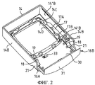
Фиг.2 представляет собой схематический вид, идентичный виду, показанному на фиг.1, причем в данном случае подвижная часть козырька в максимально возможной степени введена в рамку корпуса;Figure 2 is a schematic view identical to the view shown in figure 1, and in this case, the movable part of the peak is inserted as much as possible into the frame of the housing;
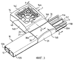
Фиг.3 представляет собой схематический вид в перспективе сверху корпуса, показанного на фиг.1 и 2, но установленного на монтажный короб;Figure 3 is a schematic perspective view from above of the housing shown in figures 1 and 2, but mounted on a mounting box;
Фиг.4 представляет собой схематический вид в разрезе по плоскости А-А, показанной на фиг.3;Figure 4 is a schematic sectional view along the plane AA shown in figure 3;
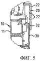
Фиг.5 представляет собой детальный схематический вид в разрезе по плоскости В-В, показанной на фиг.3;Figure 5 is a detailed schematic sectional view along the plane BB shown in figure 3;
Фиг.6 представляет собой схематический вид в перспективе, идентичный видам, показанным на фиг.1 и 2, причем в данном случае подвижная часть козырька соединена с рамкой корпуса на заключительной стадии изготовления;6 is a schematic perspective view identical to the views shown in figures 1 and 2, and in this case, the movable part of the visor is connected to the frame of the housing at the final stage of manufacture;
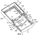
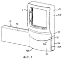
Фиг.7 представляет собой схематический вид варианта реализации корпуса в соответствии с предлагаемым изобретением, установленного на конце монтажного короба;Fig.7 is a schematic view of a variant of implementation of the housing in accordance with the invention, mounted on the end of the mounting box;
Фиг.8 представляет собой схематический вид другого варианта реализации корпуса в соответствии с предлагаемым изобретением.Fig. 8 is a schematic view of another embodiment of a housing in accordance with the invention.
Как изображено на приведенных фигурах, и по существу известным образом, речь в данном случае идет о размещении вдоль монтажного короба 10, установленного выступающим образом на стенке или перегородке, не показанной на приведенных фигурах, электротехнического оборудования, также не показанного здесь, используя для размещения корпус 1.As shown in the figures, and in a generally known manner, we are talking about the placement along the
Такое техническое решение наиболее наглядно представлено на фиг.3.Such a technical solution is most clearly presented in figure 3.
В варианте реализации, представленном на фиг.3 и по существу известном, монтажный короб 10 содержит, в целом, основание 11, посредством которого этот монтажный короб закреплен на соответствующей стенке или перегородке и поперечное сечение которого является открытым, и крышку 12, которая присоединена, например, путем защелкивания, к этому основанию 11 для его перекрытия.In the embodiment shown in FIG. 3 and substantially known, the
Основание 11 монтажного короба ограничено по бокам двумя продольными крыльями 11А, 11В и внутреннее пространство этого основания разделено в продольном направлении на две равные части посредством центральной перегородки 11С, верхний край которой выходит по существу на уровень изгибов продольных крыльев 11А и 11В.The
В данном случае используется крышка 12 перекрывающего типа. Это означает, что она содержит опускающиеся боковые кромки 12А и 12В, закрывающие наружные поверхности боковых крыльев 11А и 11В основания 11 монтажного короба 10.In this case, the
Корпус 1 установлен обычно между двумя участками крышки, причем один из этих участков показан на фиг.3.The housing 1 is usually installed between two sections of the cover, and one of these sections is shown in Fig.3.
Как показано на приведенных фигурах, этот корпус 1 содержит, с одной стороны, рамку 14, которая, будучи приспособленной для закрепления на предназначенной для размещения данного оборудования стенке (на приведенных фигурах не показана) вдоль монтажного короба 10, образует гнездо для оборудования и, более конкретно, для механизма этого оборудования, и которая, вдоль той из своих сторон, посредством которой она должна примыкать к монтажному коробу 10, содержит отверстие 15, а с другой стороны, козырек 16, который, проходя с учетом особенностей данной рамки 14, точнее говоря, проходя от верхней части ее отверстия 15, предназначен для локального поперечного перекрытия монтажного короба 10, практически заходя на основание 11 этого монтажного короба 10 между двумя участками его крышки 12 (смотри, в частности, фиг.3).As shown in the figures, this housing 1 contains, on the one hand, a
Рамка 14 содержит фасадную стенку 14А, снабженную фронтальным отверстием 14С, предназначенным для прохождения доступного для пользователя участка устанавливаемого оборудования, а также две параллельные боковые стенки 14В и заднюю стенку, не обозначенную отдельной позицией.The
Корпус 1 дополняется (смотри, в частности, фиг.3) панелью 40, которая обеспечивает возможность закрепления данной системы на рассматриваемой стенке. Рамка 14 накрывает панель 40 таким образом, чтобы образовать гнездо, предназначенное для размещения соответствующего оборудования, причем эта панель образует опору, предназначенную для размещения на ней механизма данного оборудования и закрепленную на рамке при помощи защелкивания или эквивалентной системы закрепления.The housing 1 is supplemented (see, in particular, figure 3) with a
Как более наглядно показано на фиг.1-6, козырек 16 корпуса 1 содержит неподвижную часть 16А, жестко соединенную с рамкой 14, и подвижную часть 16В, снабженную двумя параллельными кронштейнами 17, которые установлены с возможностью скольжения внутри рамки таким образом, чтобы позиционирование подвижной части 16В козырька 16 по отношению к рамке 14 или, точнее говоря, по отношению к неподвижной части 16А этого козырька, выполнялось телескопически и соответствовало последовательности устойчивых фиксированных положений, учитывающих возможные различные значения ширины используемого в данном случае монтажного короба.1-6, the
В соответствии со способом реализации, схематически представленным на фиг.1-6, неподвижная часть 16А козырька 16 выполнена за одно целое с рамкой 14 корпуса и содержит, с одной стороны, переднюю стенку 20, которая, начиная от отверстия 15 рамки 14, точнее, начиная от верхней части этого отверстия 15, продолжает на некоторую высоту фасадную стенку 14А рамки 14 корпуса 1, а с другой стороны, две боковые стенки 21, каждая из которых продолжает одну из двух параллельных боковых стенок 14В рамки 14 корпуса.In accordance with the implementation method, schematically represented in FIGS. 1-6, the
Подвижная часть 16В козырька 16 содержит переднюю стенку 30, два параллельных боковых края которой 30А продолжаются кронштейнами 17, и стенку торцевой заслонки 31, расположенную перпендикулярно по отношению к передней стенке 30 от ее переднего края, противоположного кронштейнам, причем эта передняя стенка 30 подвижной части 16В козырька имеет возможность скольжения под передней стенкой 20 неподвижной части 16А этого козырька.The
Как более наглядно показано на фиг.3, передние стенки 20 и 30 неподвижной части 16А и подвижной части 16В козырька 16, а также стенка торцевой заслонки 31 подвижной части 16В, совместно обеспечивают целостность или непрерывность перегородки между участками крышки 12, причем стенка торцевой заслонки 31 подвижной части 16В козырька 16 перекрывает опускающиеся края смежных участков этой крышки 12.As shown more clearly in FIG. 3, the
В соответствии с примером реализации, более наглядно представленным на фиг.1, 2 и 5, внутренняя поверхность передней стенки 20 неподвижной части 16А козырька 16 содержит ряд вырезов 22, ступенчато расположенных или разнесенных по высоте этой стенки, и наружная поверхность передней стенки 30 подвижной части 16В козырька 16 содержит слегка выступающее ребро жесткости 32, выполненное с возможностью взаимодействия с вырезами 22 для обеспечения возможности позиционирования в совокупности устойчивых фиксированных положений подвижной части 16В козырька 16 по отношению к неподвижной части 16А этого козырька.In accordance with an example implementation, more clearly shown in FIGS. 1, 2, and 5, the inner surface of the
Кроме того, в предпочтительном варианте реализации против вырезов 22, выполненных на внутренней поверхности передней стенки 20 неподвижной части 16А козырька 16, на этой внутренней поверхности выполнена цифровая индикация значения ширины или высоты козырька.In addition, in a preferred embodiment, against
В данном случае предусмотрены четыре значения ширины или высоты этого козырька, соответствующие четырем возможным значениям ширины или высоты используемого в данном случае монтажного короба или настенной накладки.In this case, four values of the width or height of this visor are provided, corresponding to four possible values of the width or height of the mounting box or wall plate used in this case.
Кроме того, в передней стенке 30 подвижной части 16В козырька 16 выполнен специальный вырез 33, обеспечивающий возможность визуального контроля цифровой индикации ширины или высоты данного козырька в том случае, когда его подвижная часть установлена в одно из четырех возможных устойчивых фиксированных положений по отношению к неподвижной части этого козырька.In addition, a
Так, в положении, показанном на фиг.1, подвижная часть 16В козырька 16 установлена в крайнем положении, соответствующем наибольшей ширине или высоте козырька, имеющем цифровое обозначение 40, а на фиг.2 эта подвижная часть 16В козырька 16 установлена в ее противоположное крайнее положение, соответствующее наименьшей ширине или высоте этого козырька и имеющее цифровое обозначение 16.So, in the position shown in figure 1, the
Между двумя этими предельными положениями, максимальным и минимальным, предусмотрены два промежуточных положения, обозначенных цифровыми значениями 25 и 32, которые соответствуют двум другим значениям ширины или высоты других типов стандартного монтажного короба.Between these two limit positions, maximum and minimum, two intermediate positions are provided, indicated by
Очевидно, что в соответствии с другими возможными способами реализации, не показанными на приведенных фигурах, можно предусмотреть и другие дополнительные средства блокировки, предназначенные для определения совокупности устойчивых фиксированных положений подвижной части козырька по отношению к рамке, точнее говоря, по отношению к неподвижной части этого козырька, жестко соединенной с этой рамкой, соответствующих различным значениям ширины или высоты используемого в данном случае монтажного короба.Obviously, in accordance with other possible implementation methods, not shown in the figures, it is possible to provide other additional locking means designed to determine the set of stable fixed positions of the movable part of the visor with respect to the frame, more precisely, with respect to the fixed part of this visor rigidly connected to this frame, corresponding to different values of the width or height of the mounting box used in this case.
В соответствии с первым из этих возможных вариантов реализации можно предусмотреть, чтобы одна из передних стенок подвижной и неподвижной частей козырька содержала совокупность выступающих элементов жесткости, ступенчато расположенных или разнесенных по высоте этой передней стенки, а другая из этих передних стенок содержала вырез, выполненный с возможностью взаимодействия с этими выступающими элементами жесткости для обеспечения взаимного позиционирования в соответствии с совокупностью устойчивых фиксированных положений подвижной части данного козырька по отношению к его неподвижной части.In accordance with the first of these possible embodiments, it can be provided that one of the front walls of the movable and fixed parts of the visor contains a set of protruding stiffeners, stepwise spaced or spaced apart along the height of this front wall, and the other of these front walls contains a cutout configured to interaction with these protruding stiffeners to ensure mutual positioning in accordance with a set of stable fixed positions of movable the second part of the canopy relative to its fixed part.
В этом случае вырез предпочтительно выполнен на внутренней поверхности передней стенки неподвижной части данного козырька, а элементы жесткости образуют небольшие выступы на наружной поверхности передней стенки подвижной части этого козырька.In this case, the cutout is preferably made on the inner surface of the front wall of the fixed part of the visor, and the stiffeners form small protrusions on the outer surface of the front wall of the movable part of this visor.
Дополнительные средства блокировки также могут содержать вырезы, выполненные на различных уровнях на наружных краях кронштейнов подвижной части козырька и предназначенные для взаимодействия с единственным выступающим элементом жесткости, выполненным на каждой из соответствующих внутренних поверхностей параллельных боковых стенок рамки.Additional locking means may also include cutouts made at different levels on the outer edges of the brackets of the movable part of the visor and designed to interact with a single protruding stiffener made on each of the corresponding inner surfaces parallel to the side walls of the frame.
Эти дополнительные средства блокировки также могут содержать вырезы, выполненные на различных уровнях по высоте на внутренней поверхности соответствующих боковых стенок рамки и обеспечивающие взаимодействие с выступающими элементами жесткости, предусмотренными на каждом из наружных краев кронштейнов.These additional locking means may also include cutouts made at different levels in height on the inner surface of the respective side walls of the frame and allowing interaction with protruding stiffeners provided on each of the outer edges of the brackets.
В качестве дополнительных средств блокировки можно также предусмотреть наличие совокупности вырезов, выполненных на соответствующих кронштейнах и взаимодействующих с двумя дополнительными упорами, расположенными на концах двух гибких пластин, предусмотренных на рамке и располагающихся против кронштейнов.As additional locking means, it is also possible to provide for a set of cuts made on the respective brackets and interacting with two additional stops located at the ends of two flexible plates provided on the frame and located against the brackets.
В то же время, как более наглядно показано на фиг.2 и 4, кронштейны 17 содержат на своих поверхностях, ориентированных в направлении панели данного корпуса, два разнесенных по высоте упора, причем первый из этих упоров 17А расположен в непосредственной близости от свободного конца каждого из кронштейнов, а второй упор 17В размещается на некотором расстоянии от свободного конца соответствующего кронштейна и более удален от него.At the same time, as is more clearly shown in FIGS. 2 and 4, the
Эти упоры 17А и 17В выполнены с возможностью взаимодействия с упором 18А, который размещен на конце гибкой пластины 18, жестко закрепленной на рамке 14, и ориентирован в направлении соответствующего кронштейна 17.These
Каждая гибкая пластина 18 закреплена на рамке 14 посредством консоли 19, выполненной в виде рамки, выступающей на внутренней поверхности 14’В каждой боковой стенки 14В рамки 14, и располагающейся в непосредственной близости от отверстия 15 данной рамки.Each
Каждая такая гибкая пластина 18 имеет в целом S-образную или зигзагообразную форму, чтобы верхняя часть этой пластины, обращенная в сторону кронштейна 17, была по существу плоской и параллельной этому кронштейну, и чтобы эта гибкая пластина содержала на своем свободном конце упор 18А.Each such
Очевидно, что могут быть предусмотрены и другие приспособленные соответствующим образом формы, применяемые для реализации этих гибких пластин.Obviously, other appropriately adapted forms used to implement these flexible plates may also be provided.
Взаимодействие упоров 17А, 17В, 18А в предпочтительном варианте реализации образует средство взаимного соединения и направляющего воздействия для подвижных и неподвижных частей 16А и 16В козырька 16.The interaction of the
Действительно, первый упор 17А, расположенный в непосредственной близости от свободного конца каждого кронштейна 17, позволяет окончательно соединить подвижную часть 16В козырька с рамкой 14 корпуса (точнее говоря, с неподвижной частью 16А козырька, жестко связанной с этой рамкой) в процессе ее изготовления. Это позволяет облегчить процесс установки данной системы пользователем, уменьшить объем системы, образованной корпусом и козырьком, при ее упаковке и облегчить, тем самым, упаковку такой системы.Indeed, the
В собранном положении подвижная и неподвижная части козырька в процессе изготовления корпуса наиболее наглядно показаны на фиг.6. Следует отметить, что, как показано на фиг.6, гибкие пластины 18 взаимодействуют с упорами 17А, расположенными в непосредственной близости от свободных концов соответствующих кронштейнов, как указано выше.In the assembled position, the movable and fixed parts of the visor during the manufacturing process of the housing are most clearly shown in Fig.6. It should be noted that, as shown in Fig.6, the
В том случае, когда монтажник хочет установить корпус вдоль монтажного короба, он должен ввести подвижную часть 16В козырька 16 внутрь рамки 14 корпуса таким образом, чтобы при помощи упругой деформации гибких пластин 18 упоры 17А могли преодолеть упоры, размещенные на этих гибких пластиках, в результате чего происходит взаимодействие между упорами 17В, размещенными на кронштейнах, и упорами 18А, размещенными на гибких пластинах 18, причем это взаимодействие упоров определяет крайнее положение наибольшей ширины козырька, соответствующее цифровому обозначению 40.In the event that the installer wants to install the housing along the mounting box, he must insert the
В качестве возможного варианта реализации на кронштейнах 17 могут быть выполнены только упоры 17В, причем в этом случае подвижная часть козырька поставляется, после изготовления корпуса, в положении установки в крайнее положение наибольшей ширины этого козырька.As a possible embodiment, only the
В процессе эксплуатации гибкие пластины 18, выполненные на рамке 14 корпуса, обеспечивают возможность придания данной системе определенной гибкости. Благодаря упругости этих гибких пластин 18, подвижная часть 16В козырька 16 может воспринимать по отношению к своей неподвижной части 16А или по отношению к рамке 14 отклонение на некоторый угол по одну и по другую стороны от ее центрированного положения.During operation,
Такое конструктивное решение предпочтительно позволяет преодолеть неблагоприятное влияние возможных дефектов плоскостности поверхностей, на которые может быть установлен данный корпус.This constructive solution preferably allows you to overcome the adverse effects of possible defects in the flatness of the surfaces on which this housing can be installed.
В то же время, как более наглядно показано на фиг.1 и 2, каждый кронштейн 17 в данном случае предпочтительно имеет ширину, отрегулированную по ширине свободного пространства, существующего между внутренней поверхностью 14’D бокового края 14D фронтального отверстия 14С рамки корпуса и внутренней поверхностью 14’В боковой стенки 14В рамки 14, расположенной против соответствующего бокового края 14D, таким образом, чтобы это внутреннее пространство образовало направляющую канавку скольжения для кронштейна 17.At the same time, as is more clearly shown in FIGS. 1 and 2, each
Таким образом, в данном случае не предусматриваются дополнительные средства, предназначенные для обеспечения скольжения кронштейнов внутри рамки корпуса.Thus, in this case, no additional means are provided for ensuring the sliding of the brackets inside the frame of the housing.
В предпочтительном варианте реализации избыточная длина передней стенки 30 подвижной части 16В козырька скрывается под передней стенкой 20 неподвижной части 16А этого козырька и кронштейны 17 имеют возможность скольжения в предварительно образованном пространстве рамки 14 корпуса таким образом, чтобы подвижная часть 16В козырька не взаимодействовала неблагоприятным образом с другими элементами, располагающимися в этом корпусе.In a preferred embodiment, the excess length of the
Очевидно, что в специфическом варианте реализации, не представленном в качестве примера на чертежах, можно предусмотреть, чтобы кронштейны 17 имели возможность скольжения в специальных канавках, образованных на внутренних поверхностях двух параллельных боковых стенок рамки корпуса.Obviously, in a specific embodiment, not shown as an example in the drawings, it can be envisaged that the
В соответствии с вариантом реализации, более наглядно представленным на фиг.7, и в том случае, когда корпус 1 установлен на конце используемого в данном случае монтажного короба 10, предпочтительно предусматривается наличие стенки перекрытия или торцевой перекрывающей заслонки 34, установленной на боковой стороне подвижной части 16В козырька, отрегулированного по ширине данного монтажного короба, и обеспечивающей целостность или непрерывность боковой стенки 14В рамки 14 корпуса для того, чтобы перекрыть соответствующий свободный конец этого монтажного короба.In accordance with the implementation embodiment, more clearly shown in Fig.7, and in the case when the housing 1 is installed at the end of the mounting
Эта торцевая перекрывающая заслонка 34 может быть специально присоединена или выполнена в виде единой детали с подвижной частью 16В козырька 16.This
На фиг.8 схематически представлен другой вариант реализации корпуса в соответствии с предлагаемым изобретением. В этом варианте реализации неподвижная часть 16А козырька 16 присоединена к рамке 14, причем эта неподвижная часть 16А козырька содержит переднюю стенку 20, продолжающую фасадную стенку 14А рамки 14 корпуса 1.On Fig schematically presents another embodiment of the housing in accordance with the invention. In this embodiment, the fixed
В этом случае высота этой передней стенки соответствует ширине используемого монтажного короба (на фиг.8 не показан) для того, чтобы локальным образом и в поперечном по отношению к нему направлении закрыть этот монтажный короб.In this case, the height of this front wall corresponds to the width of the mounting box used (not shown in Fig. 8) in order to close this mounting box locally and transversely with respect to it.
Данная передняя стенка 20 козырька содержит на том своем конце, который должен взаимодействовать с рамкой 14, уступ стенки 23, отрегулированный для введения в отверстие 15 рамки 14 корпуса и содержащий в своей нижней части вырезы 23А, предназначенные для соединения рамки 14 с этой неподвижной частью 16А козырька.This
Кроме того, передняя стенка 20 неподвижной части 16А козырька 16 содержит продольные опускающиеся края 20А, которые способны перекрыть участки крышки, установленные на данный монтажный короб.In addition, the
В соответствии с этим вариантом реализации подвижная часть 16В козырька 16 содержит стенку торцевой заслонки 31, от которой отходят кронштейны 17, расположенные перпендикулярно по отношению к этой стенке, причем стенка торцевой заслонки 31 может быть размещена на свободном конце передней стенки 20 неподвижной части перпендикулярно к ней для того, чтобы локально обеспечить целостность или непрерывность бокового крыла основания данного монтажного короба, или опускающегося края участка его крышки.In accordance with this embodiment, the
Как указано выше, кронштейны 17 снабжены средствами блокировки, взаимодействующими с дополнительными средствами блокировки, выполненными на рамке корпуса, для обеспечения блокировки данной системы в требуемом положении.As indicated above, the
Неподвижная часть 16А козырька существует для различных значений длины, по одному на каждое значение ширины или высоты используемого в данном случае монтажного короба, и рабочий ход подвижной части 16В козырька оптимизирован таким образом, чтобы быть ограниченным только по длине рамки 14 данного корпуса.The fixed
Очевидно, что части описанного здесь корпуса изготавливаются из того или иного пластического материала путем литья.Obviously, parts of the body described herein are made of a particular plastic material by casting.
Кронштейны, а также передняя стенка и стенка торцевой заслонки подвижной части козырька, образуют единую деталь, изготавливаемую путем формования того или иного пластического материала.The brackets, as well as the front wall and the wall of the end flap of the movable part of the visor, form a single part made by molding one or another plastic material.
Предлагаемое изобретение не ограничивается теми примерами его реализации, которые были описаны и проиллюстрированы в данном описании, и специалист в данной области техники сможет внести в эти примеры любые изменения, не меняющие существа заявленного изобретения.The present invention is not limited to those examples of its implementation that have been described and illustrated in this description, and a person skilled in the art can make any changes to these examples that do not change the essence of the claimed invention.
Claims (15)
Applications Claiming Priority (2)
| Application Number | Priority Date | Filing Date | Title |
|---|---|---|---|
| FR0003784 | 2000-03-24 | ||
| FR0003784A FR2806846B1 (en) | 2000-03-24 | 2000-03-24 | APPARATUS HOUSING AVAILABLE ALONG A CHUTE, ESPECIALLY FOR ELECTRIC APPARATUS |
Publications (2)
| Publication Number | Publication Date |
|---|---|
| RU2001107892A RU2001107892A (en) | 2003-03-10 |
| RU2256269C2 true RU2256269C2 (en) | 2005-07-10 |
Family
ID=8848478
Family Applications (1)
| Application Number | Title | Priority Date | Filing Date |
|---|---|---|---|
| RU2001107892/09A RU2256269C2 (en) | 2000-03-24 | 2001-03-23 | Housing for equipment designed for installation along wiring duct |
Country Status (14)
| Country | Link |
|---|---|
| US (1) | US6663199B1 (en) |
| EP (1) | EP1139537B1 (en) |
| AR (1) | AR029049A1 (en) |
| AT (1) | ATE443364T1 (en) |
| BR (1) | BR0101573A (en) |
| DE (1) | DE60139911D1 (en) |
| DK (1) | DK1139537T3 (en) |
| ES (1) | ES2333696T3 (en) |
| FR (1) | FR2806846B1 (en) |
| HU (1) | HUP0101169A3 (en) |
| MX (1) | MXPA01002438A (en) |
| PL (1) | PL207715B1 (en) |
| PT (1) | PT1139537E (en) |
| RU (1) | RU2256269C2 (en) |
Cited By (1)
| Publication number | Priority date | Publication date | Assignee | Title |
|---|---|---|---|---|
| RU2717572C2 (en) * | 2015-10-21 | 2020-03-24 | Легран Франс | Electric box embedded into partitions of different thicknesses |
Families Citing this family (4)
| Publication number | Priority date | Publication date | Assignee | Title |
|---|---|---|---|---|
| US10109989B1 (en) * | 2013-03-09 | 2018-10-23 | Jeffrey Baldwin | Cable conduit electrical box |
| US9312670B1 (en) * | 2013-03-09 | 2016-04-12 | Jeffrey Baldwin | Sealed cable conduit electrical box |
| DE102015013861A1 (en) * | 2015-10-28 | 2017-05-04 | Gabo Systemtechnik Gmbh | Cable duct section, cable duct and cable duct system |
| CN117117641B (en) * | 2023-10-24 | 2024-01-02 | 山西通信通达微波技术有限公司 | Multifunctional power distribution cabinet for communication network base station |
Family Cites Families (15)
| Publication number | Priority date | Publication date | Assignee | Title |
|---|---|---|---|---|
| US3721762A (en) * | 1971-12-08 | 1973-03-20 | Plastic J Corp | Electrical raceway and decorative molding |
| DE3412038A1 (en) * | 1984-03-31 | 1985-10-03 | Tehalit Kunststoffwerk Gmbh, 6751 Heltersberg | DEVICE MOUNTING UNIT FOR SKIRTING INSTALLATION CHANNELS |
| FR2595513B1 (en) * | 1986-03-10 | 1994-04-08 | Legrand | ADAPTER SUPPORT FOR ELECTRICAL EQUIPMENT |
| FR2605152B1 (en) * | 1986-10-08 | 1989-01-13 | Planet Wattohm Cie | BYPASS ACCESSORY FOR WIRING DUCT |
| IT218910Z2 (en) * | 1989-10-24 | 1992-11-10 | Bticino Spa | INTERCONNECTION ELEMENT FOR MODULAR DUCTS INTENDED FOR THE INSTALLATION AND CONTAINMENT OF ELECTRIC CONDUCTOR CABLES |
| IE921218A1 (en) * | 1992-04-16 | 1993-10-20 | Perfectly Possible Ltd | Improvements in and relating to trunking |
| ES2077498B1 (en) * | 1993-07-05 | 1996-11-16 | Aparellaje Electrico Sa | ADAPTER DEVICE FOR AN ELECTRICAL MECHANISM TO A DUCT. |
| US5421646A (en) * | 1993-07-12 | 1995-06-06 | Minnesota American, Inc. | Legless locker shelf assembly |
| US5486650A (en) * | 1993-11-15 | 1996-01-23 | Hubbell Incorporated | Partition for dividing a device box |
| ES2112168B1 (en) * | 1995-07-12 | 1998-11-01 | Aparellaje Electrico Sa | JUNCTION BOX FOR ELECTRIC DUCTS. |
| FR2758016B1 (en) * | 1996-12-31 | 1999-03-12 | Legrand Sa | METHOD AND DEVICE FOR STRENGTHENING THE HOLDING ON A CHUTE OF ANY ACCESSORY TO BE FITTED BY NESTING ON THE BASE THEREOF |
| US5747733A (en) * | 1997-03-03 | 1998-05-05 | Woods; Randall T. | Wiring duct entrance fitting enclosure |
| US5998732A (en) * | 1998-01-13 | 1999-12-07 | Panduit Corp. | Raceway outlet station |
| FR2786616B1 (en) * | 1998-11-27 | 2001-02-16 | Legrand Sa | SUPPORT FOR APPARATUS AVAILABLE ALONG A CHUTE WITH CANOPY IN MULTIPLE PARTS |
| FR2786617B1 (en) * | 1998-11-27 | 2001-03-16 | Legrand Sa | BOX FOR EQUIPMENT TO BE PLACED ALONG A TRUNKING, PARTICULARLY FOR ELECTRICAL EQUIPMENT |
-
2000
- 2000-03-24 FR FR0003784A patent/FR2806846B1/en not_active Expired - Fee Related
-
2001
- 2001-02-19 AT AT01400432T patent/ATE443364T1/en active
- 2001-02-19 DE DE60139911T patent/DE60139911D1/en not_active Expired - Lifetime
- 2001-02-19 PT PT01400432T patent/PT1139537E/en unknown
- 2001-02-19 EP EP01400432A patent/EP1139537B1/en not_active Expired - Lifetime
- 2001-02-19 DK DK01400432T patent/DK1139537T3/en active
- 2001-02-19 ES ES01400432T patent/ES2333696T3/en not_active Expired - Lifetime
- 2001-03-08 MX MXPA01002438A patent/MXPA01002438A/en active IP Right Grant
- 2001-03-16 PL PL346494A patent/PL207715B1/en unknown
- 2001-03-22 AR ARP010101334A patent/AR029049A1/en active IP Right Grant
- 2001-03-22 US US09/813,860 patent/US6663199B1/en not_active Expired - Fee Related
- 2001-03-23 BR BR0101573-7A patent/BR0101573A/en not_active IP Right Cessation
- 2001-03-23 RU RU2001107892/09A patent/RU2256269C2/en not_active IP Right Cessation
- 2001-03-23 HU HU0101169A patent/HUP0101169A3/en unknown
Cited By (1)
| Publication number | Priority date | Publication date | Assignee | Title |
|---|---|---|---|---|
| RU2717572C2 (en) * | 2015-10-21 | 2020-03-24 | Легран Франс | Electric box embedded into partitions of different thicknesses |
Also Published As
| Publication number | Publication date |
|---|---|
| PL346494A1 (en) | 2001-10-08 |
| PT1139537E (en) | 2009-12-21 |
| US6663199B1 (en) | 2003-12-16 |
| EP1139537A1 (en) | 2001-10-04 |
| DK1139537T3 (en) | 2010-01-04 |
| MXPA01002438A (en) | 2003-08-20 |
| HU0101169D0 (en) | 2001-05-28 |
| FR2806846B1 (en) | 2002-06-21 |
| FR2806846A1 (en) | 2001-09-28 |
| HUP0101169A2 (en) | 2002-01-28 |
| BR0101573A (en) | 2001-11-13 |
| PL207715B1 (en) | 2011-01-31 |
| EP1139537B1 (en) | 2009-09-16 |
| ATE443364T1 (en) | 2009-10-15 |
| DE60139911D1 (en) | 2009-10-29 |
| HUP0101169A3 (en) | 2002-02-28 |
| AR029049A1 (en) | 2003-06-04 |
| ES2333696T3 (en) | 2010-02-26 |
Similar Documents
| Publication | Publication Date | Title |
|---|---|---|
| US6395981B1 (en) | Multiple gang junction box assembly with electrical arcing isolation between compartments | |
| EP1363375B1 (en) | Wire harness protector | |
| EP1160949B1 (en) | Raceway with split cover | |
| EP0929138B1 (en) | Raceway outlet station | |
| RU2243623C2 (en) | Holding clamp for installation and wiring duct | |
| EP0633639B1 (en) | Device for adapting an electrical mechanism to a raceway means for electrical conductors | |
| US5259787A (en) | Mounting assembly | |
| US7390977B2 (en) | Hanging box and faceplate adapter | |
| RU2477554C2 (en) | Angular accessory for boxes | |
| CN1087133C (en) | Mounting frame for electronic module | |
| RU2256269C2 (en) | Housing for equipment designed for installation along wiring duct | |
| CN104471811A (en) | Arm power supply device | |
| US6566600B1 (en) | Multiple gang junction box assembly with separate lockable divider panels | |
| RU2226733C2 (en) | Box for instrument, in particular, electric instrument, installed along a tray | |
| HU222825B1 (en) | Accessory with access eye for duct | |
| AU2014303734A1 (en) | Cable-holding bracket | |
| US7198423B2 (en) | Skirting duct angle accessory comprising two flaps assembled together at an angle | |
| HU223720B1 (en) | Electrical equipment support for attachment to trunking | |
| RU2253173C2 (en) | Insulating duct for electrical equipment mounted on tray socle by means of installation and wiring bracket | |
| EP3628543B1 (en) | Wire harness | |
| PT1137142E (en) | Electrical apparatus box to be placed alongside a cableduct | |
| HU222998B1 (en) | Fixable box for duct, especially for electric equipment | |
| PL192980B1 (en) | Coupling member for trough sections | |
| US20010052563A1 (en) | Branch connection accessory for fitting at a junction between two lengths of trunking | |
| RU2485653C2 (en) | Device for installation of electrical unit in duct for electric cables and wires routing and node containing electrical unit and above unit |
Legal Events
| Date | Code | Title | Description |
|---|---|---|---|
| PD4A | Correction of name of patent owner | ||
| MM4A | The patent is invalid due to non-payment of fees |
Effective date: 20180324 |