RU2249305C2 - Method for data stream emulation - Google Patents
Method for data stream emulation Download PDFInfo
- Publication number
- RU2249305C2 RU2249305C2 RU2002124604/09A RU2002124604A RU2249305C2 RU 2249305 C2 RU2249305 C2 RU 2249305C2 RU 2002124604/09 A RU2002124604/09 A RU 2002124604/09A RU 2002124604 A RU2002124604 A RU 2002124604A RU 2249305 C2 RU2249305 C2 RU 2249305C2
- Authority
- RU
- Russia
- Prior art keywords
- network element
- packet
- packets
- network
- transmitted
- Prior art date
Links
Images

Classifications
-
- H—ELECTRICITY
- H04—ELECTRIC COMMUNICATION TECHNIQUE
- H04L—TRANSMISSION OF DIGITAL INFORMATION, e.g. TELEGRAPHIC COMMUNICATION
- H04L69/00—Network arrangements, protocols or services independent of the application payload and not provided for in the other groups of this subclass
- H04L69/16—Implementation or adaptation of Internet protocol [IP], of transmission control protocol [TCP] or of user datagram protocol [UDP]
- H04L69/164—Adaptation or special uses of UDP protocol
-
- H—ELECTRICITY
- H04—ELECTRIC COMMUNICATION TECHNIQUE
- H04L—TRANSMISSION OF DIGITAL INFORMATION, e.g. TELEGRAPHIC COMMUNICATION
- H04L43/00—Arrangements for monitoring or testing data switching networks
- H04L43/50—Testing arrangements
-
- H—ELECTRICITY
- H04—ELECTRIC COMMUNICATION TECHNIQUE
- H04L—TRANSMISSION OF DIGITAL INFORMATION, e.g. TELEGRAPHIC COMMUNICATION
- H04L69/00—Network arrangements, protocols or services independent of the application payload and not provided for in the other groups of this subclass
- H04L69/16—Implementation or adaptation of Internet protocol [IP], of transmission control protocol [TCP] or of user datagram protocol [UDP]
- H04L69/163—In-band adaptation of TCP data exchange; In-band control procedures
-
- H—ELECTRICITY
- H04—ELECTRIC COMMUNICATION TECHNIQUE
- H04L—TRANSMISSION OF DIGITAL INFORMATION, e.g. TELEGRAPHIC COMMUNICATION
- H04L9/00—Cryptographic mechanisms or cryptographic arrangements for secret or secure communications; Network security protocols
- H04L9/40—Network security protocols
-
- H—ELECTRICITY
- H04—ELECTRIC COMMUNICATION TECHNIQUE
- H04L—TRANSMISSION OF DIGITAL INFORMATION, e.g. TELEGRAPHIC COMMUNICATION
- H04L1/00—Arrangements for detecting or preventing errors in the information received
- H04L1/12—Arrangements for detecting or preventing errors in the information received by using return channel
- H04L1/16—Arrangements for detecting or preventing errors in the information received by using return channel in which the return channel carries supervisory signals, e.g. repetition request signals
- H04L1/18—Automatic repetition systems, e.g. Van Duuren systems
Abstract
Description
Данное изобретение относится к эмуляции двухстороннего информационного потока реального применения. В частности, но не обязательно, изобретение относится к эмуляции информационного потока вызова речь по Интернет-протоколу (РИП) для определения качества обслуживания (КО) уровня применения РИП.This invention relates to the emulation of a two-way information flow of a real application. In particular, but not necessarily, the invention relates to the emulation of the information flow of a call using speech over the Internet Protocol (RIP) to determine the quality of service (Qo) level of application of the RIP.
Обычно речевой вызов по телефону посылают по сетям с коммутацией каналов, таким как коммутируемая телефонная сеть общего пользования (PSTN, КТСОП). При телефонном вызове по цифровой сети с коммутацией каналов для каждого вызова устанавливают постоянное соединения 64 кб/с. Эта стандартная полоса соединения, 64 кб/с, объясняется скоростью передачи данных в битах, требуемой для дискретизации аналоговой речи при использовании 8-битовой импульсно-кодовой модуляции (ИКМ) при частоте дискретизации 8 кГц, в результате чего обеспечивают возможность передачи аналоговой речи с частотой 300-3400 Гц в цифровом формате.Typically, a voice call is sent over circuit-switched networks, such as a public switched telephone network (PSTN, PSTN). When making a telephone call over a circuit-switched digital network, a constant connection of 64 kb / s is established for each call. This standard bandwidth, 64 kb / s, is explained by the bit rate required to sample analog speech using 8-bit pulse-code modulation (PCM) at a sampling frequency of 8 kHz, resulting in the ability to transmit analog speech at a frequency 300-3400 Hz in digital format.
Но упоминаемая выше широко используемая в данное время цифровая телефонная сеть очень неэффективна и, поэтому, забирает значительный объем сетевых ресурсов. В телефонной сети полосу для соединения также резервируют, когда соединение не используют активно, т.е. ни одна из сторон соединения не пересылает информацию, такую как речь или данные, по этому соединению. Этот тип использования статической полосы забирает значительный объем ресурсов передачи данных, и поэтому по мере роста числа пользователей необходимо делать капиталовложения для обеспечения дополнительной пропускной способности. Неэффективность описываемого выше вида вызывает затруднения, особенно в межконтинентальных вызовах, когда повышение пропускной способности по передаче данных затруднено в еще большей степени по сравнению с другими случаями. Эта проблема также проявляется в расценках за вызовы: дополнительные капиталовложения для увеличения пропускной способности должны покрываться повышением абонентской платы.But the digital telephone network mentioned above, which is widely used at the moment, is very inefficient and, therefore, takes up a significant amount of network resources. In the telephone network, the connection band is also reserved when the connection is not actively used, i.e. neither side of the connection sends information, such as speech or data, to this connection. This type of use of the static band takes up a significant amount of data transmission resources, and therefore, as the number of users grows, investments must be made to provide additional bandwidth. The inefficiency of the type described above causes difficulties, especially in intercontinental calls, when the increase in data transmission capacity is even more difficult compared to other cases. This problem also manifests itself in call rates: additional investments to increase throughput should be covered by an increase in the monthly fee.
Для компенсирования и дополнения вызовов, которые используют резервирование статической полосы в телефонной сети, на рынок стали поступать так называемые РИП-вызовы, т.е. вызовы ИП. Обычно информацию, передаваемую в вызове ИП, такую как речь, речь и/или видеоизображение, сначала преобразуют из аналогового формата в цифровой формат, затем сжимают и преобразуют в пакеты ИП, которые передают по сети с коммутацией пакетов на основе ИП, такой как сеть Интернет, с совместным использованием полосы вместе с другим трафиком ИП. В вызовах ИП полосу можно использовать в значительной степени более эффективно, чем в вызовах, которые резервируют статическую полосу, и это обстоятельство также отражается на ценах. Помимо этого, можно использовать также более эффективные схемы кодирования, такие как, например, кодирование G.723.1.To compensate and supplement calls that use static bandwidth reservation in the telephone network, the so-called RIP calls, i.e. IP calls. Typically, information transmitted in an IP call, such as speech, speech and / or video, is first converted from an analog format to a digital format, then compressed and converted into IP packets, which are transmitted over an IP-based packet switched network, such as the Internet sharing a band along with other IP traffic. In IP calls, the band can be used much more efficiently than in calls that reserve a static band, and this fact also affects prices. In addition, more efficient coding schemes, such as, for example, G.723.1 coding, can also be used.
Время поступления передаваемых пакетов ИП к получателю неизвестно до прибытия пакетов. И поскольку ИП маршрутизирует информационный поток попакетно, поэтому время распространения пакетов от отправителя к получателю может значительно варьироваться, и порядок пакетов может изменяться. Помимо этого, пакеты могут теряться, например, в результате переполнения поступающих данных, происходящего в буферах маршрутизаторов. За счет применения надежного протокола ИП потери пакетов можно выявлять автоматически на уровне протокола, и потерянные пакеты можно передавать повторно. Одним из таких протоколов является протокол управления передачей данных (TCP, ПУПД).The arrival time of the transmitted IP packets to the recipient is unknown before the arrival of the packets. And since the IP routes the information flow packet by packet, therefore, the propagation time of packets from the sender to the recipient can vary significantly, and the order of the packets can change. In addition, packets may be lost, for example, as a result of an overflow of incoming data occurring in the buffers of routers. Through the use of a reliable IP protocol, packet loss can be detected automatically at the protocol level, and lost packets can be retransmitted. One of these protocols is the Transmission Control Protocol. TCP.
Но такие повторные передачи могут обусловить дополнительную изменяющуюся задержку передачи информации по сети ИП. И поскольку несколько применений, используемых при повторении речи и/или изображения, пересылаемых в реальном времени, безупречно не функционируют, если, например, в передаче информации происходит слишком большая задержка, поэтому ПУПД не является удовлетворительным для использования в качестве протокола, применяемого согласно ИП в вызовах ИП. Поэтому в вызовах ИП обычно используют протокол дейтаграмм пользователя (ПДП), когда повторные передачи отсутствуют. Вместо этого, при установлении вызова рекомендуют применение ПУПД, чтобы установление вызова происходило как можно надежнее.But such retransmissions can cause an additional changing delay in the transmission of information over the IP network. And since several applications used in the repetition of speech and / or images sent in real time do not work flawlessly, if, for example, there is too much delay in the transmission of information, so the PDP is not satisfactory for use as a protocol used according to IP in IP calls. Therefore, in IP calls, the user datagram protocol (DAP) is usually used when there are no retransmissions. Instead, when establishing a call, it is recommended that the PDPM be used so that the call is established as reliably as possible.
Например, только по той причине, что применения, используемые при повторении информации в реальном времени, передаваемой по сети ИП, должны отвечать высоким требованиям с точки зрения реального времени, чтобы функционировать безотказно, поэтому необходимы некоторые меры для гарантирования качества обслуживания (КО) для данного вызова ИП. Как таковой, ИП не обеспечивает КО в том виде, в котором он предоставит гарантированное качество обслуживания. Тем не менее, имеется несколько разных методов, с помощью которых в сети ИП можно обеспечить гарантированное КО. Это, помимо прочих, методы дифференцированных услуг (ДиффУсл) и интегрированных услуг (ИнтУсл). Независимо от применяемой методики КО, важно, чтобы КО можно было измерять, чтобы определить реальную возможность обеспечения гарантированного КО для каждого вызова ИП.For example, only for the reason that the applications used in the repetition of real-time information transmitted over the IP network must meet high requirements from a real-time point of view in order to function smoothly, therefore some measures are necessary to guarantee the quality of service (QoS) for this call SP. As such, IP does not provide QoS in the form in which it will provide guaranteed quality of service. However, there are several different methods by which a guaranteed QA can be provided in the IP network. These, among others, are methods of differentiated services (DiffUsl) and integrated services (IntUsl). Regardless of the QoS methodology used, it is important that the QoS can be measured in order to determine the real possibility of providing a guaranteed QoS for each IP call.
Обычно для описания КО требуются несколько параметров КО. Так, целесообразно измерять значения для группы разных параметров КО, которые в совокупности с РИП являются, например, следующими: сквозная задержка, колебание сквозной задержки, потери пакетов и корреляция потери пакетов. В их числе сквозная задержка означает время, необходимое для прохождения пакета ИП по сети ИП от отправителя до получателя. Сквозную задержку можно также измерять как двойное прохождение сигнала в прямом и обратном направлениях, когда измеряют время, необходимое для прохождения пакета ИП от отправителя к получателю и обратно. Колебание сквозной задержки можно обозначить как, например, среднеквадратическое отклонение или дисперсию. Потери пакетов - это число передаваемых пакетов ИП, которые не получены получателем, т.е. число пакетов ИП, потерянных в пути. С точки зрения рабочих показателей системы очень важно, исчезают ли или теряются пакеты здесь и там (отсутствие корреляции потери пакетов), или теряются несколько следующих друг за другом пакетов (высокая корреляция потери пакетов).Typically, a description of QoS requires several QoS parameters. So, it is advisable to measure values for a group of different QoS parameters, which in aggregate with the RIP are, for example, the following: end-to-end delay, end-to-end delay oscillation, packet loss, and packet loss correlation. Among them, end-to-end delay means the time required for the IP packet to pass through the IP network from the sender to the recipient. The end-to-end delay can also be measured as the double passage of the signal in the forward and reverse directions, when the time required to pass the IP packet from the sender to the recipient and back is measured. The oscillation of the end-to-end delay can be denoted as, for example, standard deviation or dispersion. Packet loss is the number of transmitted IP packets that are not received by the recipient, i.e. the number of IP packets lost in transit. From the point of view of system performance, it is very important whether packets disappear or are lost here and there (lack of correlation of packet loss), or several consecutive packets are lost (high correlation of packet loss).
Фиг.1 иллюстрирует принцип измерения КО согласно известному уровню техники. Поток пакетов ИП передают от первого узла 101 сети по сети 103 ИП во второй узел сети. До передачи первый узел 101 сети вводит первую информацию в каждый передаваемый пакет ИП. Поток пакетов ИП, передаваемый первым узлом 101 сети, принимают на втором узле 102 сети, который вводит вторую информацию в пакеты ИП и возвращает их по сети 103 ИП назад в первый узел 101 сети, который вводит третью информацию в принимаемые пакеты ИП.Figure 1 illustrates the principle of measuring KO according to the prior art. The IP packet stream is transmitted from the
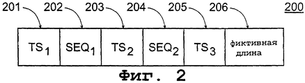
Фиг.2 иллюстрирует структуру пакета ИП, использование которого хорошо известно в структуре измерения КО, иллюстрируемой на Фиг.1. Пакет 200 ИП содержит разные типы полей для запоминания информации, введенной узлами сети в пакет ИП. Например, в полях 201 и 202 первый узел 101 сети, непосредственно перед передачей пакета ИП, запоминает данные TS1 отметки времени и данные SEQ1 порядкового номера пакета, соответственно, в качестве первой информации. В полях 203 и 204 второй узел 102 сети запоминает в качестве второй информации при приеме пакета ИП данные TS2 временной отметки и данные SEQ2 порядкового номера пакета соответственно. По получении пакета ИП: второй узел 102 сети возвращает пакет ИП немедленно назад в первый узел 101 сети, который запоминает в поле 205 в качестве третьей информации данные ТS3 отметки времени при приеме пакета ИП. Теперь параметры КО, например сквозную задержку drt, можно определить по следующему уравнению:FIG. 2 illustrates the structure of an IP packet, the use of which is well known in the QoS measurement structure illustrated in FIG.
drt=TS3-TS1 d rt = TS 3 -TS 1
Помимо полей 201-205 пакет 200 ИП в Фиг.2 содержит фиктивную длину 206. Фиктивная длина 206 является частью данных определенной длины, с помощью которой длину пакета ИП можно согласовать с размером пакетов реалистичного кодека, такого как G.711. Если пакеты 200 ИП все же передают в виде типичного единообразного потока пакетов ИП, формируемого реалистичным кодеком, то реальный вызов ИП и его измерения КО можно эмулировать с помощью упоминаемой выше структуры.In addition to fields 201-205, the
Но описываемая выше структура, известная из уровня техники, имеет свои трудности. Предположим, что пакеты 200 ИП направляют от первого узла 101 сети по сети 103 ИП во второй узел 102 сети и что передача пакетов ИП от первого узла сети во второй происходит равномерно. В идеальном случае время передачи всех пакетов ИП (сквозная задержка) от первого узла сети во второй узел сети одинаково: пакеты ИП, отправленные от первого узла сети, также прибывают во второй узел сети равномерно. Но в реальности обычно, например по причине изменяющейся нагрузки сети ИП, пакеты ИП не прибывают во второй узел сети равномерно, а пачками. Это означает, что поток пакетов ИП, прибывающих во второй узел сети, содержит уплотнения (скопления пакетов ИП) и разрывы (наличие очень длительной паузы между пакетами ИП) вместо устойчивого потока.But the structure described above, known from the prior art, has its difficulties. Suppose that
Теперь, когда второй узел сети возвращает каждый принятый им пакет ИП в первый узел сети, то поток возвращаемых пакетов ИП, уже уходя из второго узла сети, имеет выбросы и не является равномерным, как это было бы в случае реалистичного вызова ИП. В этом случае КО, присутствующее в отрывистом с выбросами потоке пакетов ИП, возвращающихся от второго узла сети в первый узел, обычно хуже, чем КО потока пакетов ИП, передаваемых равномерно от первого узла сети во второй узел сети. Эта асимметрия не характерна для реального вызова ИП, и она искажает измерения значений параметров КО. При этом, если пакеты ИП, отправляемые первым узлом сети, имеют потери по пути во второй узел сети, то поток пакетов ИП, возвращающийся из второго узла сети в первый узел сети, имеет меньше пакетов ИП, чем в первоначальном потоке пакетов ИП, отправленных от первого узла сети во второй. В этом случае в потоке пакетов ИП, возвращающихся от второго узла сети в первый, автоматически создается больше дополнительных разрывов, и это обстоятельство также повышает асимметрию.Now, when the second network node returns every IP packet it receives to the first network node, the stream of returned IP packets, already leaving the second network node, has outliers and is not uniform, as would be the case with a realistic IP call. In this case, the QoS present in the intermittent outlier stream of IP packets returning from the second network node to the first node is usually worse than the QO of the IP packet stream transmitted uniformly from the first network node to the second network node. This asymmetry is not typical for a real IP call, and it distorts the measurement of QoS parameter values. At the same time, if IP packets sent by the first network node have losses along the way to the second network node, then the IP packet stream returning from the second network node to the first network node has fewer IP packets than in the original IP packet stream sent from the first host in the second. In this case, in the stream of IP packets returning from the second network node to the first, more additional gaps are automatically created, and this fact also increases the asymmetry.
Измерительная структура согласно упоминаемому выше уровню техники не является наиболее целесообразной для измерений КО вызова ИП. Предлагается новое решение, которое целесообразно для выполнения измерений КО в вызове ИП. В соответствии с первым аспектом данного изобретения реализуют способ эмуляции двухстороннего информационного потока реального применения в системе, которая содержит первый сетевой элемент и второй сетевой элемент, и также сеть с коммутацией пакетов между первым сетевым элементом и вторым сетевым элементом, заключающийся в том, чтоThe measuring structure according to the aforementioned prior art is not the most suitable for measuring the QoS of an IP call. A new solution is proposed, which is appropriate for performing QoS measurements in an IP call. In accordance with a first aspect of the present invention, there is implemented a method for emulating a two-way information flow of a real application in a system that contains a first network element and a second network element, and also a packet-switched network between the first network element and the second network element, namely
передают группу пакетов от первого сетевого элемента по сети с коммутацией пакетов во второй сетевой элемент,transmitting a group of packets from a first network element over a packet-switched network to a second network element,
принимают по меньшей мере часть переданных пакетов во втором сетевом элементе,receive at least a portion of the transmitted packets in the second network element,
передают принятые пакеты от второго сетевого элемента по сети с коммутацией пакетов назад в первый сетевой элемент при реагировании на прием пакетов во втором сетевом элементе.transmit the received packets from the second network element over the packet-switched network back to the first network element in response to receiving packets in the second network element.
Способ отличается тем, что передают пакет, поступивший во второй сетевой элемент, назад в первый сетевой элемент, только после задержки приема пакета во втором сетевом элементе.The method is characterized in that the packet arriving at the second network element is transmitted back to the first network element only after a delay in receiving the packet in the second network element.
Согласно второму аспекту данного изобретения реализуют систему для эмуляции двухстороннего информационного потока реального применения, содержащую первый сетевой элемент и второй сетевой элемент, а также сеть с коммутацией пакетов между первым сетевым элементом и вторым сетевым элементом, при этом первый сетевой элемент содержит средство для передачи группы пакетов от первого сетевого элемента по сети с коммутацией пакетов во второй сетевой элемент, а второй сетевой элемент содержит средство для приема по меньшей мере части передаваемых пакетов во втором сетевом элементе, средство для передачи принятых пакетов от второго сетевого элемента по сети с коммутацией пакетов назад в первый сетевой элемент при реагировании на прием пакетов во втором сетевом элементе.According to a second aspect of the present invention, there is provided a system for emulating a two-way information flow of a real application, comprising a first network element and a second network element, as well as a packet-switched network between the first network element and the second network element, the first network element comprising means for transmitting a group of packets from a first network element over a packet-switched network to a second network element, and the second network element comprises means for receiving at least a portion of the transmission packets in the second network element, means for transmitting received packets from the second network element over the packet-switched network back to the first network element in response to receiving packets in the second network element.
Система отличается тем, что второй сетевой элемент дополнительно содержит средство для передачи пакета, поступившего во второй сетевой элемент, назад в первый сетевой элемент только после задержки приема пакета во втором сетевом элементе.The system is characterized in that the second network element further comprises means for transmitting a packet arriving at the second network element back to the first network element only after a delay in receiving the packet in the second network element.
Согласно третьему аспекту данного изобретения реализуют сетевой элемент для эмуляции двухстороннего информационного потока реального применения в системе, которая помимо указанного сетевого элемента содержит определенный первый сетевой элемент и сеть с коммутацией пакетов между сетевым элементом и указанным первым сетевым элементом, содержащийAccording to a third aspect of the present invention, a network element is implemented for emulating a two-way information flow of a real application in a system which, in addition to the specified network element, contains a specific first network element and a packet-switched network between the network element and said first network element, comprising
средство для приема пакетов, передаваемых от указанного первого сетевого элемента по сети с коммутацией пакетов,means for receiving packets transmitted from said first network element over a packet-switched network,
средство для передачи принятых пакетов по сети с коммутацией пакетов назад в первый сетевой элемент при реагировании на прием пакетов в сетевом элементе.means for transmitting received packets over the packet-switched network back to the first network element in response to receiving packets in the network element.
Указанный сетевой элемент отличается тем, что дополнительно содержит средство для передачи пакета, поступившего в сетевой элемент, назад в первый сетевой элемент только после задержки приема пакета в сетевом элементе.The specified network element is characterized in that it further comprises means for transmitting a packet arriving at the network element back to the first network element only after a delay in receiving the packet in the network element.
Согласно четвертому аспекту данного изобретения реализуют компьютерную программу, выполняемую в сетевом элементе, для эмуляции информационного потока реального применения в системе, которая помимо указанного сетевого элемента содержит определенный первый сетевой элемент и сеть с коммутацией пакетов между сетевым элементом и указанным первым сетевым элементом, содержащую программный кодAccording to a fourth aspect of the present invention, a computer program executing in a network element is implemented for emulating an information flow of a real application in a system which, in addition to the specified network element, contains a certain first network element and a packet-switched network between the network element and said first network element containing program code
для приема в сетевом элементе пакетов, передаваемых от первого сетевого элемента по сети с коммутацией пакетов,for receiving in a network element packets transmitted from the first network element over a packet-switched network,
для передачи принятых пакетов по сети с коммутацией пакетов назад в первый сетевой элемент при реагировании на прием пакетов в сетевом элементе.for transmitting received packets over a packet-switched network back to the first network element in response to receiving packets in the network element.
Компьютерная программа отличается тем, что содержит программный код для передачи пакета, поступившего в сетевой элемент, назад в первый сетевой элемент только после задержки приема пакета в сетевом элементе.A computer program is characterized in that it contains program code for transmitting a packet arriving at the network element back to the first network element only after a delay in receiving the packet in the network element.
В предпочтительном варианте осуществления данного изобретения указанными сетевыми элементами являются компьютеры, такие как персональные компьютеры (ПК), компьютеры автоматизированного рабочего места или компьютеры сервера сети, а указанными пакетами являются пакеты связи, такие как пакеты ИП. Данное изобретение обеспечивает возможность улучшения эмуляции двухстороннего информационного потока реального применения, такого как информационный поток вызова ИП, на уровне применения с равномерными потоками пакетов ИП, и улучшенную по сравнению с известным уровнем техники передачу сигналов, и поэтому выполнение более надежных, по сравнению с известными решениями, измерений КО. Данное изобретение можно применять, помимо прочего, для проектирования сетей и для проверки рабочих показателей сети с точки зрения РИП.In a preferred embodiment of the invention, said network elements are computers, such as personal computers (PCs), workstation computers or network server computers, and said packets are communication packets, such as IP packets. This invention provides the possibility of improving the emulation of a two-way information flow of a real application, such as information flow call IP, at the level of application with uniform flows of packets of IP, and improved signal transmission, compared with the prior art, and therefore the implementation of more reliable, compared with known solutions measuring KO. This invention can be applied, inter alia, to network design and to verify network performance from the point of view of RIP.
Термин “сеть ИП” означает в этом описании, помимо сетей на основе ИП, таких как сеть Интернет и сеть Интранет, также другие аналогичные пакетные сети, такие как сети Х.25. Термин “вызов ИП” означает вызов, в котором информацию, предпочтительно речевую, видео- или мультимедийную информацию, обычно передают по этому виду сети для осуществления обслуживания в реальном времени. Поэтому это изобретение можно также использовать для эмуляции видеоконференции.The term “IP network” means in this description, in addition to IP-based networks, such as the Internet and Intranet, also other similar packet networks, such as X.25 networks. The term “IP call” means a call in which information, preferably voice, video or multimedia information, is usually transmitted over this type of network for real-time service. Therefore, this invention can also be used to emulate video conferencing.
Ниже данное изобретение описывается более подробно со ссылкой на прилагаемые чертежи, на которых:Below the invention is described in more detail with reference to the accompanying drawings, in which:
Фиг.1 иллюстрирует принцип одного измерения КО согласно известному уровню техники;Figure 1 illustrates the principle of one measurement of KO according to the prior art;
Фиг.2 иллюстрирует структуру пакета ИП, используемого в одном измерении КО согласно известному уровню техники;Figure 2 illustrates the structure of the IP packet used in one QoS measurement according to the prior art;
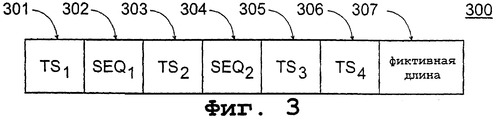
Фиг.3 иллюстрирует структуру пакета ИП, целесообразную для реализации одного варианта осуществления данного изобретения;Figure 3 illustrates the structure of the IP package, suitable for implementing one embodiment of the present invention;
Фиг.4 иллюстрирует пример пояснения одного варианта осуществления данного изобретения;4 illustrates an example of an explanation of one embodiment of the present invention;
Фиг.5 - схематическое представление временной области, иллюстрирующей пример, изображаемый на Фиг.4; иFigure 5 is a schematic representation of a time domain illustrating the example depicted in Figure 4; and
Фиг.6 иллюстрирует аппаратуру для реализации данного изобретения.6 illustrates apparatus for implementing the present invention.
Фиг.1 и 2 уже пояснялись выше в связи с описанием известного уровня техники. Далее поясняется предпочтительный вариант осуществления данного изобретения, при котором эмулируют вызов ИП между первым узлом сети и вторым узлом сети, и выполняют измерения КО. Фиг.1 также схематически иллюстрирует структуру выполнения измерения согласно данному изобретению. Согласно предпочтительному варианту осуществления данного изобретения первый узел 101 сети передает по сети 103 ИП на второй узел 102 сети аналогичный равномерный поток пакетов ИП, который формируют реалистичным кодеком, таким как G.711, при этом размеры пакетов ИП соответствуют размеру пакетов, формируемых реальным кодеком. Пакеты ИП предпочтительно передают с помощью ПДП в дополнение к ИП. Фиг.3 иллюстрирует структуру пакета ИП, который используют в предпочтительном варианте осуществления данного изобретения. Пакет 300 ИП содержит различные типы полей для запоминания информации, вводимой узлами сети в каждый пакет ИП в определенные моменты времени. В полях 301 и 302 каждого пакета ИП первый узел 101 сети непосредственно перед передачей каждого пакета 300 ИП запоминает в качестве первой информации данные TS1 отметки времени и данные SEQ1 порядкового номера пакета, соответственно. Например, при передаче первого пакета ИП первый узел сети запоминает в качестве данных TS1 отметки времени пакета ИП время передачи данного пакета ИП, а номер 1 - в качестве данных SEQ1 порядкового номера. Соответственно, в качестве данных TS1 отметки времени второго пакета ИП запоминают время передачи второго пакета ИП, а номер 2 - в качестве SEQ1 порядкового номера, и так далее.1 and 2 have already been explained above in connection with the description of the prior art. Next, a preferred embodiment of the present invention is explained in which an IP call is emulated between the first network node and the second network node, and QoS measurements are performed. Figure 1 also schematically illustrates the structure of the measurement according to this invention. According to a preferred embodiment of the present invention, the
При поступлении потока пакетов ИП во второй узел 102 сети: второй узел сети запоминает в полях 303 и 304 каждого пакета ИП данные TS2 отметки времени и данные SEQ2 порядкового номера пакетов, соответственно, в качестве второй информации. Когда первый пакет ИП (который не обязательно должен быть пакетом ИП, который был первым передан первым узлом сети) потока пакетов ИП прибывает во второй узел сети, второй узел сети затем запоминает время прибытия данного пакета ИП во втором узле сети как данные TS2 отметки времени данного пакета ИП, а номер 1 - в качестве данных SEQ2 порядкового номера. Соответственно, время прибытия второго пакета ИП во второй узел сети запоминают в качестве данных TS2 отметки времени данного пакета ИП, а номер 2 - в качестве порядкового номера SEQ2, и так далее.Upon receipt of the flow of IP packets to the second network node 102: the second network node stores in the
Но согласно данному изобретению пакеты ИП, поступающие во второй узел сети, не возвращаются немедленно в первый узел сети, а направляются (или их данные) в буфер во втором узле сети, откуда их затем передают в порядке прибытия назад в первый узел сети как аналогичный равномерный поток пакетов ИП по мере его формирования реалистичным кодеком, используемом в вызове ИП. Таким образом, асимметрию можно устранить путем передачи пакетов ИП лучшим образом, чем в решениях известного уровня техники. При передаче каждого буферизованного пакета ИП назад в первый узел сети второй узел сети запоминает в поле 305 каждого пакета ИП в качестве третьей информации данные ТS3 отметки времени. Время передачи каждого пакета ИП запоминают в качестве данных ТS3 отметки времени.But according to this invention, IP packets arriving at the second network node are not immediately returned to the first network node, but are sent (or their data) to a buffer in the second network node, from where they are then transferred in the order of arrival back to the first network node as a similar uniform IP packet stream as it is formed by a realistic codec used in the IP call. Thus, asymmetry can be eliminated by transmitting IP packets in a better way than in solutions of the prior art. When each buffered IP packet is transmitted back to the first network node, the second network node stores in the
При поступлении пакетов ИП потока пакетов ИП, вернувшихся из второго узла сети в первый узел сети, первый узел сети запоминает в поле 306 каждого пакета ИП данные TS4 отметки времени в качестве четвертой информации. Время поступления каждого пакета ИП в первый узел сети запоминают как данные TS4 отметки времени. Для указания последовательности, в которой пакеты ИП возвращаются в первый узел сети, новый индикатор номера последовательности (например, SEQ3) предпочтительно не требуется, если принятые пакеты ИП (или данные, содержащиеся в них) запоминают в той же последовательности, в какой они поступили в первый узел сети. Разумеется, также возможно использование индикатора SEQ3 порядкового номера в связи с данным изобретением.Upon receipt of IP packets of the IP packet stream returned from the second network node to the first network node, the first network node stores TS time data 4 as time information in the
Помимо полей 301-306 пакет 300 ИП согласно Фиг.3 содержит фиктивную длину 307. Фиктивная длина 307 является частью данных определенной длины, которая необязательно имеет какое-либо другое значение, кроме того, с которым длину пакета ИП можно согласовать с размером пакетов реалистичного кодека, такого как G.711. Помимо полей, изображаемых на Фиг. 3, пакет 300 ИП обычно содержит заголовки ИП и ПДП, помимо прочего, для адресной информации и номеров портов отправителя и получателя. Содержание полей 301-307 можно назвать “полезной нагрузкой”.In addition to fields 301-306, the
В числе параметров КО сквозную задержку drt двойного прохождения сигнала в прямом и обратном направлениях можно определить уравнением drt.new=TS4-TS1-(ТS3-TS2). Если генераторы синхроимпульсов первого и второго узлов сети синхронизированы, то сквозные задержки одинарного прохождения сигнала можно вычислить по уравнению dow.1=ТS2-TS1 (прохождение от второго узла сети к первому) и dow.2=TS4-ТS3 (обратное прохождение от второго узла сети к первому). При синхронизировании узлов сети можно использовать например, глобальную спутниковую систему определения местоположения абонента (GPS, ГССТ).Among the QoS parameters, the end-to-end delay d rt of double signal passage in the forward and reverse directions can be determined by the equation d rt.new = TS 4 -TS 1 - (TS 3 -TS 2 ). If the clock generators of the first and second network nodes are synchronized, then the end-to-end delays of a single signal passage can be calculated by the equation d ow.1 = TS 2 -TS 1 (passage from the second network node to the first) and d ow.2 = TS 4 -TS 3 (backward passage from the second network node to the first). When synchronizing network nodes, you can use, for example, a global satellite system for determining the location of a subscriber (GPS, GPS).
Материал для вычисления колебания сквозной задержки можно получить, например, путем подсчета разностей между отметками времени TS2 последовательных пакетов ИП, поступающих во второй узел сети. На основе этих разностей затем можно вычислить, например, среднеквадратическое отклонение и/или дисперсию колебания сквозной задержки (от первого узла сети во второй узел сети).Material for calculating the oscillation of the end-to-end delay can be obtained, for example, by counting the differences between the timestamps TS 2 of successive IP packets arriving at the second network node. Based on these differences, it is then possible to calculate, for example, the standard deviation and / or variance of the end-to-end delay oscillation (from the first network node to the second network node).
Затем можно выявить потери пакетов, если известно число передаваемых пакетов ИП. В этом случае, например, если поток пакетов ИП прошел дважды в прямом и обратном направлениях между первым и вторым узлами сети, то число пакетов, потерянных во время первой части, можно выявить вычитанием числа пакетов ИП, поступивших во второй узел сети, из числа переданных пакетов.Then, packet loss can be detected if the number of transmitted IP packets is known. In this case, for example, if the flow of IP packets passed twice in the forward and reverse directions between the first and second network nodes, the number of packets lost during the first part can be detected by subtracting the number of IP packets received at the second network node from the number transmitted packages.
Корреляцию потери пакетов (здесь от первого узла сети во второй узел сети) можно определить рассмотрением порядковых номеров SEQ1 пакетов ИП, принятых во втором узле сети, и за счет определения отсутствующих порядковых номеров.The correlation of packet loss (here from the first network node to the second network node) can be determined by considering the sequence numbers of SEQ 1 IP packets received at the second network node, and by determining the missing sequence numbers.
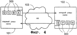
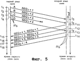
Далее реализация предпочтительного варианта осуществления данного изобретения рассматривается более подробно с помощью приводимого в качестве примера случая со ссылкой на Фиг.4 и 5, причем Фиг.4 изображает основную структуру приводимого в качестве примера случая, а Фиг.5 схематически изображает временную область для иллюстрирования приводимого в качестве примера случая. На Фиг.5 левая ось времени изображает время согласно генератору синхроимпульсов первого узла сети, а правая ось времени изображает время согласно генератору синхроимпульсов второго узла сети. Генераторы синхроимпульсов первого и второго узлов сети можно синхронизировать друг с другом.Next, the implementation of the preferred embodiment of the present invention is described in more detail using an example case with reference to Figs. 4 and 5, where Fig. 4 depicts the basic structure of an exemplary case and Fig. 5 schematically depicts a time domain for illustrating as an example of a case. 5, the left time axis represents time according to the clock generator of the first network node, and the right time axis represents time according to the clock generator of the second network node. The clock generators of the first and second network nodes can be synchronized with each other.
Предположим, что число передаваемых пакетов N=4. При передаче пакетов ИП эмулируют интервал передачи пакетов ИП, сформированных реалистичным кодеком - Δ tti. До измерений КО сообщение отправляют из первого узла сети во второй узел сети, при этом значения параметров N, Δ tti и буферную задержку Δ tbuf указывают второму узлу сети. Необходимо отметить, что хотя для упрощения число передаваемых пакетов N=4, практически число передаваемых пакетов ИП можно значительно увеличить, например, до нескольких сотен или тысяч.Suppose the number of transmitted packets is N = 4. When transmitting IP packets, they emulate the transmission interval of IP packets formed by a realistic codec - Δ t ti . Before measuring the QoS, the message is sent from the first network node to the second network node, while the values of the parameters N, Δ t ti and the buffer delay Δ t buf indicate the second network node. It should be noted that although to simplify the number of transmitted packets N = 4, practically the number of transmitted IP packets can be significantly increased, for example, to several hundred or thousands.
Передают поток ИП пакетов от первого узла сети 101 во второй узел сети 102, при этом в первом пакете ИП (пакет А) порядковый номер SEQ1=1, отметку TS1 времени запоминают непосредственно перед передачей данного пакета ИП в момент t1; во втором пакете ИП (пакет В) порядковый номер SEQ1=2 и отметку TS1 времени запоминают в момент t2; в третьем пакете ИП (пакет С) порядковый номер SEQ1=3 и отметку TS1 времени запоминают в момент t3; и в четвертом пакете ИП (пакет D) порядковый номер SEQ1=4 и отметку TS1 времени запоминают в момент t4. Пакеты ИП передают в интервалах Δ tti и поэтому t2-t1=Δ tti, t3-t2=Δ tti; t4-t3=Δ tti. Указанные моменты t1, t2, t3 и t4 даны согласно генератору синхроимпульсов первого узла сети.The stream of IP packets is transmitted from the first node of the
После приема сообщения от первого узла сети, в котором указывается число “четыре” количества передаваемых N пакетов ИП, второй узел сети запоминает в специальном (передающем) буфере четыре пакета ИП, порядковые номера которых: SEQ2=-1 (первый пакет ИП, передаваемый из буфера (пакет Е)); SEQ2=-2 (второй пакет (пакет F)); SEQ2=-3 (третий пакет (пакет G)); SEQ2=-4 (четвертый пакет (пакет Н));After receiving a message from the first network node, in which the number “four” of the number of transmitted N IP packets is indicated, the second network node stores four IP packets in a special (transmitting) buffer, the sequence numbers of which are: SEQ 2 = -1 (first IP packet transmitted from the buffer (packet E)); SEQ 2 = -2 (second packet (packet F)); SEQ 2 = -3 (third packet (packet G)); SEQ 2 = -4 (fourth packet (packet H));
После приема, в момент t5, первого из пакетов ИП, переданного первым узлом сети, который является пакетом ИП (пакетом А), также переданным первым (это не всегда так, например, если первый пакет ИП по пути потерян), второй узел сети запоминает в данном пакете ИП (пакет А) отметку TS2 времени и запоминает порядковый номер SEQ2=1. После этого второй узел сети копирует отметку времени и данные порядкового номера (TS1, SEQ1=1, TS2 и SEQ2=1) данного пакета ИП (пакет А) в пакете ИП (пакет Е), который в буфере является по очереди первым на передачу, после чего, помимо прочего, в пакете ИП, который в буфере является по очереди первым на передачу, порядковый номер (пакет Е) SEQ2=-1 заменяют на номер 1. Пакет Е теперь передают от второго узла сети в первый узел сети после буферной задержки Δ tbuf в момент t11=t5+Δ tbuf. Непосредственно перед передачей второй узел сети запоминает, в пакете Е, отметку TS3 времени. Это происходит приблизительно в момент t11.After receiving, at time t 5 , the first of the IP packets transmitted by the first network node, which is the IP packet (packet A), also transmitted by the first (this is not always the case, for example, if the first IP packet is lost along the way), the second network node remembers the time stamp TS 2 in this IP package (packet A) and remembers the sequence number SEQ 2 = 1. After that, the second network node copies the time stamp and serial number data (TS 1 , SEQ 1 = 1, TS 2 and SEQ 2 = 1) of this IP packet (packet A) in the IP packet (packet E), which in turn is in the buffer the first to be transmitted, after which, among other things, in the IP packet, which is the first to be transmitted in turn in the buffer, the sequence number (packet E) of SEQ 2 = -1 is replaced by
Когда начат поток возвращаемых пакетов ИП, другие три пакета ИП (пакеты F, G и Н), ожидают свою передачу в буфере второго узла сети в интервалах Δ tbuf в моменты времени t12; (пакет F), t13 (пакет G) и t14 (пакет Н), при этом, если для пакетов Е, F,G и Н используют номера индексов j=1, 2, 3, 4, соответственно, то время t1j передачи каждого пакета согласно генератору синхроимпульсов второго узла сети получают из уравнения t1j=t5+Δ tbuf+(j-1)Δ tti.When the flow of returned IP packets is started, the other three IP packets (packets F, G, and H) wait for their transmission in the buffer of the second network node in the intervals Δ t buf at time t 12 ; (packet F), t 13 (packet G) and t 14 (packet H), if index numbers j = 1, 2, 3, 4 are used for packets E, F, G, and H, respectively, then time t 1j, the transmission of each packet according to the clock generator of the second network node is obtained from the equation t 1j = t 5 + Δ t buf + (j-1) Δ t ti .
Соответственно, при приеме некоторого другого (отличного от упоминаемого выше пакета А) пакета ИП, относящегося к потоку пакетов ИП, отправленных от первого узла сети во второй узел сети, второй узел сети запоминает в принятом пакете отметку ТS2 времени и порядковый номер SEO2, после чего второй узел сети копирует данные принятого пакета ИП в таком пакете ИП в передающем буфере второго узла сети, который является следующим по очереди на его передачу, причем данные некоторых прибывших пакетов ИП еще не скопированы. Перед передачей каждого пакета ИП второй узел сети еще хранит в каждом подлежащем передаче пакете отметку ТS3 времени. Таким образом, в ситуации, иллюстрируемой на Фиг.4 и 5 после приема пакета В - второй узел сети запоминает в нем отметку TS2 времени в момент t6 и порядковый номер SEQ2=2, поскольку пакет В является вторым пакетом ИП, который прибывает во второй узел сети. Данные пакета В копируют в пакете F, ожидающем своей передачи в буфере, причем, помимо прочего, порядковый номер пакета F SEQ2=-2 заменяют на номер 2. Пакет F передают в момент t12. Непосредственно перед передачей отметку TS2 времени запоминают в пакете F.Accordingly, upon receipt of some other (different from the packet A mentioned above) IP packet related to the flow of IP packets sent from the first network node to the second network node, the second network node remembers the time stamp TS 2 and the SEO number 2 in the received packet, then the second network node copies the data of the received IP packet in such an IP packet in the transmit buffer of the second network node, which is the next in turn to transmit it, and the data of some arriving IP packets has not yet been copied. Before transmitting each IP packet, the second network node still stores a TS 3 time stamp in each packet to be transmitted. Thus, in the situation illustrated in FIGS. 4 and 5, after receiving packet B, the second network node remembers the time stamp TS 2 at time t 6 and the sequence number SEQ 2 = 2, since packet B is the second IP packet that arrives to the second network node. The data of packet B is copied in packet F, which is awaiting transmission in the buffer, and, among other things, the sequence number of packet F SEQ 2 = -2 is replaced by
Ситуация, при которой происходит потеря пакетов, рассматривается далее на примере, иллюстрируемом на Фиг.4 и 5. Предположим, что пакет С пропадает и не поступает во второй узел сети. Поскольку буферная задержка Δ tbuf в этом случае настолько длительная, что передаваемый следующим пакет (пакет D), тем не менее, все же прибывает во второй узел сети в момент t8 - до времени передачи пакета G t13=t5+Δ tbuf+2Δ tti (пакет G является пакетом, в котором для обратной передачи необходимо копировать данные пакета С), вместо потерянного пакета С в пакете G копируют данные пакета D (TS1, SEQ1=4, ТS2 и SEQ2=3), при этом, помимо прочего, порядковый номер пакета G SEQ2=-3 заменяют на номер 3. Пакет G передают в момент t13. Непосредственно перед передачей отметку ТS3 времени запоминают в пакете G.The situation in which packet loss occurs is considered further using the example illustrated in FIGS. 4 and 5. Assume that packet C disappears and does not arrive at the second network node. Since the buffer delay Δ t buf in this case is so long that the packet transmitted by the next one (packet D), however, nevertheless arrives at the second network node at time t 8 - before the packet transmission time G t 13 = t 5 + Δ t buf + 2Δ t ti (packet G is a packet in which it is necessary to copy the data of packet C for the reverse transmission), instead of the lost packet C, packet D data is copied in packet G (TS 1 , SEQ 1 = 4, TS 2 and SEQ 2 = 3 ), while, among other things, the sequence number of the packet G SEQ 2 = -3 is replaced by
Поскольку пакет С не поступил во второй узел сети, то нет пакета ИП, который поступил бы во второй узел сети и из которого данные уже были бы скопированы в некотором пакете, при этом копировать в пакете Н нечего. Для обеспечения равномерного потока пакетов ИП пакет Н, тем не менее, передают как т.н. фиктивный пакет (заполняющий пакет) в момент t14 передачи, хотя он в данное время не содержит значений, основанных на отметке реального времени и данных порядкового номера для TS1, SEQ1 и TS2. Перед передачей отметку TS3 времени запоминают в пакете Н. Поскольку новый порядковый номер SEQ2 не был скопирован и в пакете Н, то отрицательный порядковый номер SEQ2=-4 остается как порядковый номер пакета Н.Since the packet C did not arrive at the second node of the network, there is no IP packet that would arrive at the second node of the network and from which the data would have already been copied in some packet, and there is nothing to copy in the packet N. To ensure a uniform flow of IP packets, packet H, however, is transmitted as the so-called. the dummy packet (filling packet) at the time t 14 of the transmission, although it currently does not contain values based on the real-time stamp and serial number data for TS 1 , SEQ 1 and TS 2 . Before transmission, the TS 3 time stamp is stored in packet N. Since the new sequence number SEQ 2 was not copied in packet H, the negative sequence number SEQ 2 = -4 remains as the sequence number of packet N.
Когда пакеты Е, F, G и Н поступают в первый узел сети в моменты t15, t16, t17 и t18, соответственно, первый узел сети запоминает в них отметки TS4 времени. Для параметров КО значения теперь можно определить согласно излагаемому выше порядку. Если порядковый номер SEQ2 некоторого полученного пакета ИП отрицательный, то первый узел сети определит его как фиктивный пакет и при этом не будет учитывать информацию, которая, возможно, будет находиться в полях 301 (TS1), 302 (SEQ1) и/или 303 (TS2) фиктивного пакета, поскольку эта информация не основана на отметке реального времени или данных порядкового номера. Наличие фиктивных пакетов в возвращаемом потоке пакетов ИП обычно означает, что по меньшей мере один из пакетов ИП, первоначально переданный от первого узла сети на второй узел сети, не поступил на второй узел или поступил туда слишком поздно. В данном изобретении ошибочные ситуации, подобные этой, учитываются излагаемым выше образом (например, путем использования фиктивных пакетов), и эмуляция реалистичного вызова ИП и измерения КО будут удаваться, даже если произошли потери пакетов.When packets E, F, G, and H arrive at the first network node at times t 15 , t 16 , t 17, and t 18 , respectively, the first network node stores time marks TS 4 in them. For QoS parameters, the values can now be determined according to the order described above. If the sequence number SEQ 2 of some received IP packet is negative, then the first network node will determine it as a dummy packet and will not take into account information that may be in fields 301 (TS 1 ), 302 (SEQ 1 ) and / or 303 (TS 2 ) of the dummy packet because this information is not based on a real-time stamp or serial number data. The presence of dummy packets in the returned IP packet stream usually means that at least one of the IP packets originally transmitted from the first network node to the second network node did not arrive at the second node or arrived there too late. In the present invention, error situations such as this are taken into account in the manner described above (for example, by using dummy packets), and emulation of a realistic call of IP and measurement of QoS will succeed even if packet loss occurs.
В вызове ИП, когда передают речь в реальном времени, обычно происходят периоды интенсивного разговора и периоды молчания (паузы). Это объясняется тем, что когда одна сторона вызова ИП говорит, другая сторона обычно молчит. Для некоторых оконечных устройств РИП (оконечные устройства радиосвязи, телефоны) разработаны детекторы обнаружения речевой активности (ОРА), которые работают по следующему принципу: когда уровень речевого сигнала, поступающего в детектор ОРА, снижается ниже определенного уровня (говорящий молчит), пакеты ИП более не будут передаваться в сторону приема. В этом случае экономится полоса передачи данных.In an IP call, when voice is transmitted in real time, periods of intense conversation and periods of silence (pause) usually occur. This is because when one side of the IP call speaks, the other side is usually silent. For some RIP terminal devices (radio terminal devices, telephones), speech activity detection detectors (OPA) have been developed that operate according to the following principle: when the level of the speech signal entering the OPA detector decreases below a certain level (the speaker is silent), the IP packets no longer will be transmitted towards reception. In this case, the data bandwidth is saved.
Далее следует описание порядка эмуляции вызова ИП, согласно данному изобретению, для выполнения измерений КО, при этом стороны имеют в своих оконечных устройствах РИП функцию ОРА. Пакеты ИП передают от первого узла сети во второй узел сети по-прежнему в интервалах Δ tti, но после передачи Nts пакетов ИП делают паузу в передаче пакетов ИП, которая длится период Nsp Δ tti. После этого для Nts выделяют новое значение, и пакеты ИП передают в течение периода NtsΔ tti. Затем новое значение выделяют для Nsp, и снова делают паузу в передаче пакетов ИП на период NspΔ tti, и т.д. Фигуры Nts, Nsp выделяют из случайной функции распределения Р(Nts), Р(Nsp), соответственно, из числа которых P(Nts) эмулирует распределение длительностей интенсивного разговора, а P(Nsp) - распределение длительностей периодов молчания в реальном вызове ИП. Материал для формирования распределений Р(Nts), Р(Nsp) получают, например, путем измерения длительностей интенсивного разговора и пауз в реальных вызовах ИП.The following is a description of the procedure for emulating an IP call, according to this invention, for performing QoS measurements, while the parties have an OPA function in their RIP terminal devices. IP packets are transmitted from the first network node to the second network node as before in the intervals Δ t ti , but after the transmission of N ts IP packets, a pause is made in the transmission of IP packets, which lasts for a period of N sp Δ t ti . After that, a new value is allocated for N ts , and the IP packets are transmitted during the period N ts Δ t ti . Then a new value is allocated for N sp , and again pause in the transmission of IP packets for the period N sp Δ t ti , etc. The figures N ts , N sp are distinguished from the random distribution function P (N ts ), P (N sp ), respectively, from among which P (N ts ) emulates the distribution of durations of intensive conversation, and P (N sp ) - the distribution of durations of silence periods in a real call IP. Material for the formation of distributions P (N ts ), P (N sp ) is obtained, for example, by measuring the duration of intensive conversation and pauses in real calls of the IP.
На практике, значения Nts, Nsp можно выделить для каждого из периодов интенсивного разговора и периода молчания независимо друг от друга в первом и втором узлах сети. И поскольку информация о числе N передаваемых пакетов уже до начала измерений КО доставлена от первого узла сети во второй, то общее число пакетов ИП, передаваемых в обоих направлениях, будет равным. Либо значения Nts, Nsp можно выделить только в первом узле сети, и в этом случае передачу пакетов ИП, возвращаемых вторым узлом сети в первый узел сети, можно будет хронировать на тот период времени, когда пакеты ИП не поступают во второй узел сети. Поэтому в этом случае второй узел сети “слушает”, поступают ли пакеты ИП, и если не поступают, то второй узел сети начинает возвращение пакетов ИП, находящихся в буфере, в первый узел сети. На практике “слушание” можно реализовать, например, таким образом, что если пакеты ИП не поступили во второй узел сети в течение определенного срока (например, буферная задержка составляет Δ tbuf), то второй узел сети делает вывод о том, что в первом узле сети идет период молчания, и после этого он начинает возвращение пакетов ИП в первый узел сети.In practice, the values of N ts , N sp can be distinguished for each of the periods of intensive conversation and the period of silence independently from each other in the first and second nodes of the network. And since the information about the number N of transmitted packets before the start of QoS measurements was delivered from the first network node to the second, the total number of IP packets transmitted in both directions will be equal. Or, the values of N ts , N sp can be distinguished only in the first network node, and in this case, the transmission of IP packets returned by the second network node to the first network node can be booked for the period of time when the IP packets do not arrive at the second network node. Therefore, in this case, the second network node “listens” to see if the IP packets arrive, and if not, the second network node starts returning the IP packets in the buffer to the first network node. In practice, “listening” can be implemented, for example, in such a way that if IP packets have not arrived at the second network node within a certain period of time (for example, the buffer delay is Δ t buf ), then the second network node concludes that in the first the network node goes through a period of silence, and after that it starts returning IP packets to the first network node.
Данное описание сосредоточено на описании эмуляции вызова ИП и выполнении измерений КО вызова ИП. Поскольку в реальном вызове ИП ПДП используют, когда какие-либо повторные передачи и подтверждения отсутствуют, поэтому в данном описании они не упоминаются. Но при установлении вызова ИП необходимо использовать надежный протокол, и поэтому повторные передачи и подтверждения пакетов имеют значение. Хорошо известными протоколами РИП передачи сигналов являются помимо прочих, Н.323 и протокол инициирования сеанса (ПИС). Протоколы передачи сигналов обеспечивают возможность, например, во время установления вызова ИП, того, что оконечное устройство РИП (первый узел сети), которое делает вызов ИП, и оконечное устройство РИП (второй узел сети), которое отвечает на вызов РИП, могут сообщать друг другу тип кодека, используемого каждой стороной. Например, в Н.323 передача сигналов, используемая во время установления вызова, большей частью происходит с помощью надежного протокола, ПУПД. Согласно данному изобретению установление вызова ИП эмулируют путем отправки одного или нескольких пакетов ИП от первого узла сети во второй узел сети в зависимости от эмулируемого протокола передачи сигналов. Указанный пакет ИП, используемый для эмуляции установления вызова, в других отношениях аналогичен описываемому выше пакету 300 ИП, но вместо заголовка ПДП он содержит заголовок ПУПД. Таким образом, во время эмуляции установления вызова пакеты ИП предпочтительно передают с помощью ПУПД по ИП. Заголовок ПУП обычно содержит, помимо прочего, информацию, которую можно использовать при передаче потерянных пакетов ИП.This description focuses on the description of the emulation of the call IP and the measurement of QoS call IP. Since in a real call, IP PDPs are used when there are no retransmissions and confirmations, therefore they are not mentioned in this description. But when establishing an IP call, it is necessary to use a reliable protocol, and therefore retransmissions and packet acknowledgments are important. Well-known RIP signaling protocols are, among others, H.323 and the session initiation protocol (SIP). Signaling protocols provide the possibility, for example, during the establishment of an IP call, that the RIP terminal (the first network node), which makes the IP call, and the RIP terminal (the second network node), which answers the RIP call, can communicate with each other A friend is the type of codec used by each side. For example, in H.323, the signaling used during call setup is mostly done using a reliable protocol, the PDP. According to the present invention, an IP call establishment is emulated by sending one or more IP packets from a first network node to a second network node, depending on the emulated signaling protocol. The specified IP packet used to simulate a call setup is, in other respects, similar to the
При эмуляции установления вызова всегда после приема пакета ИП, переданного первым узлом сети, второй узел сети немедленно передает этот же пакет назад в первый узел сети. Теперь можно измерить время установления вызова, которое является временем, истекшим с момента передачи первого пакета ИП до приема последнего пакета ИП на первом узле сети. Либо можно передать от первого узла сети только один пакет ИП и ждать его возвращения из второго узла сети. Когда вернувшийся пакет ИП будет принят в первом узле сети, тогда время установления вызова можно будет приблизительно определить путем умножения времени, истекшего между передачей пакета ИП и приемом вернувшегося пакета ИП, например, на некоторое соответствующее число. При определении времени установления вызова отметки TS2, ТS3 времени совсем не обязательны, поскольку пакет ИП передают назад сразу после прибытия во второй узел сети. Время между передачей пакета ИП и приемом вернувшегося пакета ИП определяют вычитанием отметки TS1 из отметки TS4 времени.When emulating a call setup, always after receiving an IP packet transmitted by the first network node, the second network node immediately transmits the same packet back to the first network node. Now you can measure the call setup time, which is the time elapsed from the moment the first IP packet was transmitted until the last IP packet was received at the first network node. Or you can transfer from the first network node only one IP packet and wait for it to return from the second network node. When the returned IP packet is received at the first node of the network, then the call setup time can be approximately determined by multiplying the time elapsed between the transmission of the IP packet and reception of the returned IP packet, for example, by some corresponding number. In determining the call setup time stamp TS 2, TS 3, the time is not entirely necessary, as IP packet is transmitted back immediately after the arrival of the second network node. The time between transmitting the IP packet and receiving the returned IP packet is determined by subtracting the TS 1 mark from the TS4 time stamp.
Разумеется, фактическая эмуляция вызова ИП и измерений КО вызова ИП начнется только после завершения эмуляции передачи сигналов, относящихся к установлению вызова.Of course, the actual emulation of the call of the IP and measurements of the QoS of the call of the IP will begin only after the completion of the emulation of the transmission of signals related to the establishment of the call.
Фиг.6 иллюстрирует аппаратуру, подходящую для реализации данного изобретения. Аппаратура содержит первый узел 101 сети и второй узел 102 сети и также сеть 103 ИП между узлами. Основными узлами могут быть, например ПК, подключенные к сети 103 ИП с помощью карты доступа к сети (здесь не изображена). Первый и второй узлы содержат главный бок управления (ГБУ), управляющий узлом сети, и также запоминающее устройство (ЗУ). ГБУом может быть, например, микропроцессор. Блоки 701-709 являются функциональными блоками, причем ГБУ выполнен с возможностью выполнения определенных действий на основе программы, содержащейся в ЗУ узла сети. В блоке 701 данные TS1 отметки времени запоминают в передаваемых пакетах ИП в соответствии с генератором синхроимпульсов (ГСИ) первого узла сети непосредственно перед передачей и данные SEQ1 порядкового номера. В блоке 702 пакеты ИП передают во второй узел 102 сети по сети 103 ИП. В блоке 705 второй узел 102 сети принимает пакеты ИП, передаваемые первым узлом 101 сети, при этом в блоке 706 данные TS2 отметки времени запоминают согласно генератору синхроимпульсов ГСИ системы и данным SEQ2 порядкового номера. В блоке 707 данные отметки времени и порядкового номера принятых пакетов ИП-TS1, SEQ1 TS2, SEQ2 копируют в пакетах ИП, ожидающих своей передачи в буфере. В блоке 708 данные ТS3 отметки времени запоминают в пакетах ИП, передаваемых в первый узел сети согласно генератору синхроимпульсов ГСИ второго узла сети непосредственно перед передачей. В блоке 709 пакеты ИП передают в первый узел 101 сети по сети 103 ИП. В блоке 703 первый узел сети принимает пакеты ИП, переданные вторым узлом 102 сети, при этом в блоке 704 данные TS4 отметки времени запоминают согласно генератору синхроимпульсов ГСИ первого узла сети.6 illustrates apparatus suitable for implementing the present invention. The apparatus comprises a
В запоминающем устройстве ЗУ узлов сети имеется область памяти, в которой ГБУ обычно запоминает содержание каждого передаваемого пакета ИП (данные отметки времени и порядкового номера). Таким образом, при передаче пакета ИП именно это содержание области памяти посылают стороне приема. Указанная область памяти означает, например, буфер в указанном втором узле сети, в котором пакеты ИП ожидают своей передачи в первый узел сети. На стороне приема ГБУ запоминает данные принимаемых пакетов ИП в своем запоминающем устройстве в файле для последующего анализа, например для вычисления параметров КО.In the storage device of the memory of the network nodes, there is a memory area in which the GBU usually remembers the contents of each transmitted IP packet (time stamp and serial number data). Thus, when transmitting the IP packet, it is this content of the memory area that is sent to the receiving side. The specified memory area means, for example, a buffer in the specified second network node, in which IP packets are waiting for their transmission to the first network node. On the receiving side, the GBU stores the data of the received IP packets in its storage device in a file for subsequent analysis, for example, to calculate the QoS parameters.
Таким образом, существенные части данного изобретения можно реализовать средствами программного обеспечения. Соответствующие компьютерные программы, хранящиеся в запоминающих устройствах ЗУ узлов сети, можно программировать соответствующим для этих целей языком программирования, таким как язык программирования С.Thus, the essential parts of this invention can be implemented by software. Corresponding computer programs stored in memory devices of network nodes memory can be programmed with a programming language, such as programming language C.
Поскольку данное изобретение предлагает средство для более точной эмуляции реалистичного вызова ИП на уровне применения с сигналопередающими и симметричными равномерными потоками пакетов ИП по сравнению с известными решениями уровня техники, данное изобретение обеспечивает возможность выполнения измерений КО вызова ИП более надежным образом, чем известные решения. В устройстве согласно данному изобретению ошибочные ситуации сети ИП также предусмотрены, согласно данному изобретению можно также выполнять надежные измерения КО, когда пакеты ИП вызова ИП теряются по пути или когда поступают к получателю слишком поздно.Since this invention provides a means for more accurate emulation of a realistic IP call at the application level with signal-transmitting and symmetric uniform flows of IP packets in comparison with the known solutions of the prior art, this invention provides the possibility of performing QoS measurements of an IP call in a more reliable way than the known solutions. In the device according to this invention, IP network error situations are also provided, according to this invention it is also possible to perform reliable QoS measurements when IP call IP packets are lost along the way or when they arrive at the recipient too late.
Несмотря на то, что в данном описании описывается устройство, содержащее два узла сети и сеть с коммутацией пакетов между ними, в практических случаях может присутствовать большее число узлов. Так, от первого узла сети поток пакетов ИП можно передать в два или более вторых узла сети, которые все будут возвращать пакеты ИП, переданные первым узлом сети. Например, таким образом возможно эмулировать групповой вызов ИП, который выполняют из одного оконечного устройства РИП, в два, или более оконечных устройств РИП, и также можно сделать соответствующие измерения КО. Также согласно данному изобретению обеспечивают возможность эмуляции более одного вызова ИП одновременно или неодновременно, и, таким образом возможность выполнения измерения КО с помощью нескольких разных пар узлов сети.Despite the fact that this description describes a device containing two network nodes and a network with packet switching between them, in practical cases, a larger number of nodes may be present. So, from the first network node, the packet flow of IP packets can be transmitted to two or more second network nodes, which will all return IP packets transmitted by the first network node. For example, in this way it is possible to emulate a group call of an IP that is performed from one RIP terminal device into two or more RIP terminal devices, and it is also possible to make corresponding QoS measurements. Also, according to this invention, it is possible to emulate more than one IP call at the same time or at the same time, and thus the ability to perform QoS measurements using several different pairs of network nodes.
Данное описание представляет реализацию и варианты осуществления данного изобретения с помощью иллюстрируемых примеров. Для специалиста в данной области техники будет очевидно, что данное изобретение не ограничивается подробностями излагаемых выше вариантов осуществления и что данное изобретение можно также реализовать в другом виде в рамках признаков изобретения. Описываемые выше варианты осуществления следует рассматривать как иллюстративные, а не ограничивающие. Поэтому возможности реализации и использования данного изобретения ограничиваются только прилагаемой формулой изобретения. Следовательно, различные варианты реализации изобретения, определяемого формулой изобретения, включая эквивалентные реализации, также относятся к объему данного изобретения.This description represents the implementation and embodiments of the present invention using illustrated examples. It will be apparent to those skilled in the art that the invention is not limited to the details of the above embodiments, and that the invention can also be implemented in another form within the scope of the features of the invention. The embodiments described above should be considered as illustrative and not restrictive. Therefore, the possibilities for implementing and using the present invention are limited only by the attached claims. Therefore, various embodiments of the invention defined by the claims, including equivalent implementations, also fall within the scope of this invention.
Claims (16)
Applications Claiming Priority (2)
| Application Number | Priority Date | Filing Date | Title |
|---|---|---|---|
| FI20000316 | 2000-02-14 | ||
| FI20000316A FI20000316A (en) | 2000-02-14 | 2000-02-14 | Emulation of information flow |
Publications (2)
| Publication Number | Publication Date |
|---|---|
| RU2002124604A RU2002124604A (en) | 2004-02-10 |
| RU2249305C2 true RU2249305C2 (en) | 2005-03-27 |
Family
ID=8557492
Family Applications (1)
| Application Number | Title | Priority Date | Filing Date |
|---|---|---|---|
| RU2002124604/09A RU2249305C2 (en) | 2000-02-14 | 2001-01-15 | Method for data stream emulation |
Country Status (15)
| Country | Link |
|---|---|
| US (1) | US7274714B2 (en) |
| EP (1) | EP1256200B1 (en) |
| JP (1) | JP2003523132A (en) |
| KR (1) | KR100448280B1 (en) |
| CN (1) | CN1240199C (en) |
| AT (1) | ATE349827T1 (en) |
| AU (1) | AU2853501A (en) |
| BR (1) | BR0108329A (en) |
| CA (1) | CA2399056A1 (en) |
| DE (1) | DE60125512T2 (en) |
| ES (1) | ES2278760T3 (en) |
| FI (1) | FI20000316A (en) |
| MX (1) | MXPA02007832A (en) |
| RU (1) | RU2249305C2 (en) |
| WO (1) | WO2001059981A1 (en) |
Families Citing this family (20)
| Publication number | Priority date | Publication date | Assignee | Title |
|---|---|---|---|---|
| CA2351175C (en) * | 1998-11-24 | 2016-05-03 | Niksun, Inc. | Apparatus and method for collecting and analyzing communications data |
| FI20001578A (en) | 2000-06-30 | 2001-12-31 | Nokia Networks Oy | QoS architecture |
| US8218555B2 (en) * | 2001-04-24 | 2012-07-10 | Nvidia Corporation | Gigabit ethernet adapter |
| US20070253430A1 (en) * | 2002-04-23 | 2007-11-01 | Minami John S | Gigabit Ethernet Adapter |
| US7437463B1 (en) * | 2002-06-21 | 2008-10-14 | Polycom, Inc. | Method and means for providing scheduling for a videoconferencing network in a manner to ensure bandwidth |
| US8176545B1 (en) | 2003-12-19 | 2012-05-08 | Nvidia Corporation | Integrated policy checking system and method |
| US8442506B2 (en) * | 2004-07-23 | 2013-05-14 | Gregory Peacock | System and method for communications in a multi-platform environment |
| US8036123B1 (en) | 2005-01-07 | 2011-10-11 | Marvell International Ltd. | Integrated circuit for network stress testing |
| US8054826B2 (en) * | 2005-07-29 | 2011-11-08 | Alcatel Lucent | Controlling service quality of voice over Internet Protocol on a downlink channel in high-speed wireless data networks |
| US8797870B2 (en) * | 2006-01-05 | 2014-08-05 | Cisco Technology, Inc. | Method and system for calculation of QOV metrics |
| US8472371B1 (en) | 2007-02-21 | 2013-06-25 | At&T Mobility Ii Llc | Roaming support for wireless access subscriber over fixed IP access networks |
| CN101330700B (en) * | 2007-06-19 | 2012-02-29 | 中兴通讯股份有限公司 | Method for scheduling ascending IP load-bearing voice service |
| JP2010074227A (en) * | 2008-09-16 | 2010-04-02 | Fuji Xerox Co Ltd | Information processing system, communication control device and program |
| US8578020B2 (en) | 2009-12-24 | 2013-11-05 | Empire Technology Development Llc | Dynamic mobile application quality-of-service monitoring and reporting |
| US9191696B2 (en) * | 2012-06-15 | 2015-11-17 | Samsung Electronics Co., Ltd. | Reception device and program for reception device |
| US9602383B2 (en) | 2012-10-11 | 2017-03-21 | Telefonaktiebolaget Lm Ericsson (Publ) | General packet radio service tunnel performance monitoring |
| US9338678B2 (en) * | 2012-10-11 | 2016-05-10 | Telefonaktiebolaget Lm Ericsson (Publ) | Performance monitoring of control and provisioning of wireless access points (CAPWAP) control channels |
| CN103532931B (en) * | 2013-09-24 | 2017-01-25 | 北京星网锐捷网络技术有限公司 | Method and system for testing transmission performance of data stream, and server |
| US9300565B2 (en) * | 2014-04-17 | 2016-03-29 | Accedian Networks Inc. | System and method for out-of-line real-time in-service performance measurement |
| US11494101B2 (en) * | 2020-10-14 | 2022-11-08 | Western Digital Technologies, Inc. | Storage system and method for time-duration-based efficient block management and memory access |
Family Cites Families (9)
| Publication number | Priority date | Publication date | Assignee | Title |
|---|---|---|---|---|
| US5450394A (en) * | 1994-03-10 | 1995-09-12 | Northern Telecom Limited | Delay monitoring of telecommunication networks |
| WO1997003508A1 (en) * | 1995-07-13 | 1997-01-30 | Sony Corporation | Data transmission method, data transmission apparatus and data transmission system |
| EP0910194A2 (en) | 1997-09-24 | 1999-04-21 | At&T Wireless Services, Inc. | Network test system |
| US6587985B1 (en) | 1998-11-30 | 2003-07-01 | Matsushita Electric Industrial Co., Ltd. | Data transmission method, data transmission apparatus, data receiving apparatus, and packet data structure |
| EP1075129A1 (en) | 1999-08-06 | 2001-02-07 | BRITISH TELECOMMUNICATIONS public limited company | Test method for computer telephony |
| US6577648B1 (en) * | 1999-10-04 | 2003-06-10 | Nokia Corporation | Method and apparatus for determining VoIP QoS characteristics of a network using multiple streams of packets and synchronizing measurements of the streams |
| US6731649B1 (en) * | 2000-07-26 | 2004-05-04 | Rad Data Communication Ltd. | TDM over IP (IP circuit emulation service) |
| US7016340B1 (en) * | 2001-10-26 | 2006-03-21 | General Bandwidth Inc. | System and method for testing a voice gateway |
| US7010595B2 (en) * | 2001-12-14 | 2006-03-07 | D-Link Corp. | Apparatus for multi-level loopback test in a community network system and method therefor |
-
2000
- 2000-02-14 FI FI20000316A patent/FI20000316A/en unknown
-
2001
- 2001-01-15 WO PCT/FI2001/000033 patent/WO2001059981A1/en active IP Right Grant
- 2001-01-15 EP EP01951195A patent/EP1256200B1/en not_active Expired - Lifetime
- 2001-01-15 AT AT01951195T patent/ATE349827T1/en not_active IP Right Cessation
- 2001-01-15 AU AU28535/01A patent/AU2853501A/en not_active Abandoned
- 2001-01-15 CA CA002399056A patent/CA2399056A1/en not_active Abandoned
- 2001-01-15 DE DE60125512T patent/DE60125512T2/en not_active Expired - Fee Related
- 2001-01-15 CN CNB018049435A patent/CN1240199C/en not_active Expired - Fee Related
- 2001-01-15 ES ES01951195T patent/ES2278760T3/en not_active Expired - Lifetime
- 2001-01-15 JP JP2001559189A patent/JP2003523132A/en not_active Abandoned
- 2001-01-15 KR KR10-2002-7010635A patent/KR100448280B1/en not_active IP Right Cessation
- 2001-01-15 RU RU2002124604/09A patent/RU2249305C2/en not_active IP Right Cessation
- 2001-01-15 BR BR0108329-5A patent/BR0108329A/en not_active IP Right Cessation
- 2001-01-15 US US10/204,107 patent/US7274714B2/en not_active Expired - Fee Related
- 2001-01-15 MX MXPA02007832A patent/MXPA02007832A/en not_active Application Discontinuation
Also Published As
| Publication number | Publication date |
|---|---|
| ES2278760T3 (en) | 2007-08-16 |
| KR100448280B1 (en) | 2004-09-10 |
| FI20000316A0 (en) | 2000-02-14 |
| CN1240199C (en) | 2006-02-01 |
| RU2002124604A (en) | 2004-02-10 |
| FI20000316A (en) | 2001-08-15 |
| DE60125512D1 (en) | 2007-02-08 |
| US7274714B2 (en) | 2007-09-25 |
| KR20020077460A (en) | 2002-10-11 |
| WO2001059981A1 (en) | 2001-08-16 |
| BR0108329A (en) | 2003-03-11 |
| US20030108033A1 (en) | 2003-06-12 |
| MXPA02007832A (en) | 2002-10-23 |
| CA2399056A1 (en) | 2001-08-16 |
| AU2853501A (en) | 2001-08-20 |
| EP1256200B1 (en) | 2006-12-27 |
| DE60125512T2 (en) | 2007-08-02 |
| CN1401170A (en) | 2003-03-05 |
| ATE349827T1 (en) | 2007-01-15 |
| JP2003523132A (en) | 2003-07-29 |
| EP1256200A1 (en) | 2002-11-13 |
Similar Documents
| Publication | Publication Date | Title |
|---|---|---|
| RU2249305C2 (en) | Method for data stream emulation | |
| Bolot | Characterizing end-to-end packet delay and loss in the internet | |
| US6512761B1 (en) | System for adjusting billing for real-time media transmissions based on delay | |
| US7746797B2 (en) | Non-intrusive monitoring of quality levels for voice communications over a packet-based network | |
| US7372844B2 (en) | Call routing method in VoIP based on prediction MOS value | |
| US6360271B1 (en) | System for dynamic jitter buffer management based on synchronized clocks | |
| US20050094628A1 (en) | Optimizing packetization for minimal end-to-end delay in VoIP networks | |
| US6868094B1 (en) | Method and apparatus for measuring network data packet delay, jitter and loss | |
| KR100716153B1 (en) | Method for Measuring Stage-to-stage Delay in Nonsynchronization Packet Transfer Network, Nonsynchronization Packet Sender and Receiver | |
| JP2004129250A (en) | System and method of calculating reciprocating delay time of real-time protocol packet streams | |
| US20050174947A1 (en) | Method and process for video over IP network management | |
| US20020057686A1 (en) | Response time measurement for adaptive playout algorithms | |
| US6791987B1 (en) | Maintaining synchronization over asynchronous interface | |
| Seger | Modelling approach for VoIP traffic aggregations for transferring tele-traffic trunks in a QoS enabled IP-backbone environment | |
| Yletyinen | The quality of voice over ip | |
| Xu | Packet voice over non-QoS networks. | |
| Nakkhongkham | Measuring the quality of service of voice over IP | |
| Prasad et al. | A Holistic Study of VoIP Session Quality-The Knobs that Control | |
| Gao | Real-time Transmission Over Internet | |
| Darmani | Lost VOIP packet recovery in active networks. | |
| OäEGOVIĆ et al. | WTFC BASED INTEGRATION OF VOICE AND DATA TRAFFIC | |
| Knezevic et al. | ANALYSIS OF SOME QUALITY OF SERVICE PARAMETERS'IMPACT ON END-TO-END DELAY MEASUREMENTS IN VOIP NETWORK | |
| SECTOR et al. | CAUTION! PREPUBLISHED RECOMMENDATION | |
| PEZELJ et al. | WTFC BASED INTEGRATION OF VOICE AND DATA TRAFFIC | |
| Peuhkuri | Application and TCP measurements |
Legal Events
| Date | Code | Title | Description |
|---|---|---|---|
| MM4A | The patent is invalid due to non-payment of fees |
Effective date: 20100116 |