RU2248309C2 - Cover for flying vehicle engine nozzle - Google Patents
Cover for flying vehicle engine nozzle Download PDFInfo
- Publication number
- RU2248309C2 RU2248309C2 RU2003110205/11A RU2003110205A RU2248309C2 RU 2248309 C2 RU2248309 C2 RU 2248309C2 RU 2003110205/11 A RU2003110205/11 A RU 2003110205/11A RU 2003110205 A RU2003110205 A RU 2003110205A RU 2248309 C2 RU2248309 C2 RU 2248309C2
- Authority
- RU
- Russia
- Prior art keywords
- nozzle
- disk
- cover
- handle
- axle
- Prior art date
Links
Images
Landscapes
- Closures For Containers (AREA)
Abstract
Description
Изобретение относится к авиации, в частности к устройствам для наземного обслуживания самолета, и может быть использовано для защиты двигателей летательных аппаратов от попадания посторонних предметов во время стоянки.The invention relates to aviation, in particular to devices for ground handling of aircraft, and can be used to protect aircraft engines from the ingress of foreign objects during parking.
Самым близким аналогом является заглушка сопла двигателя летательного аппарата, содержащая обечайку и днище, снабженная фиксаторами, каждый из которых выполнен в виде резьбовой тяги с гайкой и поворотного упора, шарнирно соединенного с тягой и днищем, при этом по периметру обечайки образован жесткий фланец швеллерного сечения (Патент № 2063368, МКИ В 65 F 5/00).The closest analogue is the cap of the nozzle of the aircraft engine, containing a shell and a bottom, equipped with clamps, each of which is made in the form of a threaded rod with a nut and a rotary stop pivotally connected to the rod and bottom, while a rigid channel flange is formed around the circumference of the shell ( Patent No. 2063368, MKI B 65 F 5/00).
Недостатками прототипа является сложность конструкции и неудобство эксплуатации заглушки. Процесс установки занимает довольно много времени, т.к. гайки сначала выворачивают, затем вдвигают заглушку в сопло на достаточно большую глубину, заворачивают гайки и стопорят их контргайкой с проволокой.The disadvantages of the prototype is the design complexity and inconvenience of operation of the stub. The installation process takes a lot of time, because the nuts are first turned out, then the plug is inserted into the nozzle to a sufficiently large depth, the nuts are wrapped and locked with a lock nut with wire.
Технический результат, достигаемый при использовании изобретения заключается в упрощении конструкции и упрощении и удобстве эксплуатации.The technical result achieved by using the invention is to simplify the design and simplify and ease of operation.
Указанный технический результат достигается тем, что заглушка на сопло двигателя летательного аппарата содержит диск с фланцем по периметру и, по крайней мере, два поворотных упора, каждый из которых установлен на диске, причем каждый упор выполнен в виде эксцентрического ролика, жестко закрепленного на оси рукоятки, установленной с возможностью поворота и фиксации ролика в прижатом к поверхности сопла положении.The specified technical result is achieved by the fact that the plug on the nozzle of the aircraft engine contains a disk with a flange around the perimeter and at least two rotary stops, each of which is mounted on the disk, and each stop is made in the form of an eccentric roller rigidly fixed to the axis of the handle mounted with the possibility of rotation and fixation of the roller in the position pressed against the surface of the nozzle.
Каждая ось установлена во втулке, закрепленной на диске, и снабжена рукояткой с фиксатором, расположенным в ответном пазу на втулке. Заглушка снабжена стопором, выполненным в виде винта, пропущенного через втулку с возможностью взаимодействия с осью. Эксцентрические ролики выполнены с наружной поверхностью, эквидистантной внутренней поверхности сопла двигателя. Предлагаемая заглушка имеет простую конструкцию, удобна в эксплуатации, обеспечивает герметичность крепления, что предохраняет сопло от попадания посторонних предметов.Each axis is installed in the sleeve mounted on the disk and is equipped with a handle with a latch located in the mating groove on the sleeve. The cap is equipped with a stopper made in the form of a screw passed through the sleeve with the possibility of interaction with the axis. The eccentric rollers are made with the outer surface, the equidistant inner surface of the engine nozzle. The proposed plug has a simple design, easy to use, provides a tight seal, which protects the nozzle from foreign objects.
При исследовании изобретательского уровня не обнаружены технические решения с совокупностью признаков, обеспечивающих достижение указанного технического результата.In the study of the inventive step, no technical solutions were found with a combination of features ensuring the achievement of the specified technical result.
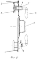
Сущность изобретения поясняется чертежом.The invention is illustrated in the drawing.
На фиг.1 изображен общий вид заглушки, на фиг.2 - вид слева.Figure 1 shows a General view of the stub, figure 2 is a left view.
Заглушка представляет собой диск 1 с фланцем 2 по периметру, выполненным из эластичного материала. На диске установлены два поворотных упора, каждый из которых выполнен в виде эксцентрического ролика 3, жестко закрепленного на оси 4, установленной с возможностью поворота и фиксации ролика 3 в прижатом к поверхности сопла положении. Каждая ось размещена во втулке 5, закрепленной на диске, и снабжена рукояткой 6 с фиксатором 7 и ответным пазом на втулке 5. В центре заглушки закреплена ручка 8. Для исключения самопроизвольного выпадения заглушка снабжена стопором, выполненным в виде винта 9, пропущенного через втулку 5 с возможностью взаимодействия с осью 4. Эксцентрические ролики 3 выполнены с наружной поверхностью, эквидистантной внутренней поверхности сопла двигателя.The cap is a disk 1 with a
Заглушка работает следующим образом.The stub works as follows.
Для установки заглушки в сопло ее берут за ручку 8, поворачивают рукоятки 6 в положении “открыто”, затем закрывают сопло диском и поворачивают рукоятки в положение “закрыто”. При повороте рукояток вместе с ними поворачиваются оси 4 с закрепленными на них эксцентрическими роликами 3. При этом ролики плотно прилегают поверхностью с большим радиусом эксцентрика к внутренней поверхности сопла, а фиксаторы 7 препятствуют прокручиванию осей 4. Положение “закрыто” фиксируется винтом 9, снятие заглушки происходит в обратной последовательности.To install the plug in the nozzle, take it by the
Claims (4)
Priority Applications (1)
| Application Number | Priority Date | Filing Date | Title |
|---|---|---|---|
| RU2003110205/11A RU2248309C2 (en) | 2003-04-09 | 2003-04-09 | Cover for flying vehicle engine nozzle |
Applications Claiming Priority (1)
| Application Number | Priority Date | Filing Date | Title |
|---|---|---|---|
| RU2003110205/11A RU2248309C2 (en) | 2003-04-09 | 2003-04-09 | Cover for flying vehicle engine nozzle |
Publications (2)
| Publication Number | Publication Date |
|---|---|
| RU2003110205A RU2003110205A (en) | 2004-11-20 |
| RU2248309C2 true RU2248309C2 (en) | 2005-03-20 |
Family
ID=35454325
Family Applications (1)
| Application Number | Title | Priority Date | Filing Date |
|---|---|---|---|
| RU2003110205/11A RU2248309C2 (en) | 2003-04-09 | 2003-04-09 | Cover for flying vehicle engine nozzle |
Country Status (1)
| Country | Link |
|---|---|
| RU (1) | RU2248309C2 (en) |
Citations (4)
| Publication number | Priority date | Publication date | Assignee | Title |
|---|---|---|---|---|
| US3754726A (en) * | 1970-07-10 | 1973-08-28 | Sarmac Sa | Assembly comprising a self-propelled finned projectile and its case |
| SU455043A1 (en) * | 1973-04-20 | 1974-12-30 | Куйбышевский Филиал Машиностроительного Конструкторского Бюро | Cap |
| RU2063368C1 (en) * | 1993-07-08 | 1996-07-10 | Акционерное общество открытого типа "Авиационный комплекс им.С.В.Ильюшина" | Flying vehicle engine nozzle cover |
| RU93034468A (en) * | 1993-07-08 | 1996-10-20 | Авиационный комплекс им.С.В.Ильюшина | Stub |
-
2003
- 2003-04-09 RU RU2003110205/11A patent/RU2248309C2/en not_active IP Right Cessation
Patent Citations (4)
| Publication number | Priority date | Publication date | Assignee | Title |
|---|---|---|---|---|
| US3754726A (en) * | 1970-07-10 | 1973-08-28 | Sarmac Sa | Assembly comprising a self-propelled finned projectile and its case |
| SU455043A1 (en) * | 1973-04-20 | 1974-12-30 | Куйбышевский Филиал Машиностроительного Конструкторского Бюро | Cap |
| RU2063368C1 (en) * | 1993-07-08 | 1996-07-10 | Акционерное общество открытого типа "Авиационный комплекс им.С.В.Ильюшина" | Flying vehicle engine nozzle cover |
| RU93034468A (en) * | 1993-07-08 | 1996-10-20 | Авиационный комплекс им.С.В.Ильюшина | Stub |
Similar Documents
| Publication | Publication Date | Title |
|---|---|---|
| US6273658B1 (en) | Enclosure for protecting a lug and lug nut | |
| US5444897A (en) | Hooks reciprocable between a recessed inoperative position and an exposed operative position | |
| CA2127974A1 (en) | Catch basin structure for interception of contaminants | |
| US4171851A (en) | Wheel cover locking device | |
| FR2698597A1 (en) | Steering lock for vehicles. | |
| CN110552373B (en) | Rotary manhole cover anti-theft mechanism and operation method | |
| FR3021934A3 (en) | REINFORCED TIRE VALVE OF A TIRE PRESSURE MEASURING DEVICE | |
| EP1064157B1 (en) | Lockable hubcap | |
| CN210821636U (en) | Protective sealing hub | |
| EP3941293B1 (en) | Anti-theft device for a helmet for a two-wheeled vehicle | |
| RU2063368C1 (en) | Flying vehicle engine nozzle cover | |
| WO1995031312A1 (en) | Open-end wrench with alternating rotation control | |
| FR2459159A1 (en) | STEERING LATCH ANTI-THEFT DEVICE FOR MOTOR VEHICLES | |
| DE2854700A1 (en) | SPARK PLUG LOCK | |
| JPS6030561B2 (en) | car tire wheel lock | |
| CN220350487U (en) | Wine bottle cap opened by auxiliary opening assembly | |
| CN223446816U (en) | Self-locking mechanism for bicycle frame | |
| EP1519461B1 (en) | Box, particularly for electrical devices | |
| CN221851913U (en) | Combined subway hanging ring | |
| CN219864560U (en) | Engineering vehicle door large torque rotary handle security lock | |
| EP2404790B1 (en) | Wheel clamp and methods of use | |
| FR2752764A1 (en) | Key for connecting domestic gas bottle to gas pipe | |
| US5896891A (en) | Wrap cap | |
| EP0923165B1 (en) | Device for preventing loss of anchoring sleeve of a conduit | |
| JPS5822455Y2 (en) | Packing attachment device for valves |
Legal Events
| Date | Code | Title | Description |
|---|---|---|---|
| PC43 | Official registration of the transfer of the exclusive right without contract for inventions |
Effective date: 20180206 |
|
| MM4A | The patent is invalid due to non-payment of fees |
Effective date: 20180410 |