RU2247867C2 - Compressor housing (versions) and compressor impeller blade - Google Patents
Compressor housing (versions) and compressor impeller blade Download PDFInfo
- Publication number
- RU2247867C2 RU2247867C2 RU2001104476/06A RU2001104476A RU2247867C2 RU 2247867 C2 RU2247867 C2 RU 2247867C2 RU 2001104476/06 A RU2001104476/06 A RU 2001104476/06A RU 2001104476 A RU2001104476 A RU 2001104476A RU 2247867 C2 RU2247867 C2 RU 2247867C2
- Authority
- RU
- Russia
- Prior art keywords
- housing
- along
- axis
- blades
- edges
- Prior art date
Links
Images
Classifications
-
- F—MECHANICAL ENGINEERING; LIGHTING; HEATING; WEAPONS; BLASTING
- F01—MACHINES OR ENGINES IN GENERAL; ENGINE PLANTS IN GENERAL; STEAM ENGINES
- F01D—NON-POSITIVE DISPLACEMENT MACHINES OR ENGINES, e.g. STEAM TURBINES
- F01D5/00—Blades; Blade-carrying members; Heating, heat-insulating, cooling or antivibration means on the blades or the members
- F01D5/12—Blades
- F01D5/14—Form or construction
- F01D5/20—Specially-shaped blade tips to seal space between tips and stator
-
- F—MECHANICAL ENGINEERING; LIGHTING; HEATING; WEAPONS; BLASTING
- F01—MACHINES OR ENGINES IN GENERAL; ENGINE PLANTS IN GENERAL; STEAM ENGINES
- F01D—NON-POSITIVE DISPLACEMENT MACHINES OR ENGINES, e.g. STEAM TURBINES
- F01D5/00—Blades; Blade-carrying members; Heating, heat-insulating, cooling or antivibration means on the blades or the members
- F01D5/12—Blades
- F01D5/14—Form or construction
- F01D5/141—Shape, i.e. outer, aerodynamic form
- F01D5/142—Shape, i.e. outer, aerodynamic form of the blades of successive rotor or stator blade-rows
- F01D5/143—Contour of the outer or inner working fluid flow path wall, i.e. shroud or hub contour
-
- F—MECHANICAL ENGINEERING; LIGHTING; HEATING; WEAPONS; BLASTING
- F01—MACHINES OR ENGINES IN GENERAL; ENGINE PLANTS IN GENERAL; STEAM ENGINES
- F01D—NON-POSITIVE DISPLACEMENT MACHINES OR ENGINES, e.g. STEAM TURBINES
- F01D5/00—Blades; Blade-carrying members; Heating, heat-insulating, cooling or antivibration means on the blades or the members
- F01D5/12—Blades
- F01D5/14—Form or construction
- F01D5/141—Shape, i.e. outer, aerodynamic form
- F01D5/145—Means for influencing boundary layers or secondary circulations
-
- F—MECHANICAL ENGINEERING; LIGHTING; HEATING; WEAPONS; BLASTING
- F04—POSITIVE - DISPLACEMENT MACHINES FOR LIQUIDS; PUMPS FOR LIQUIDS OR ELASTIC FLUIDS
- F04D—NON-POSITIVE-DISPLACEMENT PUMPS
- F04D29/00—Details, component parts, or accessories
- F04D29/08—Sealings
- F04D29/16—Sealings between pressure and suction sides
- F04D29/161—Sealings between pressure and suction sides especially adapted for elastic fluid pumps
- F04D29/164—Sealings between pressure and suction sides especially adapted for elastic fluid pumps of an axial flow wheel
-
- F—MECHANICAL ENGINEERING; LIGHTING; HEATING; WEAPONS; BLASTING
- F04—POSITIVE - DISPLACEMENT MACHINES FOR LIQUIDS; PUMPS FOR LIQUIDS OR ELASTIC FLUIDS
- F04D—NON-POSITIVE-DISPLACEMENT PUMPS
- F04D29/00—Details, component parts, or accessories
- F04D29/40—Casings; Connections of working fluid
- F04D29/52—Casings; Connections of working fluid for axial pumps
- F04D29/522—Casings; Connections of working fluid for axial pumps especially adapted for elastic fluid pumps
-
- F—MECHANICAL ENGINEERING; LIGHTING; HEATING; WEAPONS; BLASTING
- F05—INDEXING SCHEMES RELATING TO ENGINES OR PUMPS IN VARIOUS SUBCLASSES OF CLASSES F01-F04
- F05D—INDEXING SCHEME FOR ASPECTS RELATING TO NON-POSITIVE-DISPLACEMENT MACHINES OR ENGINES, GAS-TURBINES OR JET-PROPULSION PLANTS
- F05D2220/00—Application
- F05D2220/30—Application in turbines
- F05D2220/36—Application in turbines specially adapted for the fan of turbofan engines
-
- F—MECHANICAL ENGINEERING; LIGHTING; HEATING; WEAPONS; BLASTING
- F05—INDEXING SCHEMES RELATING TO ENGINES OR PUMPS IN VARIOUS SUBCLASSES OF CLASSES F01-F04
- F05D—INDEXING SCHEME FOR ASPECTS RELATING TO NON-POSITIVE-DISPLACEMENT MACHINES OR ENGINES, GAS-TURBINES OR JET-PROPULSION PLANTS
- F05D2250/00—Geometry
- F05D2250/70—Shape
- F05D2250/71—Shape curved
- F05D2250/711—Shape curved convex
-
- Y—GENERAL TAGGING OF NEW TECHNOLOGICAL DEVELOPMENTS; GENERAL TAGGING OF CROSS-SECTIONAL TECHNOLOGIES SPANNING OVER SEVERAL SECTIONS OF THE IPC; TECHNICAL SUBJECTS COVERED BY FORMER USPC CROSS-REFERENCE ART COLLECTIONS [XRACs] AND DIGESTS
- Y02—TECHNOLOGIES OR APPLICATIONS FOR MITIGATION OR ADAPTATION AGAINST CLIMATE CHANGE
- Y02T—CLIMATE CHANGE MITIGATION TECHNOLOGIES RELATED TO TRANSPORTATION
- Y02T50/00—Aeronautics or air transport
- Y02T50/60—Efficient propulsion technologies, e.g. for aircraft
Landscapes
- Engineering & Computer Science (AREA)
- Mechanical Engineering (AREA)
- General Engineering & Computer Science (AREA)
- Physics & Mathematics (AREA)
- Fluid Mechanics (AREA)
- Structures Of Non-Positive Displacement Pumps (AREA)
Abstract
Description
Настоящее изобретение в основном относится к газотурбинным двигателям, а более конкретно к их компрессорам.The present invention generally relates to gas turbine engines, and more particularly to their compressors.
Турбовентиляторный газотурбинный двигатель включает в себя вентилятор, за которым, в свою очередь, следует многоступенчатый осевой компрессор, причем каждый из этих узлов включает в себя ряд расположенных по окружности с промежутками друг относительно друга лопаток рабочего колеса, которые в типовом случае работают совместно с лопатками статора. Лопатки рабочего колеса работают с такими скоростями вращения, при которых может возникать поток воздуха в пределах от дозвукового до сверхзвукового, что сопровождается соответствующей ударной волной. Под влиянием ударной волны происходят потери давления и наблюдается снижение кпд.The turbofan gas turbine engine includes a fan, which, in turn, is followed by a multi-stage axial compressor, each of which includes a series of impeller blades arranged around a circle at intervals with respect to each other, which typically work together with the stator blades . The impeller blades operate at rotational speeds at which air flow from subsonic to supersonic can occur, which is accompanied by a corresponding shock wave. Under the influence of the shock wave, pressure losses occur and a decrease in efficiency is observed.
Лопатки вентилятора являются самыми крупными из лопаток компрессора, и их наружные в радиальном направлении кромки находятся под воздействием самой высокой относительной скорости и испытывают влияние сильных ударных волн в проходах и на передней кромке.The fan blades are the largest of the compressor blades, and their radially outer edges are affected by the highest relative speed and are affected by strong shock waves in the passages and on the leading edge.
Лопатки рабочего колеса окружает неподвижный корпус, внутренняя поверхность которого, обращенная в радиальном направлении внутрь, определяет собой кожух, образующий небольшой радиальный зазор по кромкам или щель с лопатками рабочего колеса во время работы. При сжатии или нагнетании воздушного потока между проходами для потока, располагающимися между соседними лопатками, создается перепад давлений между противоположными одна относительно другой сторонами нагнетания и всасывания каждой лопатки. Под воздействием этого перепада давлений происходит частичное перетекание сжатого воздуха через щель за кромками лопастей, что приводит к снижению кпд при нагнетании.The blades of the impeller are surrounded by a fixed casing, the inner surface of which is turned in the radial direction inward, defines a casing, forming a small radial clearance along the edges or a gap with the blades of the impeller during operation. When compressing or forcing the air flow between the flow passages located between adjacent blades, a pressure differential is created between the opposite sides of the discharge and suction of each blade. Under the influence of this differential pressure, a partial flow of compressed air through the gap beyond the edges of the blades occurs, which leads to a decrease in efficiency during injection.
Кроме того, воздушный поток, проходящий поверх кромок лопаток, закручивается, образуя вихрь вблизи от кожуха корпуса, который приводит к существенным потерям в кпд и вызывает аэродинамическую блокировку потока.In addition, the air flow passing over the edges of the blades swirls, forming a vortex near the casing of the casing, which leads to significant losses in efficiency and causes aerodynamic blocking of the flow.
Пропускная способность ступени рабочего колеса компрессора по потоку при нагнетании - это способность ее обеспечить максимальный воздушный поток между соседними лопатками. Нагнетание должно осуществляться с максимальным кпд при наличии достаточного запаса с учетом возможности потери скорости или дросселирования. Утечки по профилю на кромках лопаток вызывают аэродинамическую блокировку потока в тех наружных частях проходов для потока, которые расположены между соседними кромками, что приводит к снижению пропускной способности и кпд при нагнетании.The capacity of the stage of the impeller of the compressor in the flow during discharge is the ability to provide maximum air flow between adjacent blades. The injection should be carried out with maximum efficiency if there is a sufficient margin taking into account the possibility of speed loss or throttling. Leaks along the profile at the edges of the blades cause aerodynamic blocking of the flow in those outer parts of the flow passages that are located between adjacent edges, which leads to a decrease in throughput and efficiency during injection.
Присутствие ударных волн у кромок лопаток усугубляет эту проблему. При прохождении образующегося у кромок вихря через ударную волну происходит быстрая диффузия воздуха с сопутствующими потерями давления и усилением аэродинамической блокировки потока.The presence of shock waves at the edges of the blades exacerbates this problem. When a vortex formed at the edges passes through the shock wave, air diffuses rapidly with concomitant pressure losses and increased aerodynamic flow blocking.
Из SU №1109065 известен корпус компрессора, содержащий выпуклую в осевом направлении внутреннюю поверхность, расположенную вокруг ряда лопаток рабочего колеса с радиальными зазорами между ней и лопатками.From SU No. 1109065, a compressor housing is known comprising an axially convex inner surface located around a row of impeller blades with radial clearances between it and the blades.
Задачей настоящего изобретения является создание более совершенного корпуса компрессора в сочетании с сопрягаемыми с ним кромками лопаток с тем, чтобы уменьшить ухудшение рабочей характеристики, связанное с образованием вихря у кромок и блокировкой потока, с целью повышения кпд при нагнетании и увеличения запаса на дросселирование.An object of the present invention is to provide a more sophisticated compressor housing in combination with mating blade edges so as to reduce the performance degradation associated with the formation of a vortex at the edges and blocking the flow, in order to increase the discharge efficiency and increase the throttle margin.
Поставленная задача решается тем, что создан корпус компрессора, имеющий внутреннюю поверхность, проходящую вдоль оси для охвата ряда лопаток рабочего колеса от их передних до задних кромок с радиальным зазором между вершинами лопаток и внутренней поверхностью, причем внутренняя поверхность включает выпуклую по оси заднюю часть для охвата вершин лопаток на задних кромках, переднюю часть большего диаметра, расположенную по потоку до упомянутой задней части, для охвата вершин лопаток на передних кромках, и при этом передняя часть сужается к задней по оси части для охвата горловин проходов между лопатками, причем каждая из горловин проходит по оси от стороны сжатия на передней кромке одной из лопаток по существу перпендикулярно соответствующему участку на стороне разрежения следующей соседней лопатки, расположенной позади ее передней кромки.The problem is solved in that a compressor housing is created having an inner surface that extends along the axis to cover a series of impeller vanes from their front to rear edges with a radial clearance between the tops of the blades and the inner surface, the inner surface including an axially convex rear part for coverage the tops of the blades on the trailing edges, the front part of a larger diameter, located downstream to the aforementioned rear part, to cover the tops of the blades on the leading edges, and the front part narrows I to the rear axially part to cover the necks of the passages between the blades, each of the necks extending along the axis from the compression side on the leading edge of one of the blades essentially perpendicular to the corresponding section on the rarefaction side of the next adjacent blade located behind its leading edge.
Внутренняя поверхность выполнена вдоль оси выпуклой и сужается на протяжении как в передней, так и в задней части. Корпус согласно изобретению может дополнительно содержать расходящуюся впускную часть, соосно соединяющуюся с передней частью, при этом впускная часть может быть выполнена вогнутой вдоль оси. В корпусе ряд лопаток, расположенных в нем соосно, выровнен с ним по оси, и вершины лопаток выполнены дополняющими заднюю и переднюю части корпуса для создания по существу равномерного зазора между ними. Причем внутренняя поверхность дополнительно включает промежуточную часть, расположенную между передней и задней частями и сходящуюся между ними. Промежуточная часть корпуса сходится в большей степени, чем передняя и задняя части. Задняя часть корпуса выполнена вдоль оси дугообразной. Промежуточная часть корпуса и передняя часть корпуса могут быть выполнены вдоль оси прямыми, а передняя часть корпуса может быть выполнена вдоль оси дугообразной. В другом аспекте изобретения передняя часть корпуса в своей передней части выполнена вдоль оси прямой и в своей задней части выполнена вдоль оси вогнутой, передняя часть корпуса выполнена вогнутой вдоль оси, промежуточная часть корпуса выполнена конической, а задняя часть корпуса выполнена вдоль оси выпуклой. Причем корпус может дополнительно содержать впускную часть, соосно соединяющуюся с передней частью корпуса на выступающем по радиусу наружу уступе. Ряд лопаток, расположенных в нем соосно, выровнен по оси с корпусом, и вершины лопаток выполнены дополняющими заднюю, промежуточную и переднюю части для создания по существу равномерного зазора между ними. Ряд лопаток, расположенных в нем соосно, может быть выровнен по оси с корпусом, и вершины лопаток выполнены дополняющими заднюю, промежуточную и переднюю части для создания по существу равномерного зазора между ними, и лопатки дополнительно включают внешние по радиусу вершины, которые выполнены дополняющими корпус для создания по существу равномерного зазора между ними.The inner surface is convex along the axis and tapers along both the front and the back. The housing according to the invention may further comprise a divergent inlet part, coaxially connected to the front part, while the inlet part can be made concave along the axis. In the casing, a series of blades arranged coaxially in it are aligned with it along the axis, and the tops of the blades are made to complement the rear and front parts of the casing to create a substantially uniform gap between them. Moreover, the inner surface further includes an intermediate part located between the front and rear parts and converging between them. The intermediate part of the body converges to a greater extent than the front and rear parts. The back of the housing is made along the arcuate axis. The intermediate part of the body and the front of the body can be made straight along the axis, and the front of the body can be made along the arcuate axis. In another aspect of the invention, the front part of the body in its front part is made along the axis of the straight line and in its rear part is made concave along the axis, the front part of the body is concave along the axis, the intermediate part of the body is conical, and the rear part of the body is convex along the axis. Moreover, the housing may further comprise an inlet portion coaxially connected to the front of the housing on a ledge protruding radially outward. A number of blades located coaxially in it are axially aligned with the casing, and the tops of the blades are made to complement the rear, intermediate and front parts to create a substantially uniform gap between them. A number of blades arranged coaxially in it can be aligned axially with the body, and the tops of the blades are made to complement the rear, intermediate and front parts to create a substantially uniform gap between them, and the blades additionally include radially outer peaks that are made to complement the body for creating a substantially uniform gap between them.
Задача решается также и тем, что корпус компрессора содержит внутреннюю поверхность, проходящую вдоль оси для охвата ряда лопаток рабочего колеса между их передней и задней кромками с соответствующими зазорами по радиусу между корпусом и вершинами лопаток, и при этом внутренняя поверхность включает переднюю часть, диаметр которой больше диаметра задней части, задняя часть выполнена выпуклой вдоль оси, а передняя часть сходится вдоль оси для охвата горловин проходов, проходящих по существу перпендикулярно между соседними лопатками на их передних кромках. Внутренняя поверхность дополнительно содержит промежуточную часть, расположенную между передней и задней частями и сходящуюся между ними. Передняя часть корпуса выполнена вогнутой вдоль оси, промежуточная часть выполнена конической, а задняя часть корпуса выполнена выпуклой вдоль оси.The problem is also solved by the fact that the compressor casing contains an inner surface extending along the axis to cover a series of impeller vanes between their front and rear edges with corresponding radial clearances between the casing and the tops of the vanes, and the inner surface includes a front part, the diameter of which larger than the diameter of the rear part, the rear part is convex along the axis, and the front part converges along the axis to cover the necks of the passages, passing essentially perpendicular between adjacent vanes on and leading edges. The inner surface further comprises an intermediate part located between the front and rear parts and converging between them. The front part of the body is concave along the axis, the intermediate part is conical, and the rear part is convex along the axis.
Для решения указанной выше задачи также создана лопатка рабочего колеса компрессора, предназначенная для установки ее в радиальном направлении с внешней стороны относительно диска рабочего колеса внутри охватывающего этот диск корпуса и содержащая стороны нагнетания и всасывания, проходящие с перекрытием пространства от хвоста до вершины лопатки и по хорде между передней и задней ее кромками и имеющие скручивание между ними, при этом вершина лопатки выполнена вогнутой внутрь по радиусу на участке от передней до задней ее кромок, по меньшей мере, в своей задней вдоль оси части на задней кромке для создания по существу равномерного зазора с выпуклой вдоль оси внутренней поверхностью корпуса, и вершина лопатки сходится вдоль оси от передней кромки к горловине прохода с соседней лопаткой, проходящей по существу перпендикулярно стороне всасывания лопатки на передней кромке соседней лопатки. При этом лопатка дополнительно содержит по оси переднюю и промежуточную части, отличающиеся по своему контуру от задней ее части, которые расположены между передней и задней кромками, чтобы дополнять соответствующие вдоль оси переднюю, промежуточную и заднюю части внутренней поверхности корпуса, и в которой промежуточная часть вершины лопатки выполнена сходящейся по радиусу внутрь между передней и задней ее частями. Контур вершины лопатки меняется от выпуклой в осевом направлении передней части, конической промежуточной части и вогнутой в осевом направлении задней части, чтобы дополнить вогнутую в осевом направлении переднюю часть корпуса, коническую промежуточную часть корпуса и выпуклую в осевом направлении заднюю часть корпуса.To solve the above problem, a compressor impeller blade has also been created, designed to be installed in the radial direction from the outside relative to the impeller disk inside the enclosure enclosing this disk and containing the discharge and suction sides passing with overlapping space from the tail to the top of the blade and along the chord between its front and rear edges and having twisting between them, while the top of the blade is made concave inward along the radius in the section from its front to rear edges, at least at least in its rear along the axis part on the rear edge to create a substantially uniform gap with the inner surface of the casing convex along the axis, and the top of the blade converges along the axis from the front edge to the mouth of the passage with the adjacent blade extending essentially perpendicular to the suction side of the blade on leading edge of adjacent scapula. Moreover, the blade further comprises an axis of the front and intermediate parts, differing in their contour from its rear part, which are located between the front and rear edges, in order to complement the front, intermediate and rear parts of the inner surface of the housing corresponding along the axis, and in which the intermediate part of the vertex the blades are made converging in radius inward between its front and rear parts. The blade tip contour varies from the axially convex front part, the conical intermediate part and the axially concave rear part to complement the axially concave front part of the casing, the conical intermediate part of the casing and the axially convex rear part of the casing.
Корпус компрессора согласно изобретению, как это было указано выше, включает в себя выпуклую в осевом направлении внутреннюю поверхность, расположенную вокруг ряда лопаток рабочего колеса с радиальным зазором между ней и лопатками. Кромки лопаток дополняют собой контур корпуса, обеспечивая снижение потерь на кромках лопаток и уменьшая блокировку потока.The compressor housing according to the invention, as indicated above, includes an axially convex inner surface located around a row of impeller vanes with a radial clearance between it and the vanes. The edges of the blades complement the contour of the casing, providing a reduction in losses at the edges of the blades and reducing flow blockage.
Настоящее изобретение, поясняемое на примерах предпочтительных вариантов его осуществления наряду с другими задачами и преимуществами данного изобретения, рассматривается более конкретно в следующем ниже подробном описании, которое ведется со ссылками на прилагаемые чертежи, на которых:The present invention, illustrated by examples of preferred variants of its implementation, along with other objectives and advantages of the present invention, is considered more specifically in the following detailed description, which is carried out with reference to the accompanying drawings, in which:
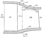
Фигура 1 - представленная в виде сбоку осевая вертикальная проекция ряда лопаток вентилятора, находящихся внутри корпуса, выполненного в соответствии с одним из примерных вариантов осуществления настоящего изобретения.Figure 1 is a side elevational axial view of a series of fan blades located inside a housing made in accordance with one exemplary embodiment of the present invention.
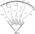
Фигура 2 - представленная в виде спереди радиальная проекция части вентилятора и корпуса, изображенной на фигуре 1, построенная по линии 2-2.Figure 2 is a frontal radial view of a part of the fan and the housing shown in figure 1, constructed along line 2-2.
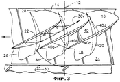
Фигура 3 - представленное в виде сверху сквозное изображение лопаток вентилятора, изображенных на фигуре 2, построенное по линии 3-3.Figure 3 is a top view of the through image of the fan blades shown in figure 2, built along the line 3-3.
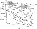
Фигура 4 - представленный в увеличенном масштабе осевой боковой вид трех расположенных по окружности одна за другой соседних лопаток вентилятора по их кромкам внутри круга, помеченного цифрой 4 на фигуре 1.Figure 4 is an enlarged axial side view of three adjacent fan blades arranged in a circle one after another along their edges inside a circle marked with the number 4 in figure 1.
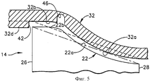
Фигура 5 - представленный в увеличенном масштабе осевой боковой вид кромки лопатки и сопряженного с ней корпуса, выполненных в соответствии с другим вариантом осуществления настоящего изобретения.Figure 5 is an enlarged axial lateral view of the edge of the blade and its associated body, made in accordance with another embodiment of the present invention.
Фигура 6 - представленная в виде сбоку осевая вертикальная проекция ряда лопаток компрессора, следующих за рядом лопаток статора, в соответствии с другим вариантом осуществления настоящего изобретения.6 is a side elevational axial view of a row of compressor vanes following a row of stator vanes in accordance with another embodiment of the present invention.
На фигуре 1 показана часть вентилятора 10 турбовентиляторного газотурбинного двигателя. Вентилятор 10 осесимметричен относительно осевой центральной линии оси 12.The figure 1 shows a portion of a fan 10 of a turbofan gas turbine engine. The fan 10 is axisymmetric about the axial center line of the
Вентилятор включает в себя ряд расположенных по окружности с промежутками друг относительно друга профилей 14 в виде примерных лопаток рабочего колеса вентилятора, показанного на фигурах 1-3. Как изначально показано на фигуре 3, каждый из профилей 14 включает в себя в общем вогнутую сторону нагнетания 16 и расположенную противоположно ей в окружном направлении в общем выпуклую сторону всасывания 18, проходящую в продольном или радиальном направлении с перекрытием по поперечным или радиальным сечениям от расположенного по радиусу внутри хвоста 20 до расположенной по радиусу снаружи кромки 22.The fan includes a number of
Как показано на фигуре 1, каждый профиль 14 проходит по радиусу наружу вдоль радиальной оси 24, относительно которой могут быть определены изменяющиеся радиальные или поперечные сечения профиля. Кроме того, каждый профиль имеет расположенные на расстоянии одна от другой в осевом направлении или по хорде переднюю и заднюю кромки 26, 28, между которыми в осевом направлении проходят стороны нагнетания и всасывания.As shown in FIG. 1, each
Как показано на фигуре 3, каждое радиальное или поперечное сечение профиля имеет обычную прямую хорду между передней и задней кромками, а также проходящую между ними выгнутую по дуге линию. Профиль скручен от хвоста к кромке для обеспечения взаимодействия с воздухом 30, проходящим поверх него во время работы. Хорды сечений варьируются по углу скручивания А от хвоста к кромке как обычно.As shown in figure 3, each radial or cross-section of the profile has the usual straight chord between the front and rear edges, as well as a line curved along them in an arc. The profile is twisted from tail to edge to allow interaction with
Путь прохождения потока воздуха, пропускаемого между профилями, ограничивается по радиусу снаружи кольцевым корпусом 32 вентилятора или компрессора, а по радиусу изнутри - выполненными за одно целое площадками 34 каждой лопатки, на которых располагаются хвосты 20. Обычный ласточкин хвост 36 надежно соединяет каждую лопатку с диском 38 рабочего колеса, имеющим ответные осевые пазы под ласточкин хвост для удерживания лопаток на нем в радиальном направлении.The path of the air flow passing between the profiles is limited radially from the outside by the
Как показано на фигуре 1, лопатки 14 вентилятора изображены внутри примерного кольцевого корпуса 32. Размер и конфигурация лопаток в типовом случае определяются таким образом, чтобы добиться получения желаемого максимального показателя пропускной способности по потоку при нагнетании для вентилятора, выраженной в единицах массы за секунду. Вентилятор изначально проектируется на получение максимального кпд сжатия при приемлемой величине запаса на потерю скорости (заглухание) или дросселирование.As shown in FIG. 1, the
Размер и конфигурация кромок лопаток в типовом случае подбираются таким образом, чтобы обеспечить по существу равномерный зазор, или щель, В между кромками и корпусом 32, что позволяет свести к минимуму утечки воздушного потока через этот зазор во время работы при предотвращении или уменьшении нежелательного задевания кромок за корпус. Обычный корпус (не показан) выполняется прямым в осевом направлении либо с цилиндрической внутренней поверхностью, обращенной к кромкам лопаток, либо с конической сходящейся или расходящейся поверхностью, обращенной к этим кромкам.The size and configuration of the edges of the blades are typically selected in such a way as to provide a substantially uniform gap, or slit, B between the edges and the
В связи с довольно значительным скручиванием лопаток типичным для первой ступени лопаток вентилятора, кромки лопаток частично проходят по окружности относительно внутренней поверхности корпуса и должны обязательно быть выгнуты в радиальном направлении наружу, чтобы обеспечить получение желаемого равномерного зазора между кромками и корпусом внутри цилиндрического или конического корпуса.Due to the rather significant twisting of the blades typical of the first stage of the fan blades, the edges of the blades partially extend around the circumference relative to the inner surface of the casing and must necessarily be bent radially outward to provide the desired uniform clearance between the edges and the casing inside a cylindrical or conical casing.
Конфигурация соседних лопаток в типовом случае разрабатывается в расчете на обеспечение прохода 40 для потока, имеющего сходящуюся-расходящуюся форму вблизи от кромок лопаток, как показано на фигуре 3, чтобы происходило замедление потока на участке между передней и задней кромками. Внутренняя форма прохода для потока вплоть до хвостов лопаток выполнена только расходящейся. Диффузия происходит в проходе для потока при повышении статического давления с уменьшением скорости. Вихрь при кромке действует в качестве блокировки, ограничивающей повышение статического давления.The configuration of adjacent blades is typically designed to provide a
Поскольку лопатки вентилятора, имеющие сравнительно большой размер, могут испытывать воздействие потока с высоким числом Маха на своих кромках, вихрь 30v при кромке, как показано схематично на фигурах 3 и 4, может вступать во взаимодействие с ударными волнами. Сверхзвуковой поток у кромок лопаток может создавать косые ударные волны, испускаемые передними кромками лопаток, и нормальные ударные волны, возникающие в проходе между соседними лопатками. Как указано выше, потери давления, вызываемые вихрями при кромках, способствуют дополнительному усилению этих воздействий ударной волны в зоне у кромок, что приводит к снижению пропускной способности при нагнетании и к ухудшению кпд при сжатии.Since the fan blades having a relatively large size can be affected by the flow with a high Mach number at their edges, the
В соответствии с настоящим изобретением, корпус 32 вентилятора, показанный на фигуре 1, имеет специально подобранный контур своей внутренней в радиальном направлении поверхности, определяющей собой неподвижный кожух, который по меньшей мере частично выполнен выпуклым в осевом направлении, располагаясь вокруг ряда лопаток 14 рабочего колеса, размещенного соосно внутри кожуха, причем кромки 22 лопаток дополняют собой контур корпуса, обеспечивая получение по существу равномерного зазора В между кромками и корпусом.In accordance with the present invention, the
Как показано в увеличенном масштабе на фигуре. 4, внутренняя поверхность корпуса 32, проходя в осевом направлении, охватывает собой лопатки 14 от передней до задней кромки 26, 28 и выполнена в осевом направлении выпуклой по меньшей мере в своей задней части 32а, охватывающей кромки при вершине лопаток у их задних кромок 28. Поскольку кромки 22 при вершине лопаток дополняют собой осевой контур корпуса, каждая такая кромка лопатки включает в себя заднюю часть 22а, которая выполнена вогнутой в радиальном направлении внутрь по меньшей мере в задней осевой части от задней кромки 28 по направлению к передней кромке 26. Таким образом, обращенные друг к другу в радиальном направлении задние части кромок 22 лопаток и внутренняя поверхность корпуса дополняют друг друга, причем первые выполнены вогнутыми в радиальном направлении внутрь, а последняя выполнена по радиусу выпуклой внутрь в осевом направлении с тем, чтобы обеспечивался равномерный зазор В между ними.As shown on an enlarged scale in the figure. 4, the inner surface of the
Осевой контур внутренней поверхности корпуса, показанный на фигуре 4, представляет собой только лишь одну составляющую сложной трехмерной (3-D) конфигурации соответствующих проходов 40 для потока между соседними друг с другом в окружном направлении лопатками 14. Радиальные конфигурации лопаток в поперечном сечении от передней к задней кромке обычно определяются из условия обеспечения максимальной пропускной способности по потоку при нагнетании и наивысшего значения кпд при сжатии с приемлемой величиной запаса на самопроизвольный останов. Каждый проход 40 для потока включает в себя обычную впускную зону 40а, как показано на фигурах 3 и 4. Эта впускная зона проходит от стороны нагнетания у передней кромки одной лопатки до стороны всасывания позади передней кромки следующей далее соседней лопатки и представляет собой зону, которая охватывает собой первую закрытую волну сжатия разрежения во время работы.The axial contour of the inner surface of the casing, shown in figure 4, represents only one component of a complex three-dimensional (3-D) configuration of the
Непосредственно позади впускной зоны 40а находится горловина 40b прохода, которая проходит от стороны нагнетания у передней кромки, одной лопатки по существу перпендикулярно по отношению к соответствующей части на стороне всасывания следующей далее соседней лопатки позади относительно передней кромки и впускной зоны. Проход для воздуха выполнен сходящимся от его горловины к сужению 40с, имеющему минимальное проходное сечение и соответственно расположенному по существу сзади области середины хорды лопаток, начиная от которой проход для потока выполнен расходящимся в направлении к выпускной части 40d, имеющей большее проходное сечение, причем это сужение ограничивается участком между стороной всасывания у задней кромки одной лопатки по существу перпендикулярно по отношению к стороне нагнетания следующей далее соседней лопатки впереди ее задней кромки.Directly behind the
Благодаря сходящемуся-расходящемуся контуру каждого прохода 40 для потока обеспечивается замедление движения воздушного потока, что, в свою очередь, способствует повышению давления воздуха, поскольку происходит диффузия, в осевом направлении по мере того, как воздух перемещается между лопатками вентилятора.Due to the converging-diverging contour of each
Важное значение такого предпочтительного контура, предложенного для корпуса 32, может быть дополнительно оценено при рассмотрении фигуры 5, на которой контуры корпуса и дополняющей его лопатки вентилятора представлены в еще более увеличенном масштабе. Пунктирной линией, проведенной внутри корпуса 32, показана обычная для него коническая конфигурация, которая сочетается в работе с прямолинейной конической кромкой при вершине лопатки, показанной штрихпунктирной линией в виде осевого профиля, характерного для обычной лопатки вентилятора. Путем выполнения задней части 32а внутренней поверхности корпуса таким образом, чтобы она имела в осевом направлении выпуклую форму впереди, если смотреть в направлении потока, задних кромок лопаток, может быть получено местное уменьшение диффузии в вихре, создаваемом во время работы у кромки при вершине лопатки.The importance of such a preferred circuit proposed for the
Уменьшение диффузии в вихре у кромки соответственно способствует уменьшению обусловленных этим явлением потерь давления и сопутствующего ослабления аэродинамической блокировки потока, в результате чего возрастают как пропускная способность по потоку при нагнетании, так и кпд сжатия в пределах соответствующих ограничений, связанных с конкретными размерными характеристиками вентилятора. Наружные диаметры лопаток вентилятора по их передней и задней кромкам, а также соответствующие им внутренние диаметры противолежащих указанным кромкам частей корпуса могут оставаться точно такими же, по своей величине, как и в обычных конструкциях, но при этом обеспечивается осуществляемое с целью улучшения соответствующее изменение контура внутренней поверхности в осевом направлении между указанными кромками с тем, чтобы добиться местного улучшения аэродинамической характеристики.The decrease in diffusion in the vortex at the edge, respectively, helps to reduce the pressure losses caused by this phenomenon and the associated weakening of the aerodynamic blocking of the flow, as a result of which both the flow throughput upon injection and the compression efficiency increase, within the corresponding limitations associated with the specific dimensional characteristics of the fan. The outer diameters of the fan blades along their leading and trailing edges, as well as the corresponding inner diameters of the housing parts opposite to the indicated edges, can remain exactly the same in size as in conventional designs, but at the same time a corresponding change in the contour of the inner surfaces in the axial direction between these edges in order to achieve local improvement in aerodynamic performance.
Выпуклая задняя часть 32а внутренней поверхности корпуса может быть выполнена самым разнообразным путем, в том числе непрерывно изогнутой, либо составленной из отдельных конических участков, в зависимости от того, что будет желательно. Далее, за указанной задней частью корпус может иметь соответствующий контур, обеспечивающий обратный переход к заданному внутреннему диаметру, но уже с наружной стороны относительно кромок лопаток.The convex
Более конкретно, как показано на фигурах 4 и 5, внутренняя поверхность корпуса включает в себя, кроме того, также переднюю часть 32b, расположенную в осевом направлении впереди, если смотреть в направлении потока, относительно задней части 32а и охватывающую кромку при вершине лопаток у передних их кромок. Передняя часть 32b корпуса имеет больший диаметр по оси, проходящей через центральную линию, чем его задняя часть 32а, и, таким образом, корпус выполнен сходящимся на участке между этими двумя частями.More specifically, as shown in figures 4 and 5, the inner surface of the casing also includes a
Например, внутренняя поверхность корпуса предпочтительно включает также в свой состав и промежуточную часть 32с, расположенную в осевом направлении на участке между передней и задней ее частями, соответственно 32b и 32а, которая выполнена сходящейся на указанном участке в заднем направлении.For example, the inner surface of the housing preferably also includes an
Дополняющие рассматриваемый контур кромки 22 при вершине лопаток включают в себя переднюю в осевом направлении часть 22b, а также промежуточную, или расположенную в середине хорды, часть 22с, которые проходят параллельно соответствующим частям корпуса. Соответствующие части кромки при вершине лопаток имеют контур, точно повторяющий контур соответствующих им частей внутренней поверхности, корпуса, охватывающей лопатки, на участке между передней и задней кромками лопаток, благодаря чему выдерживается по существу равномерный радиальный зазор В между этими кромками и внутренней поверхностью корпуса. Поскольку промежуточная часть 32с корпуса выполнена сходящейся в направлении потока, то и промежуточная часть 22с кромки при вершине лопаток также выполнена сходящейся или же наклонной внутрь по профилю в осевом направлении на участке между передней и задней ее частями.Complementing the contour of the
Внутренняя поверхность корпуса 32 предпочтительно выполняется таким образом, чтобы контур ее обеспечивал получение улучшенного распределения статического давления в осевом направлении, благодаря чему происходит местное уменьшение диффузии в вихре, создаваемом у кромки, при вершине лопаток, а также улучшается аэродинамическая характеристика. Дополнительно к этому, местное уменьшение диффузии способствует также ослаблению нормальной ударной волны для сверхзвуковых применений, что, в свою очередь, позволяет добиться уменьшения степени диффузии в вихре поперечно этой ударной волне. Поскольку вихрь, создаваемый у кромки при вершине лопаток, подвергается воздействию менее резкого градиента возрастающего статического давления позади ударной волны, то при этом возникает тенденция к еще большему сокращению потерь давления, а также к уменьшению или предотвращению миграции вихря в направлении к стороне нагнетания соседней лопатки.The inner surface of the
Уменьшение силы нормальной ударной волны, а также меньшие потери давления в вихре и ослабление блокировки потока, происходящей вследствие образования вихря - все это способствует повышению кпд рабочего колеса компрессора с увеличением пропускной способности при нагнетании и расширением диапазона дросселирования. В одной из конструкций, исследованной с применением метода трехмерного анализа вязкого потока на околозвуковом режиме вращения рабочего колеса при высокой удельной величине потока, корпус с контуром, выполненным в соответствии с приведенным для примера вариантом осуществления настоящего изобретения, показал результаты, свидетельствующие о существенном увеличении общего воздушного потока и о соответствующем более высоком значении кпд рабочего колеса при той же самой скорости вращения, что и при применении сопоставимого конического корпуса обычной конструкции.A decrease in the force of a normal shock wave, as well as smaller losses of pressure in the vortex and a weakening of the flow blocking due to the formation of the vortex, all this contributes to an increase in the efficiency of the compressor impeller with an increase in throughput during injection and widening of the throttling range. In one of the structures investigated using the method of three-dimensional analysis of viscous flow in a transonic mode of impeller rotation at a high specific flow rate, a casing with a circuit made in accordance with an example embodiment of the present invention showed results indicating a significant increase in the total air flow and the corresponding higher value of the efficiency of the impeller at the same speed of rotation as when applying a comparable conical orpusa conventional design.
В приведенном для примера варианте осуществления настоящего изобретения, показанном на фигуре 4, передняя часть 32b корпуса, располагающаяся поверх передних кромок лопастей, имеет больший наружный диаметр при замере его по оси, проходящей через центральную линию вентилятора, чем задняя часть 32а корпуса, располагающаяся поверх задних кромок лопаток. Контур внутренней поверхности корпуса предпочтительно подбирается из условия обеспечения местного раскрывания впускной зоны и сужения проходов для потока, тогда как выходная или выпускная зона проходов для потока остается такой же для данного применения. Это также способствует уменьшению эффективного изгиба при высоких скоростях вращения вентилятора, обеспечивая увеличение общего воздушного потока при соответствующем повышении кпд сжатия.In the exemplary embodiment of the present invention shown in FIG. 4, the
Поскольку наружные диаметры по передним кромкам лопаток и по их задним кромкам предпочтительно подбираются каждый раз отдельно для каждой конкретной конструкции вентилятора, а также с учетом применения более совершенного контура передней и задней частей корпуса, соответственно 32b и 32а, предпочтительно было бы также, чтобы промежуточная часть 32с корпуса была выполнена с более резким переходом при ее схождении, чем его передняя и задняя части, соответственно 32b и 32а, что обеспечило бы получение аэродинамического перехода между различными местными воздействиями, возникающими в зонах расположения передних и задних кромок лопаток.Since the outer diameters along the leading edges of the blades and along their trailing edges are preferably selected each time separately for each particular fan design, and also taking into account the use of a more perfect contour of the front and rear parts of the housing, respectively 32b and 32a, it would also be preferable that the
Как указано выше, задняя часть 32а корпуса, располагающаяся поверх задних кромок лопаток, в предпочтительном варианте осуществления настоящего изобретения выполнена дугообразно выпуклой в осевом направлении. В альтернативных вариантах осуществления настоящего изобретения выпуклый контур задней части корпуса может складываться из последовательно расположенных в осевом направлении прямых участков, к примеру, таких, какими могут являться один или более конических участков, располагающихся поверх зоны размещения задних кромок лопаток.As indicated above, the
Промежуточная часть 32с корпуса предпочтительно выполняется прямой в осевом направлении в виде конического участка, имеющего угол наклона С, или половинный угол конусности, который существенно больше, чем соответствующие углы наклона его передней и задней частей, соответственно 32b и 32а. Таким образом, передняя и задняя части имеют ограниченный наклон, или сходимость, причем основная доля общего наклона и сходимости приходится на промежуточную часть 32с корпуса, соответствующую участку от середины хорды до задней части по кромке при вершине лопаток, вокруг которых располагается указанная промежуточная часть.The
Передняя часть 32b корпуса предпочтительно выполняется прямой в осевом направлении там, где она начинается поверх передних кромок лопаток, либо имея по существу постоянный радиус или внутренний диаметр, либо имея незначительное схождение и образуя собой конический участок. Кроме того, передняя часть корпуса 32b предпочтительно выполняется с переходом к дугообразной в осевом направлении форме в месте соединения ее с промежуточной частью 32с корпуса. Таким образом, передняя часть 32b корпуса выполняется прямой в осевом направлении в пределах переднего своего участка, располагающегося поверх передних кромок лопаток, и предпочтительно является выпуклой в пределах заднего своего участка в месте соединения ее с предпочтительно выполняемой прямой конической промежуточной частью 32с. Далее следует задняя часть 32а корпуса, которая, в свою очередь, имеет выпуклый в осевом направлении контур, завершая собой комбинированный контур, который имеет в осевом направлении весь корпус в целом, охватывающий собой кромки при вершине лопаток на всем протяжении этих кромок, начиная от передней и кончая задней кромками лопаток.The
Как указано выше, осевой контур кромок 22 при вершине лопаток, поскольку они вытянуты по радиусу наружу по направлению к внутренней поверхности корпуса 32, дополняет собой контур соответствующих ее частей. Соответственно, передние части 22b кромок при вершине лопаток выполнены с переходом в виде сбоку в осевом направлении от прямых по своей форме к выпуклым в осевом направлении с тем, чтобы прилегать к дополняемому ими осевому контуру передней части 32b корпуса, которая выполнена с переходом от прямой к выпуклой в осевом направлении. Промежуточные части 22с кромок при вершине лопаток выполнены коническими в осевом направлении с тем, чтобы дополнять собой коническую в осевом направлении промежуточную часть 32с корпуса. И наконец, задние части 22а кромок при вершине лопаток выполнены вогнутыми в осевом направлении с тем, чтобы дополнять собой выпуклые в осевом направлении задние части 32а корпуса.As indicated above, the axial contour of the
Таким образом, осевой контур внутренней поверхности корпуса 32 там, где он охватывает собой кромки при вершине лопаток на всем протяжении этих кромок от передней до задней кромок лопаток, варьируется с целью обеспечения благоприятного распределения статического давления в осевом направлении с тем, чтобы уменьшить диффузию в вихрях, создаваемых у кромок при вершине лопаток, а также ослабить нормальную ударную волну во время работы на сверхзвуковом режиме, в дополнение к тем преимуществам, которые рассмотрены были ранее в приведенном здесь выше описании.Thus, the axial contour of the inner surface of the
Как показано на фигуре 1, внутренняя поверхность корпуса 32 дополнительно включает в себя кольцевую впускную часть 32d, находящуюся впереди, если смотреть в направлении потока, относительно передней части 32b с внешней стороны по отношению к передним кромкам 26 лопаток. Впускная часть 32d может быть выполнена цилиндрической, конически расходящейся или же конически сходящейся и располагается соосно другим частям корпуса, обеспечивая поступление к ним воздушного потока 30. На фигуре 4 впускная часть 32d показана в предпочтительном расходящемся в осевом направлении исполнении с плавным сопряжением ее с передней частью 32b кожуха, что позволяет получить максимальное проходное сечение во впускной зоне 40а.As shown in FIG. 1, the inner surface of the
В варианте осуществления настоящего изобретения, показанном на фигуре 5, впускная часть 32b имеет уменьшенный внутренний диаметр и соединяется с передней частью 32b корпуса, располагаясь соосно с ней, а в месте соединения этих двух частей друг с другом имеется выступающий в радиальном направлении наружу уступ 42, благодаря наличию которого внутренняя поверхность корпуса, охватывающая собой кромки при вершине лопаток, располагается в кольцевом углублении, ограничивающем кожух, заключающий в себе кромки при вершине лопаток. Кольцевое углубление, определяющее собой кожух, имеет обычную форму, но в предпочтительном исполнении оно может иметь внутреннюю поверхность с осевым контуром, который выполняется в соответствии с настоящим изобретением, что позволяет улучшить рабочую характеристику вентилятора.In the embodiment of the present invention, shown in figure 5, the
Представленный на фигурах 1-5 вариант осуществления настоящего изобретения характерен для сравнительно длинной лопатки вентилятора, внешняя часть которой обеспечивает повышение давления воздуха, выходящего из турбовентиляторного двигателя и создающего движущую силу. Однако настоящее изобретение может быть использовано также и в других типах профилей лопаток компрессора, к примеру, таком, какой представлен в схематическом виде на фигуре 6 в форме лопатки 14B осевого компрессора.Presented in figures 1-5, an embodiment of the present invention is characteristic of a relatively long fan blade, the outer part of which provides an increase in pressure of the air leaving the turbofan engine and creating a driving force. However, the present invention can also be used in other types of compressor blade profiles, for example, such as shown schematically in FIG. 6 in the form of an
Лопатка 14В этого компрессора простирается в радиальном направлении наружу относительно опорного диска или барабана, 38а, причем имеется одно или несколько рабочих колес осевого типа и соответствующих им ступеней статора, располагаемых в компрессоре обычным порядком. Впереди ряда лопаток компрессора, если смотреть в направлении потока, располагается соответствующий ряд лопаток 44 статора, которые направляют воздушный поток 30 к лопаткам компрессора.The
Воздушный поток направляется в осевом направлении от лопатки к лопатке через несколько ступеней при ограничении потока в радиальном направлении с внешней и с внутренней стороны соответствующими сдерживающими стенками, определяющими собой путь движения потока. Корпус представляет собой внешнюю такую стенку, а барабан внутреннюю стенку, между которыми находятся имеющие соответствующий профиль лопатки ступеней статора и компрессора. Лопатки статора отстоят от внутренней стенки с обеспечением соответствующего радиального зазора между лопатками и этой стенкой, аналогичного по своему назначению радиальному зазору у кромок при вершине лопаток компрессора, а именно - чтобы обеспечить возможность относительного вращательного движения.The air flow is directed in the axial direction from the blade to the blade through several stages while restricting the flow in the radial direction from the outside and from the inside with the corresponding restraining walls, which determine the flow path. The housing is such an external wall, and the drum is an internal wall, between which are located the blades of the stator and compressor stages having the corresponding profile. The stator vanes are separated from the inner wall with the corresponding radial clearance between the vanes and this wall, which is similar in purpose to the radial clearance at the edges at the top of the compressor vanes, namely, to allow relative rotational movement.
В этом варианте осуществления настоящего изобретения внутренняя поверхность корпуса включает в себя примыкающие одна к другой заднюю и переднюю свои части, соответственно 32а и 32b, охватывающие собой лопатки 14B компрессора. Вся внутренняя поверхность корпуса в целом выполнена выпуклой в осевом направлении в рассматриваемом варианте исполнения настоящего изобретения, и сделано это опять же с целью обеспечить местное уменьшение диффузии в вихрях, создаваемых у кромок при вершине лопаток, и увеличить тем самым пропускную способность по воздушному потоку при нагнетании за счет ослабления эффекта блокирования потока и уменьшения потерь давления.In this embodiment of the present invention, the inner surface of the housing includes adjacent to one another back and front parts, respectively 32a and 32b, covering the
В этом же варианте осуществления настоящего изобретения кольцевая впускная часть 32d корпуса соединяется при обеспечении соосности между ними с передней частью 32b, расположенной впереди относительно нее, если смотреть в направлении потока, и предпочтительно выполняется сходящейся в направлении потока, имея при этом либо коническое сечение, либо выпуклое в осевом направлении сечение, как показано на примере предпочтительного варианта осуществления настоящего изобретения.In the same embodiment of the present invention, the
Кромки при вершине лопаток 14 В компрессора имеют очертание, дополняющее собой и сочетающееся с выпуклым осевым контуром внутренней поверхности корпуса с тем, чтобы обеспечить наличие по существу равномерного радиального зазора между лопатками и этой поверхностью. Соответственно, примыкающие одна к другой передняя и задняя части 22а и 22b кромок при вершине лопаток выполняются вогнутыми в осевом направлении с тем, чтобы дополнять собой и сочетаться с осевым выпуклым контуром охватывающей их внутренней поверхности корпуса.The edges at the apex of the compressor blades 14 V have a shape complementary to and combined with the convex axial contour of the inner surface of the casing so as to ensure a substantially uniform radial clearance between the blades and this surface. Accordingly, the leading front and
Рабочая характеристика компрессора может быть улучшена дополнительно посредством выполнения в корпусе расположенных по окружности пазов или канавок. В встречающихся на практике рядовых условиях такие канавки могут обеспечивать увеличение запаса на дросселирование рабочего колеса, но это обычно приводит к сопутствующему снижению кпд рабочего колеса.The performance of the compressor can be further improved by making circumferential grooves or grooves in the housing. Under ordinary conditions encountered in practice, such grooves can provide an increase in the throttle margin, but this usually leads to a concomitant decrease in the efficiency of the impeller.
Однако такие канавки в сочетании с выпуклым контуром корпуса, рассмотренным в приведенном здесь выше описании, позволяют получить дополнительное преимущество, которое в противном случае получить было бы невозможно. Например, на фигуре 4 дополнительно показана расположенная по окружности одиночная канавка 46, выполненная в передней части 32 корпуса, которая обращена своей открытой стороной к кромкам 22 при вершине лопаток, расположенным с внутренней стороны относительно этой канавки вне ее. Такая канавка, выполненная в корпусе, и выпуклый контур его, дополняя собой друг друга, обеспечивают максимальное улучшение рабочей характеристики и устойчивости режима работы.However, such grooves in combination with the convex body contour discussed in the description above provide an additional advantage that would otherwise be impossible. For example, figure 4 additionally shows a circumferential
Имеющаяся в корпусе канавка оказывает такое воздействие на рабочий процесс, которое улучшает его стабильность, а также позволяет применить более крутой выпуклый контур при проектировании, который в противном случае применить было бы невозможно. Нарушение непрерывности, возникающее при наличии канавки 46, позволяет добиться получения максимального проходного сечения во впускной зоне и в зоне сужения и одновременно увеличить также кривизну выпуклой части 32а корпуса, расположенной за указанными зонами по направлению потока. При отсутствии такой канавки путь прохождения потока через корпус мог бы иметь в противном случае на ее месте более вогнутую кривизну, что могло бы привести к ухудшению рабочей характеристики и устойчивости режима работы.The groove in the housing has an effect on the working process that improves its stability, and also makes it possible to use a steeper convex contour during design, which otherwise would be impossible to apply. The disruption of continuity that occurs when there is a
Соответствующего ухудшения рабочей характеристики, обычно связываемого с наличием в корпусе канавок, удается избежать путем применения меньшего количества канавок, а предпочтительно - всего одной единственной канавки, а также за счет обеспечения более благоприятного распределения статического давления у кромок при вершине лопаток при применении предложенного контура корпуса.The corresponding deterioration in performance, usually associated with the presence of grooves in the housing, can be avoided by using fewer grooves, and preferably only one single groove, and also by providing a more favorable distribution of static pressure at the edges at the top of the blades when applying the proposed housing contour.
В вариантах осуществления настоящего изобретения, рассмотренных в приведенном здесь выше описании, может быть получено увеличение пропускной способности при нагнетании и повышение кпд Поскольку в варианте осуществления настоящего изобретения, представленном на фигуре 6, имеется только лишь выпуклая в осевом направлении внутренняя поверхность корпуса, этот вариант не позволяет реализовать все преимущества, рассмотренные в приведенном здесь выше описании применительно к первому варианту осуществления настоящего изобретения.In the embodiments of the present invention described in the above description, an increase in discharge throughput and an increase in efficiency can be obtained. Since in the embodiment of the present invention shown in FIG. 6, there is only an axially convex inner surface of the housing, this embodiment is not allows you to realize all the advantages discussed in the above description with respect to the first embodiment of the present invention.
Однако различные варианты осуществления настоящего изобретения, рассмотренные, в приведенном здесь выше описании, позволяют при минимальных изменениях в геометрии корпуса и кромки при вершине лопаток добиться заметного улучшения рабочих характеристик лопаток компрессора и вентилятора без каких-либо иных изменений габаритного размера ступеней вентилятора или компрессора. При заданных технических условиях на проектирование применение имеющих рассмотренный выше контур корпусов и согласованно дополняющих этот контур кромок при вершине лопаток позволяет обеспечить существенное улучшение рабочей характеристики, которое в противном случае невозможно было бы получить. Эти новые признаки могут быть использованы и для внедрения их в существующие конструкции в тех случаях, в которых это практически осуществимо, обеспечив тем самым соответствующее улучшение рабочей характеристики вентиляторов и компрессоров, работающих либо в дозвуковом или сверхзвуковом режиме.However, the various embodiments of the present invention discussed in the above description allow, with minimal changes in the geometry of the body and the edge at the top of the blades, to achieve a noticeable improvement in the performance of the compressor and fan blades without any other changes in the overall size of the fan or compressor stages. Given the technical specifications for the design, the use of the hulls considered above and matching the edges at the top of the blades in a consistent manner allows for a significant improvement in performance that would otherwise not have been possible. These new features can also be used to introduce them into existing structures in those cases in which it is practically feasible, thereby ensuring a corresponding improvement in the operating characteristics of fans and compressors operating either in subsonic or supersonic modes.
В приведенном здесь выше описании рассмотрены были те варианты осуществления настоящего изобретения, которые считаются предпочтительными и примерными, но специалистам в данной области техники должно быть вполне очевидно, что на основании изложенных здесь принципов изобретения могут быть разработаны также и другие модификации данного изобретения, и поэтому желательно определить различные такие модификации, которые не выходят за действительные пределы существа и объема изобретения, в прилагаемой формуле изобретения.In the above description, those embodiments of the present invention were considered that are considered preferred and exemplary, but it should be obvious to those skilled in the art that other modifications of the invention may also be developed based on the principles of the invention set forth herein, and therefore it is desirable identify various such modifications that do not go beyond the valid limits of the essence and scope of the invention in the attached claims.
Claims (23)
Applications Claiming Priority (2)
| Application Number | Priority Date | Filing Date | Title |
|---|---|---|---|
| US09/507,409 | 2000-02-18 | ||
| US09/507,409 US6338609B1 (en) | 2000-02-18 | 2000-02-18 | Convex compressor casing |
Publications (2)
| Publication Number | Publication Date |
|---|---|
| RU2001104476A RU2001104476A (en) | 2003-01-20 |
| RU2247867C2 true RU2247867C2 (en) | 2005-03-10 |
Family
ID=24018535
Family Applications (1)
| Application Number | Title | Priority Date | Filing Date |
|---|---|---|---|
| RU2001104476/06A RU2247867C2 (en) | 2000-02-18 | 2001-02-16 | Compressor housing (versions) and compressor impeller blade |
Country Status (7)
| Country | Link |
|---|---|
| US (1) | US6338609B1 (en) |
| EP (1) | EP1126133A3 (en) |
| JP (1) | JP5235253B2 (en) |
| BR (1) | BR0100566B1 (en) |
| CA (1) | CA2333809C (en) |
| PL (1) | PL200472B1 (en) |
| RU (1) | RU2247867C2 (en) |
Cited By (3)
| Publication number | Priority date | Publication date | Assignee | Title |
|---|---|---|---|---|
| RU2459122C2 (en) * | 2006-11-08 | 2012-08-20 | Снекма | Gas turbine engine inlet blade; gas turbine engine fan and gas turbine engine |
| RU2626886C2 (en) * | 2012-01-30 | 2017-08-02 | Снекма | Lash of the turbojet motor fan, turbojet engine fan and turbojet engine |
| RU2655085C2 (en) * | 2012-07-27 | 2018-05-23 | Снекма | Part of changing the contour of aerodynamic path |
Families Citing this family (74)
| Publication number | Priority date | Publication date | Assignee | Title |
|---|---|---|---|---|
| US6508630B2 (en) | 2001-03-30 | 2003-01-21 | General Electric Company | Twisted stator vane |
| JP3927886B2 (en) * | 2002-08-09 | 2007-06-13 | 本田技研工業株式会社 | Axial flow compressor |
| WO2004015276A1 (en) * | 2002-08-13 | 2004-02-19 | Honeywell International, Inc. | Compressor |
| FR2851798B1 (en) * | 2003-02-27 | 2005-04-29 | Snecma Moteurs | TURBOREACTOR TURBINE BOW |
| DE10352253A1 (en) * | 2003-11-08 | 2005-06-09 | Alstom Technology Ltd | Compressor blade |
| US7690890B2 (en) * | 2004-09-24 | 2010-04-06 | Ishikawajima-Harima Heavy Industries Co. Ltd. | Wall configuration of axial-flow machine, and gas turbine engine |
| US7217096B2 (en) * | 2004-12-13 | 2007-05-15 | General Electric Company | Fillet energized turbine stage |
| US7195456B2 (en) * | 2004-12-21 | 2007-03-27 | United Technologies Corporation | Turbine engine guide vane and arrays thereof |
| US7134842B2 (en) * | 2004-12-24 | 2006-11-14 | General Electric Company | Scalloped surface turbine stage |
| US7249933B2 (en) * | 2005-01-10 | 2007-07-31 | General Electric Company | Funnel fillet turbine stage |
| US20060198726A1 (en) * | 2005-03-07 | 2006-09-07 | General Electric Company | Apparatus for eliminating compressor stator vibration induced by tip leakage vortex bursting |
| GB0506685D0 (en) * | 2005-04-01 | 2005-05-11 | Hopkins David R | A design to increase and smoothly improve the throughput of fluid (air or gas) through the inlet fan (or fans) of an aero-engine system |
| US7476086B2 (en) * | 2005-04-07 | 2009-01-13 | General Electric Company | Tip cambered swept blade |
| US7374403B2 (en) * | 2005-04-07 | 2008-05-20 | General Electric Company | Low solidity turbofan |
| US7220100B2 (en) * | 2005-04-14 | 2007-05-22 | General Electric Company | Crescentic ramp turbine stage |
| US20060237168A1 (en) * | 2005-04-21 | 2006-10-26 | Belady Christian L | Air mover with thermally coupled guide vanes |
| US7811053B2 (en) * | 2005-07-22 | 2010-10-12 | United Technologies Corporation | Fan rotor design for coincidence avoidance |
| GB0620769D0 (en) * | 2006-10-19 | 2006-11-29 | Rolls Royce Plc | A fan blade |
| US7938168B2 (en) * | 2006-12-06 | 2011-05-10 | General Electric Company | Ceramic cores, methods of manufacture thereof and articles manufactured from the same |
| US7624787B2 (en) * | 2006-12-06 | 2009-12-01 | General Electric Company | Disposable insert, and use thereof in a method for manufacturing an airfoil |
| US20080135721A1 (en) * | 2006-12-06 | 2008-06-12 | General Electric Company | Casting compositions for manufacturing metal casting and methods of manufacturing thereof |
| US8413709B2 (en) * | 2006-12-06 | 2013-04-09 | General Electric Company | Composite core die, methods of manufacture thereof and articles manufactured therefrom |
| US7487819B2 (en) * | 2006-12-11 | 2009-02-10 | General Electric Company | Disposable thin wall core die, methods of manufacture thereof and articles manufactured therefrom |
| US8884182B2 (en) | 2006-12-11 | 2014-11-11 | General Electric Company | Method of modifying the end wall contour in a turbine using laser consolidation and the turbines derived therefrom |
| GB0712561D0 (en) * | 2007-06-28 | 2007-08-08 | Rolls Royce Plc | A blade mounting |
| EP2146053A1 (en) * | 2008-07-17 | 2010-01-20 | Siemens Aktiengesellschaft | Axial turbomachine with low tip leakage losses |
| EP2146054A1 (en) * | 2008-07-17 | 2010-01-20 | Siemens Aktiengesellschaft | Axial turbine for a gas turbine |
| US8061980B2 (en) * | 2008-08-18 | 2011-11-22 | United Technologies Corporation | Separation-resistant inlet duct for mid-turbine frames |
| FR2940374B1 (en) * | 2008-12-23 | 2015-02-20 | Snecma | COMPRESSOR HOUSING WITH OPTIMIZED CAVITIES. |
| US8662834B2 (en) | 2009-06-30 | 2014-03-04 | General Electric Company | Method for reducing tip rub loading |
| US8657570B2 (en) | 2009-06-30 | 2014-02-25 | General Electric Company | Rotor blade with reduced rub loading |
| CA2766534C (en) * | 2009-06-30 | 2017-12-12 | General Electric Company | Rotor blade and method for reducing tip rub loading |
| US8393872B2 (en) * | 2009-10-23 | 2013-03-12 | General Electric Company | Turbine airfoil |
| GB201006449D0 (en) * | 2010-04-19 | 2010-06-02 | Rolls Royce Plc | Blades |
| US8668459B2 (en) * | 2010-05-28 | 2014-03-11 | Hamilton Sundstrand Corporation | Turbine blade walking prevention |
| FR2961564B1 (en) | 2010-06-17 | 2016-03-04 | Snecma | COMPRESSOR AND OPTIMIZED TURBOMACHINE |
| GB2483059A (en) * | 2010-08-23 | 2012-02-29 | Rolls Royce Plc | An aerofoil blade with a set-back portion |
| US8668446B2 (en) | 2010-08-31 | 2014-03-11 | General Electric Company | Supersonic compressor rotor and method of assembling same |
| US9022730B2 (en) | 2010-10-08 | 2015-05-05 | General Electric Company | Supersonic compressor startup support system |
| JP5502695B2 (en) * | 2010-10-14 | 2014-05-28 | 株式会社日立製作所 | Axial flow compressor |
| US8864454B2 (en) | 2010-10-28 | 2014-10-21 | General Electric Company | System and method of assembling a supersonic compressor system including a supersonic compressor rotor and a compressor assembly |
| US8657571B2 (en) | 2010-12-21 | 2014-02-25 | General Electric Company | Supersonic compressor rotor and methods for assembling same |
| US8827640B2 (en) | 2011-03-01 | 2014-09-09 | General Electric Company | System and methods of assembling a supersonic compressor rotor including a radial flow channel |
| US8777793B2 (en) | 2011-04-27 | 2014-07-15 | United Technologies Corporation | Fan drive planetary gear system integrated carrier and torque frame |
| US8770929B2 (en) | 2011-05-27 | 2014-07-08 | General Electric Company | Supersonic compressor rotor and method of compressing a fluid |
| US8550770B2 (en) | 2011-05-27 | 2013-10-08 | General Electric Company | Supersonic compressor startup support system |
| EP2530330B1 (en) * | 2011-06-01 | 2016-05-25 | MTU Aero Engines AG | Rotor blade for the compressor of a turbo engine, compressor and turbo machine |
| US9102397B2 (en) * | 2011-12-20 | 2015-08-11 | General Electric Company | Airfoils including tip profile for noise reduction and method for fabricating same |
| US20130192198A1 (en) | 2012-01-31 | 2013-08-01 | Lisa I. Brilliant | Compressor flowpath |
| US10400629B2 (en) | 2012-01-31 | 2019-09-03 | United Technologies Corporation | Gas turbine engine shaft bearing configuration |
| US9038366B2 (en) | 2012-01-31 | 2015-05-26 | United Technologies Corporation | LPC flowpath shape with gas turbine engine shaft bearing configuration |
| US8863491B2 (en) | 2012-01-31 | 2014-10-21 | United Technologies Corporation | Gas turbine engine shaft bearing configuration |
| US9085983B2 (en) | 2012-03-29 | 2015-07-21 | General Electric Company | Apparatus and method for purging a gas turbine rotor |
| BR112014026360A2 (en) | 2012-04-23 | 2017-06-27 | Gen Electric | turbine airfoil and turbine blade |
| US9121285B2 (en) * | 2012-05-24 | 2015-09-01 | General Electric Company | Turbine and method for reducing shock losses in a turbine |
| CN103062113A (en) * | 2013-01-23 | 2013-04-24 | 薛文义 | Fan mechanism of turbo-fan engine |
| US9568009B2 (en) | 2013-03-11 | 2017-02-14 | Rolls-Royce Corporation | Gas turbine engine flow path geometry |
| US9879540B2 (en) | 2013-03-12 | 2018-01-30 | Pratt & Whitney Canada Corp. | Compressor stator with contoured endwall |
| JP6012519B2 (en) * | 2013-03-21 | 2016-10-25 | 三菱重工業株式会社 | Turbine and rotating machine equipped with the same |
| US9245851B2 (en) * | 2013-07-18 | 2016-01-26 | Fuji Electric Co., Ltd. | Semiconductor device and method of manufacturing semiconductor device |
| FR3021706B1 (en) * | 2014-05-28 | 2020-05-15 | Safran Aircraft Engines | AIRCRAFT TURBOPROPELLER COMPRISING TWO COAXIAL PROPELLERS. |
| US9470093B2 (en) | 2015-03-18 | 2016-10-18 | United Technologies Corporation | Turbofan arrangement with blade channel variations |
| BR112017020559B1 (en) * | 2015-04-15 | 2022-11-16 | Robert Bosch Gmbh | FREE END AXIAL FAN SET |
| JP6421091B2 (en) * | 2015-07-30 | 2018-11-07 | 三菱日立パワーシステムズ株式会社 | Axial flow compressor, gas turbine including the same, and stationary blade of axial flow compressor |
| US10808539B2 (en) | 2016-07-25 | 2020-10-20 | Raytheon Technologies Corporation | Rotor blade for a gas turbine engine |
| US10458426B2 (en) | 2016-09-15 | 2019-10-29 | General Electric Company | Aircraft fan with low part-span solidity |
| JP6770594B2 (en) * | 2017-02-08 | 2020-10-14 | 三菱重工エンジン&ターボチャージャ株式会社 | Centrifugal compressor and turbocharger |
| USD911512S1 (en) | 2018-01-31 | 2021-02-23 | Carrier Corporation | Axial flow fan |
| EP3969761A1 (en) | 2019-05-14 | 2022-03-23 | Carrier Corporation | Centrifugal compressor including diffuser pressure equalization feature |
| IT201900007935A1 (en) * | 2019-06-04 | 2020-12-04 | R E M Holding S R L | FAN WITH IMPROVED FAN |
| DE102020203966A1 (en) | 2020-03-26 | 2021-09-30 | MTU Aero Engines AG | Compressors for a gas turbine and a gas turbine |
| GB202112576D0 (en) * | 2021-09-03 | 2021-10-20 | Cummins Ltd | Impeller element for compressor |
| CN114251130B (en) * | 2021-12-22 | 2022-12-02 | 清华大学 | Robust rotor structure and power system for controlling blade tip leakage flow |
| CN114517794B (en) * | 2022-03-01 | 2024-07-09 | 大连海事大学 | Combined casing processing structure of transonic axial-flow compressor |
Family Cites Families (20)
| Publication number | Priority date | Publication date | Assignee | Title |
|---|---|---|---|---|
| US2735612A (en) | 1956-02-21 | hausmann | ||
| CH216489A (en) * | 1940-04-04 | 1941-08-31 | Sulzer Ag | Multi-stage axial compressor. |
| US2830753A (en) * | 1951-11-10 | 1958-04-15 | Edward A Stalker | Axial flow compressors with circular arc blades |
| US2788172A (en) * | 1951-12-06 | 1957-04-09 | Stalker Dev Company | Bladed structures for axial flow compressors |
| US2847941A (en) * | 1953-11-02 | 1958-08-19 | William M Jackson | Axial flow pumps |
| US2952403A (en) * | 1954-04-22 | 1960-09-13 | Edward A Stalker | Elastic fluid machine for increasing the pressure of a fluid |
| US2846137A (en) * | 1955-06-03 | 1958-08-05 | Gen Electric | Construction for axial-flow turbomachinery |
| US2974858A (en) * | 1955-12-29 | 1961-03-14 | Thompson Ramo Wooldridge Inc | High pressure ratio axial flow supersonic compressor |
| US3173605A (en) * | 1963-06-21 | 1965-03-16 | Rotron Mfg Co | Fan housing |
| CH541065A (en) * | 1972-01-20 | 1973-08-31 | Bbc Brown Boveri & Cie | Twisted rotor blade of a turbomachine with an axial flow |
| US4131389A (en) * | 1975-11-28 | 1978-12-26 | The Garrett Corporation | Centrifugal compressor with improved range |
| US4213736A (en) * | 1978-06-05 | 1980-07-22 | Innerspace Corporation | Turbomachinery and method of operation |
| US4726737A (en) | 1986-10-28 | 1988-02-23 | United Technologies Corporation | Reduced loss swept supersonic fan blade |
| US5167489A (en) | 1991-04-15 | 1992-12-01 | General Electric Company | Forward swept rotor blade |
| US5385447A (en) * | 1993-03-26 | 1995-01-31 | Marine Pollution Control | Axial flow pump for debris-laden oil |
| JP3118136B2 (en) * | 1994-03-28 | 2000-12-18 | 株式会社先進材料利用ガスジェネレータ研究所 | Axial compressor casing |
| US5642985A (en) | 1995-11-17 | 1997-07-01 | United Technologies Corporation | Swept turbomachinery blade |
| GB9607316D0 (en) | 1996-04-09 | 1996-06-12 | Rolls Royce Plc | Swept fan blade |
| US5735673A (en) | 1996-12-04 | 1998-04-07 | United Technologies Corporation | Turbine engine rotor blade pair |
| US5913661A (en) * | 1997-12-22 | 1999-06-22 | General Electric Company | Striated hybrid blade |
-
2000
- 2000-02-18 US US09/507,409 patent/US6338609B1/en not_active Expired - Lifetime
-
2001
- 2001-02-01 CA CA002333809A patent/CA2333809C/en not_active Expired - Fee Related
- 2001-02-14 PL PL345840A patent/PL200472B1/en unknown
- 2001-02-15 BR BRPI0100566-9A patent/BR0100566B1/en not_active IP Right Cessation
- 2001-02-16 RU RU2001104476/06A patent/RU2247867C2/en not_active IP Right Cessation
- 2001-02-16 JP JP2001039366A patent/JP5235253B2/en not_active Expired - Fee Related
- 2001-02-16 EP EP01301370A patent/EP1126133A3/en not_active Withdrawn
Cited By (3)
| Publication number | Priority date | Publication date | Assignee | Title |
|---|---|---|---|---|
| RU2459122C2 (en) * | 2006-11-08 | 2012-08-20 | Снекма | Gas turbine engine inlet blade; gas turbine engine fan and gas turbine engine |
| RU2626886C2 (en) * | 2012-01-30 | 2017-08-02 | Снекма | Lash of the turbojet motor fan, turbojet engine fan and turbojet engine |
| RU2655085C2 (en) * | 2012-07-27 | 2018-05-23 | Снекма | Part of changing the contour of aerodynamic path |
Also Published As
| Publication number | Publication date |
|---|---|
| BR0100566B1 (en) | 2010-01-26 |
| CA2333809C (en) | 2006-04-18 |
| JP5235253B2 (en) | 2013-07-10 |
| PL200472B1 (en) | 2009-01-30 |
| BR0100566A (en) | 2001-10-09 |
| CA2333809A1 (en) | 2001-08-18 |
| PL345840A1 (en) | 2001-08-27 |
| EP1126133A3 (en) | 2003-10-15 |
| JP2001280295A (en) | 2001-10-10 |
| EP1126133A2 (en) | 2001-08-22 |
| US6338609B1 (en) | 2002-01-15 |
Similar Documents
| Publication | Publication Date | Title |
|---|---|---|
| RU2247867C2 (en) | Compressor housing (versions) and compressor impeller blade | |
| US7186072B2 (en) | Recirculation structure for a turbocompressor | |
| JP3578769B2 (en) | Flow orientation assembly for the compression region of rotating machinery | |
| RU2228461C2 (en) | Double-bend formed-to-shape blade of compressor | |
| RU2219377C2 (en) | Blade with narrow middle part | |
| RU2255248C2 (en) | Swept convex blade (version) | |
| US5466118A (en) | Centrifugal compressor with a flow-stabilizing casing | |
| US8807951B2 (en) | Gas turbine engine airfoil | |
| EP0792410B1 (en) | Rotor airfoils to control tip leakage flows | |
| US6126394A (en) | Turbine nozzle and moving blade of axial-flow turbine | |
| US6099248A (en) | Output stage for an axial-flow turbine | |
| US4798519A (en) | Compressor part span shroud | |
| US4626168A (en) | Diffuser for centrifugal compressors and the like | |
| US20090041576A1 (en) | Fluid flow machine featuring an annulus duct wall recess | |
| US4231703A (en) | Variable guide vane arrangement and configuration for compressor of gas turbine devices | |
| US6733238B2 (en) | Axial-flow turbine having stepped portion formed in axial-flow turbine passage | |
| PL200265B1 (en) | Compressor | |
| KR20010052802A (en) | Turbine nozzle vane | |
| US7052237B2 (en) | Turbine blade and turbine | |
| US6200094B1 (en) | Wave augmented diffuser for centrifugal compressor | |
| US2819837A (en) | Compressor | |
| JPS6131695A (en) | Turbo molecular pump | |
| CA1134333A (en) | Radially curved axial crossections of tips and sides of diffuser vanes | |
| KR20030063369A (en) | Axial flow turbo compressor | |
| CN110869584B (en) | Compressor wing section |
Legal Events
| Date | Code | Title | Description |
|---|---|---|---|
| MM4A | The patent is invalid due to non-payment of fees |
Effective date: 20170217 |