RU2242019C2 - Method for determination of co-ordinates of distant object on terrain and device for its realization - Google Patents
Method for determination of co-ordinates of distant object on terrain and device for its realizationInfo
- Publication number
- RU2242019C2 RU2242019C2 RU2002117002/28A RU2002117002A RU2242019C2 RU 2242019 C2 RU2242019 C2 RU 2242019C2 RU 2002117002/28 A RU2002117002/28 A RU 2002117002/28A RU 2002117002 A RU2002117002 A RU 2002117002A RU 2242019 C2 RU2242019 C2 RU 2242019C2
- Authority
- RU
- Russia
- Prior art keywords
- observer
- coordinates
- sensors
- ordinates
- terrain
- Prior art date
Links
Images
Abstract
Description
Изобретение относится к приборостроению, в частности дистанционным измерителям координат объектов на местности.The invention relates to instrumentation, in particular remote meters coordinates of objects on the ground.
Известна (см., напр., патент РФ №2123165) оптико-лазерная система для прицеливания и дальнометрирования воздушных целей. Система состоит из лазерного излучателя с блоком накачки и приемника излучения, входящих в состав оптической следящей системы, и дальномерного канала, а также блока вычислений. При этом прицельная следящая система содержит зеркало, установленное с возможностью поворота, положение которого определяется по сигналу, вырабатываемому блоком вычислений. Для уменьшения расходимости луча используется телескопический объектив.Known (see, for example, RF patent No. 2123165) is an optical laser system for aiming and ranging air targets. The system consists of a laser emitter with a pump unit and a radiation receiver, which are part of the optical tracking system, and a rangefinder channel, as well as a calculation unit. In this case, the sighting tracking system contains a mirror mounted rotatably, the position of which is determined by the signal generated by the calculation unit. A telescopic lens is used to reduce beam divergence.
Недостатком системы является ее сравнительно узкое применение - в основном для ракет класса “воздух-воздух” и, тем самым, невозможность использования с позиций на местности для поиска и локализации объектов как наземных, так и воздушных в определенной системе координат. Кроме того, весь комплекс является довольно сложным и дорогостоящим.The disadvantage of the system is its relatively narrow application - mainly for air-to-air missiles and, therefore, the inability to use objects from the ground to search and localize objects, both ground and air, in a certain coordinate system. In addition, the entire complex is quite complex and expensive.
Известна оптико-электронная система поиска и сопровождения цели (патент РФ №2155323), которая содержит подвижное зеркало с датчиком углов и приводами, спектроделительный фильтр, пеленгационный канал, формирующий сигнал рассогласования между оптической осью системы и направлением на цель, а также передающий и приемный лазерные каналы. В режиме поиска просмотр пространства целей осуществляется подвижным зеркалом по сигналам рассогласования между информациями пеленгационного канала и внешней системой целеуказания. Сигнал рассогласования между оптической осью системы и направлением на цель по двум координатам - азимуту и высоте подается на приводы подвижного зеркала, приводя изображение цели в центр поля зрения чувствительных площадок. Далее производится переход в режим слежения и дальнометрирования.A known optical-electronic target search and tracking system (RF patent No. 2155323), which contains a movable mirror with an angle sensor and drives, a spectro-splitting filter, a direction finding channel, which generates a mismatch signal between the optical axis of the system and the direction to the target, as well as transmitting and receiving laser channels. In the search mode, viewing the target space is carried out by a moving mirror according to the mismatch signals between the direction finding channel information and the external target designation system. The mismatch signal between the optical axis of the system and the direction to the target in two coordinates - azimuth and altitude is fed to the drives of the moving mirror, bringing the image of the target to the center of the field of view of the sensitive areas. Next, the transition to tracking and ranging mode.
Недостатком системы является возможность ее использования только для оружия с лазерным наведением, а также необходимость использования в ней сложных дорогостоящих оптических систем.The disadvantage of the system is the possibility of its use only for weapons with laser guidance, as well as the need to use complex expensive optical systems.
Наиболее близким к изобретению является автоматизированная система управления наведения и огнем боевой машины реактивной системы залпового огня (патент РФ №2167380). Для ее работы используется автономная топогеодезическая привязка и ориентирование боевой машины, автономный расчет установок стрельбы и данных полетного задания по координатам точек прицеливания, бесприцельное наведение пакета направляющих. Система автономного ориентирования определяет начальный азимут, а навигационная аппаратура - начальные координаты боевой машины. После этого система навигации непрерывно определяет местоположение и ориентацию боевой машины, отображаемые системой, на фоне топографической карты. После получения целеуказания через блок приема-передачи данных система также отображает дальность до цели и направление заезда на стартовую позицию. На стартовой позиции система определяет заданные углы наведения для текущих координат боевой машины. Система непрерывно определяет рассогласования их с текущими углами наведения. Приводы наведения по этим рассогласованиям осуществляют наведение пакета направляющих.Closest to the invention is an automated guidance system and guidance fire of a combat vehicle of a multiple launch rocket system (RF patent No. 2167380). For its work, an autonomous topographic and geodetic reference and orientation of the combat vehicle, autonomous calculation of the firing settings and flight task data by the coordinates of the aiming points, and aimless guidance of the guide package are used. The autonomous orientation system determines the initial azimuth, and navigation equipment determines the initial coordinates of the combat vehicle. After that, the navigation system continuously determines the location and orientation of the combat vehicle displayed by the system against the background of the topographic map. After receiving target designation through the data receiving and transmitting unit, the system also displays the distance to the target and the direction of arrival to the starting position. At the starting position, the system determines the set guidance angles for the current coordinates of the combat vehicle. The system continuously determines their inconsistencies with the current guidance angles. Guidance drives for these mismatches guide the guide package.
Недостатком данной системы является ее сложность, высокая стоимость, ограниченность применения.The disadvantage of this system is its complexity, high cost, limited use.
Задачей для предлагаемого изобретения является создание простого, надежного и недорогого прибора для определения дальности, азимута и угла места удаленного объекта без применения дистанционного излучающего зондирования, приборов, устройств и методов их применения, демаскирующих оператора.The objective of the invention is the creation of a simple, reliable and inexpensive instrument for determining the range, azimuth and elevation of a remote object without the use of remote emitting sounding, instruments, devices and methods of their application, unmasking the operator.
Техническим результатом изобретения является построение простой и надежной в применении системы определения координат удаленного объекта без применения демаскирующих факторов довольно широкого использования.The technical result of the invention is the construction of a simple and reliable system for determining the coordinates of a remote object without the use of unmasking factors of fairly widespread use.
Технический результат достигается тем, что в способе определения координат удаленного объекта на местности, заключающемся в измерении координат объекта, координат наблюдателя и передачи их для дальнейшего использования, наблюдатель производит сканирование местности через визирное устройство до попадания на линию визирования соответствующего объекта с фиксацией в этот момент показаний датчиков вертикали, азимута, угла места, а также устройства определения собственных координат наблюдателя, данные от которых направляют в устройство управления и вычислений, имеющее блок памяти, содержащий цифровую модель рельефа местности наблюдения, по полученным собственным координатам наблюдателя устанавливают точку его нахождения в пространстве на или над цифровой моделью рельефа местности, а по остальным показаниям датчиков восстанавливают положение линии визирования над цифровой моделью рельефа, и определяют дальность до объекта как расстояние от точки нахождения наблюдателя на цифровой модели рельефа до точки пересечения восстановленной линии визирования и цифровой модели рельефа.The technical result is achieved by the fact that in the method of determining the coordinates of a distant object on the ground, which consists in measuring the coordinates of the object, the coordinates of the observer and transmitting them for further use, the observer scans the terrain through the sighting device until the corresponding object is captured on the line of sight with the readings being fixed at this moment sensors of vertical, azimuth, elevation, as well as a device for determining the observer’s own coordinates, the data from which is sent to the device control and calculation, having a memory unit containing a digital model of the terrain of the observation area, using the observer's own coordinates, set the point of its location in space on or above the digital terrain model, and for the rest of the sensor readings, restore the position of the line of sight over the digital terrain model, and determine the distance to the object as the distance from the observer’s location on the digital elevation model to the intersection of the reconstructed line of sight and the digital model ate relief.
Кроме того, в устройство определения координат удаленного объекта на местности, содержащее датчики местоположения и ориентации, устройство управления и вычислений, приемопередатчики, введено устройство визирования, которое соединено с датчиками определения вертикали, азимута, угла места, выходы которых и выход устройства определения собственных координат наблюдателя соединены с входами устройства управления и вычислений, имеющего блок памяти, который содержит цифровую модель рельефа местности наблюдения, причем устройство управления и вычислений соединено с приемопередатчиком, а устройство определения собственных координат наблюдателя имеет собственную навигационную аппаратуру.In addition, in the device for determining the coordinates of a remote object on the ground, containing position and orientation sensors, a control and calculation device, transceivers, a sighting device is introduced, which is connected to sensors for determining vertical, azimuth, elevation, the outputs of which and the output of the device for determining the observer's own coordinates connected to the inputs of a control and computing device having a memory unit that contains a digital terrain relief model, the device being controlled Computing and computing is connected to the transceiver, and the device for determining the observer's own coordinates has its own navigation equipment.
Технический эффект достигается также и тем, что в качестве устройства визирования использован прицел стрелкового оружия, а датчики вертикали, азимута, угла места смонтированы на корпусе стрелкового оружия, устройство же определения собственных координат наблюдателя и устройство управления и вычислений введены в состав экипировки наблюдателя, причем устройство управления и вычислений подключено к его индивидуальному приемопередатчику.The technical effect is also achieved by the fact that a small arms sight is used as a sighting device, and vertical, azimuth, elevation sensors are mounted on the small arms body, while the observer’s own coordinates and the control and calculation device are included in the observer’s equipment, and the device control and computing connected to its individual transceiver.
Кроме того, в качестве устройства визирования использована оптическая ось порогового датчика, установленного на дистанционно пилотируемом летательном аппарате, датчики вертикали, азимута, угла места, устройство определения собственных координат наблюдателя смонтированы на нем же с возможностью вести сканирование в плоскости, перпендикулярной направлению полета, и фиксировать положение линии визирования при превышении порогового значения излучения, а устройство управления и вычислений находится на земле с возможностью связи между ним и датчиками, а также устройством определения собственных координат наблюдателя с помощью приемопередатчиков.In addition, the optical axis of the threshold sensor mounted on a remotely piloted aircraft was used as a sighting device, vertical, azimuth, elevation sensors, an observer’s own coordinates were mounted on it with the ability to scan in a plane perpendicular to the direction of flight, and fix the position of the line of sight when the threshold value of radiation is exceeded, and the control and computing device is on the ground with the possibility of communication between them and sensors, as well as determining its own device coordinates observer via transceivers.
Тем самым появляется возможность определения собственных координат наблюдателя и направления на объект, переноса этих данных в вычислительный блок и вычисления дальности с применением цифровой модели рельефа и таким образом определения всех необходимых координат удаленного объекта. При этом используемое средство является простым, надежным, дешевым и вместе с тем обеспечивает требуемую точность локализации объекта. Кроме того, из прибора удается исключить сложный, дорогостоящий и демаскирующий наблюдателя лазерный дальномер.Thus, it becomes possible to determine the observer’s own coordinates and direction to the object, transfer this data to the computing unit and calculate the range using a digital terrain model and thus determine all the necessary coordinates of the remote object. Moreover, the tool used is simple, reliable, cheap, and at the same time provides the required accuracy of localization of the object. In addition, a complex, expensive and unmasking observer laser range finder can be eliminated from the device.
На фиг.1 дан в схематичном виде рисунок визирного устройства.Figure 1 is given in schematic form a drawing of the sighting device.
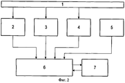
На фиг.2 показана блок-схема прибора для определения координат удаленного объекта на местности.Figure 2 shows a block diagram of a device for determining the coordinates of a remote object on the ground.
Прибор содержит устройство визирования 1 и датчики его положения в пространстве, а именно: устройство определения вертикали 2, устройство автоматического съема азимута 3, устройство автоматического съема угла места 4, устройства определения собственных координат наблюдателя 5, данные от которых поступают на обработку в устройство управления и вычислений 6 с цифровой моделью рельефа в памяти устройства управления и вычислений 6, в качестве которого может быть использован соответствующий микропроцессор. При этом устройство определения собственных координат наблюдателя 5 имеет спутниковую навигационную аппаратуру. Устройство управления и вычислений 6 своим входом и выходом соединено с приемопередатчиком в системе наблюдателя 7. Сканирование местности производят с помощью устройства приема изображения 8.The device contains a
Заявленная система определения координат удаленного объекта на местности работает следующим образом.The claimed system for determining the coordinates of a remote object on the ground works as follows.
Для определения координат удаленного объекта наблюдатель с помощью устройства приема изображения 8 производит сканирование местности через визирное устройство 1 до тех пор, пока на линии визирования А не будет зафиксирован удаленный объект, координаты которого требуется определить. В этот момент производится фиксирование показаний всех датчиков 2, 3, 4, 5, и передача данных от них в блок 6. По полученным собственным координатам устройства 5 устанавливают точку нахождения наблюдателя в пространстве цифровой модели рельефа наблюдаемой местности устройства управления и вычислений 6, а по измеренным датчиками 2, 3, 4 углам восстанавливают положение линии визирования А над цифровой моделью рельефа наблюдаемой местности устройства управления и вычислений 6 и вычисляют дальность до объекта как точки пересечения восстановленной линии визирования и цифровой модели рельефа. Координаты объекта вычисляются устройством 6 по полному набору полярных координат или как координаты точки пересечения восстановленной линии визирования с цифровой моделью рельефа. Приемопередатчик 7 служит для связи наблюдателя с центральным пунктом управления и передачи полученных данных наблюдения.To determine the coordinates of a remote object, the observer, using the image pickup device 8, scans the terrain through the
Примеры применения предлагаемого изобретения.Examples of the application of the invention.
В качестве устройства визирования 1 используется прицел стрелкового оружия, например автомата. Датчики 2, 3, 4 смонтированы на нем же. В состав датчиков 3 и 4 входят две компоненты: микромеханическая компонента позволяет зафиксировать, непродолжительное время сохранять с необходимой точностью направление на выбранный на местности или созданный искусственно репер (ориентир), и составляющая, измеряющая относительный угол между целью и репером (ориентиром).As the device of
Устройства 5, 6 входят в состав экипировки бойца-наблюдателя, и устройство 6 подключено к его индивидуальной радиостанции. Такой боец-наблюдатель способен передавать целеуказания и практически не отличим от других солдат.
В качестве устройства визирования 1 используется оптическая ось порогового, например, инфракрасного датчика, установленного на дистанционно пилотируемом летательном аппарате. Датчики 2, 3, 4, 5 смонтированы на нем же и позволяют осуществлять сканирование в плоскости, перпендикулярной направлению полета, и фиксировать положение линии визирования при превышениях порогового значения излучения. Устройство 6 расположено на земле. Такое устройство, в частности, является технической основой для организации дешевого мониторинга пожароопасных участков и раннего оповещения об очагах пожаров, если применен пороговый датчик инфракрасного излучения.As the
Тем самым при фиксировании в поле наблюдения прибора объекта наблюдения появляется возможность провести без излучения каких-либо измерительных сигналов, то есть без демаскировки наблюдателя, измерение углов на наблюдаемый объект и вычисление координат объекта с использованием наряду с устройством визирования 1 блока управления и вычислений 6.Thus, when fixing the object of observation in the field of observation of the device, it becomes possible to carry out without measuring any measurement signals, that is, without unmasking the observer, measure the angles to the observed object and calculate the coordinates of the object using, along with the
Claims (4)
Priority Applications (1)
| Application Number | Priority Date | Filing Date | Title |
|---|---|---|---|
| RU2002117002/28A RU2242019C2 (en) | 2002-06-26 | 2002-06-26 | Method for determination of co-ordinates of distant object on terrain and device for its realization |
Applications Claiming Priority (1)
| Application Number | Priority Date | Filing Date | Title |
|---|---|---|---|
| RU2002117002/28A RU2242019C2 (en) | 2002-06-26 | 2002-06-26 | Method for determination of co-ordinates of distant object on terrain and device for its realization |
Publications (2)
| Publication Number | Publication Date |
|---|---|
| RU2002117002A RU2002117002A (en) | 2004-02-20 |
| RU2242019C2 true RU2242019C2 (en) | 2004-12-10 |
Family
ID=34387087
Family Applications (1)
| Application Number | Title | Priority Date | Filing Date |
|---|---|---|---|
| RU2002117002/28A RU2242019C2 (en) | 2002-06-26 | 2002-06-26 | Method for determination of co-ordinates of distant object on terrain and device for its realization |
Country Status (1)
| Country | Link |
|---|---|
| RU (1) | RU2242019C2 (en) |
Cited By (6)
| Publication number | Priority date | Publication date | Assignee | Title |
|---|---|---|---|---|
| RU2468382C1 (en) * | 2011-05-24 | 2012-11-27 | Открытое Акционерное Общество "Производственное Объединение "Уральский Оптико-Механический Завод" Имени Э.С. Яламова" (Оао "По "Уомз") | Method to generate control signal in tracking system |
| RU2667167C1 (en) * | 2017-10-19 | 2018-09-17 | Акционерное общество "Научно-производственное предприятие "Дельта" | Method of artillery shell correction |
| RU2695041C1 (en) * | 2018-08-27 | 2019-07-18 | Публичное акционерное общество "Ракетно-космическая корпорация "Энергия" имени С.П. Королёва" | Method of orienting movable equipment on board manned spacecraft |
| RU2695046C1 (en) * | 2018-08-07 | 2019-07-18 | Публичное акционерное общество "Ракетно-космическая корпорация "Энергия" имени С.П. Королёва" | Method of orienting equipment on board manned spacecraft |
| RU2695254C1 (en) * | 2018-08-09 | 2019-07-22 | Публичное акционерное общество "Ракетно-космическая корпорация "Энергия" имени С.П. Королёва" | Navigation system for moved equipment on board of manned spacecraft |
| RU2695960C1 (en) * | 2018-08-21 | 2019-07-29 | Публичное акционерное общество "Ракетно-космическая корпорация "Энергия" имени С.П. Королёва" | Navigation system for movable on-board manned spacecraft equipment |
-
2002
- 2002-06-26 RU RU2002117002/28A patent/RU2242019C2/en not_active IP Right Cessation
Cited By (6)
| Publication number | Priority date | Publication date | Assignee | Title |
|---|---|---|---|---|
| RU2468382C1 (en) * | 2011-05-24 | 2012-11-27 | Открытое Акционерное Общество "Производственное Объединение "Уральский Оптико-Механический Завод" Имени Э.С. Яламова" (Оао "По "Уомз") | Method to generate control signal in tracking system |
| RU2667167C1 (en) * | 2017-10-19 | 2018-09-17 | Акционерное общество "Научно-производственное предприятие "Дельта" | Method of artillery shell correction |
| RU2695046C1 (en) * | 2018-08-07 | 2019-07-18 | Публичное акционерное общество "Ракетно-космическая корпорация "Энергия" имени С.П. Королёва" | Method of orienting equipment on board manned spacecraft |
| RU2695254C1 (en) * | 2018-08-09 | 2019-07-22 | Публичное акционерное общество "Ракетно-космическая корпорация "Энергия" имени С.П. Королёва" | Navigation system for moved equipment on board of manned spacecraft |
| RU2695960C1 (en) * | 2018-08-21 | 2019-07-29 | Публичное акционерное общество "Ракетно-космическая корпорация "Энергия" имени С.П. Королёва" | Navigation system for movable on-board manned spacecraft equipment |
| RU2695041C1 (en) * | 2018-08-27 | 2019-07-18 | Публичное акционерное общество "Ракетно-космическая корпорация "Энергия" имени С.П. Королёва" | Method of orienting movable equipment on board manned spacecraft |
Also Published As
| Publication number | Publication date |
|---|---|
| RU2002117002A (en) | 2004-02-20 |
Similar Documents
| Publication | Publication Date | Title |
|---|---|---|
| US10209342B2 (en) | Electromagnetic radiation source locating system | |
| US10704863B1 (en) | System for tracking a presumed target using network-connected lead and follower scopes, and scope for configured for use in the system | |
| US8020769B2 (en) | Handheld automatic target acquisition system | |
| US8868342B2 (en) | Orientation device and method | |
| US5034812A (en) | Image processing utilizing an object data store to determine information about a viewed object | |
| EP1949016B1 (en) | Precision targeting | |
| US10408574B2 (en) | Compact laser and geolocating targeting system | |
| CN102749659B (en) | Multifunctional photoelectric detection instrument and target position observing and determining method implemented by same | |
| US6281841B1 (en) | Direction determining apparatus | |
| US6388611B1 (en) | Method and system for dynamic surveillance of a remote object using GPS | |
| JP2001518627A (en) | Targeting system based on radio frequency interferometer and laser rangefinder / indicator | |
| CN104457744A (en) | Handheld target detector and detection method and trajectory calculation method thereof | |
| CN113424012B (en) | In-vehicle device with network-connected scope to allow multiple other devices to track a target simultaneously | |
| CN204388861U (en) | Hand-held target detecting instrument | |
| KR100963680B1 (en) | Apparatus and method for measuring remote target's axis using gps | |
| RU2242019C2 (en) | Method for determination of co-ordinates of distant object on terrain and device for its realization | |
| RU2247921C2 (en) | Method for finding one's bearings on the ground and device for its realization | |
| US20160033268A1 (en) | Apparatus for augmented reality for optical systems | |
| US10288738B1 (en) | Precision mobile baseline determination device and related method | |
| JP2001066097A (en) | Auxiliary sighting unit for small arms | |
| RU2717138C1 (en) | System of portable sets for automated target designation on the battlefield | |
| US5367333A (en) | Passive range measurement system | |
| RU2167380C2 (en) | Automated guidance and fire control system of salvo fire rocket artillery combat vehicle (modifications) | |
| RU2247941C2 (en) | Optical system for determining co-ordinates of object | |
| RU2381447C1 (en) | Spherical positioner for remote object and method for afield positioning of remote object |
Legal Events
| Date | Code | Title | Description |
|---|---|---|---|
| PC41 | Official registration of the transfer of exclusive right |
Effective date: 20121219 |
|
| MM4A | The patent is invalid due to non-payment of fees |
Effective date: 20130627 |