RU2236734C2 - Method for manufacturing electrical machine commutators - Google Patents
Method for manufacturing electrical machine commutators Download PDFInfo
- Publication number
- RU2236734C2 RU2236734C2 RU2002109423/09A RU2002109423A RU2236734C2 RU 2236734 C2 RU2236734 C2 RU 2236734C2 RU 2002109423/09 A RU2002109423/09 A RU 2002109423/09A RU 2002109423 A RU2002109423 A RU 2002109423A RU 2236734 C2 RU2236734 C2 RU 2236734C2
- Authority
- RU
- Russia
- Prior art keywords
- current
- collector
- commutator
- stage
- plates
- Prior art date
Links
Images
Landscapes
- Motor Or Generator Current Collectors (AREA)
Abstract
Description
Изобретение относится к электротехнике и может быть использовано для изготовления продороженных коллекторов электрических машин.The invention relates to electrical engineering and can be used for the manufacture of expensive collectors of electrical machines.
Известен “Способ изготовления коллекторов электрических машин” (патент РФ №2079196, H 01 R 43/06, 1997 г.), включающий сборку заготовки коллектора с помощью технологического кольца с радиальными выступами путем размещения в нем коллекторных и изоляционных пластин, при этом между токоведущими пластинами образуются зазоры, являющиеся шлицами в готовом коллекторе, установку технологического кольца с заготовкой коллектора в матрице пресс-формы и опрессовку заготовки коллектора в два этапа.The known “Method for the manufacture of collectors of electrical machines” (RF patent No. 2079196, H 01 R 43/06, 1997), comprising assembling a collector blank using a process ring with radial protrusions by placing collector and insulating plates in it, while between current-carrying the plates form gaps, which are slots in the finished collector, installation of the process ring with the collector blank in the mold matrix, and crimping the collector blank in two stages.
Учитывая особенности конструкции технологического кольца для сборки заготовки коллектора, данным способом возможно изготовить продороженный коллектор, но без явно выраженного арочного распора, что отрицательно скажется на жесткости конструкции коллектора.Given the design features of the process ring for the assembly of the collector blank, using this method it is possible to produce an expensive collector, but without a pronounced arched spacer, which will negatively affect the rigidity of the collector design.
Арочный распор имеет место в коллекторе, изготовляемом по выбранному за прототип “Способу изготовления коллекторов электрических машин” (патент РФ №2041539, H 01 R 43/06, 1995 г.), включающему сборку (набор и перепрессовку) элементов заготовки коллектора: токоведущих пластин с “ласточкиным хвостом” и изоляционных пластин, осуществляемую в кольце-матрице пресс-формы и дальнейшую опрессовку заготовки в пресс-форме.An arched strut takes place in a collector manufactured according to the “Method for the manufacture of collectors of electric machines” selected for the prototype (RF patent No. 2041539, H 01 R 43/06, 1995), including assembly (set and re-pressing) of collector blank elements: current-carrying plates with a “dovetail” and insulating plates, carried out in the ring-matrix of the mold and further crimping the workpiece in the mold.
К недостаткам этого способа относятся: невозможность изготовления продороженного коллектора (требуется фрезерование изоляционных пластин на поверхности готового коллектора); в процессе сборки элементов заготовки коллектора происходят колебания токоведущих и изоляционных пластин, что приводит к смещению их друг относительно друга, а далее, в процессе опрессовки токоведущие пластины деформируются и, соответственно, деформируют и частично разрушают хрупкие изоляционные пластины, что значительно снижает величину арочного распора в коллекторе и делает арочный распор неравномерным по плоскости прилегания пластин, это также отрицательно сказывается на жесткости коллектора; в процессе работы при нагревании изготовленного данным способом коллектора в корпусе последнего возникают перегрузки, что способствует возможности проявления “термического удара” корпуса коллектора от пластин, т.е. подъему отдельных токоведущих пластин и, соответственно, выходу из строя коллектора.The disadvantages of this method include: the inability to manufacture an expensive collector (milling of insulating plates on the surface of the finished collector is required); during assembly of the collector blank elements, vibrations of current-carrying and insulating plates occur, which leads to their displacement relative to each other, and then, during crimping, current-carrying plates are deformed and, accordingly, deform and partially destroy brittle insulating plates, which significantly reduces the size of the arch the collector and makes the arched strut uneven along the plane of contact of the plates, this also negatively affects the stiffness of the collector; during operation, when the collector manufactured by this method is heated, overloads occur in the housing of the latter, which contributes to the possibility of a “thermal shock” of the collector housing from the plates, i.e. the rise of individual current-carrying plates and, accordingly, the failure of the collector.
Задачей изобретения является разработка более технологичного способа изготовления продороженных коллекторов с высокими прочностными характеристиками за счет равнопрочности крепления элементов заготовки коллектора при создании равномерного усиленного арочного распора в ней и повышенной надежностью в эксплуатации за счет нанесения защитного слоя на элементы заготовки коллектора.The objective of the invention is to develop a more technological method for the manufacture of expensive collectors with high strength characteristics due to the equal strength of the fastening elements of the collector blank while creating a uniform reinforced arched spacer in it and increased operational reliability by applying a protective layer to the collector blank elements.
Поставленная задача решается тем, что в способе изготовления коллекторов электрических машин, включающем сборку и дальнейшую опрессовку элементов заготовки коллектора: токоведущих пластин с “ласточкиным хвостом” и изоляционных пластин в кольце-матрице пресс-формы, сборку элементов заготовки коллектора осуществляют в три этапа, при этом на первом этапе концы “ласточкиного хвоста” с обеих сторон токоведущих пластин одновременно отгибают в направлении оси кольца-матрицы, на втором этапе извлекают элементы заготовки коллектора из кольца-матрицы и наносят в зазоры на внешней поверхности токоведущих пластин быстросмываемое пастообразное вещество, а на третьем этапе элементы заготовки коллектора заново устанавливают в кольцо-матрицу и на боковые и внутреннюю поверхности токоведущих и изоляционных пластин наносят термостойкое вещество.The problem is solved in that in a method of manufacturing collectors of electrical machines, including the assembly and further crimping of the collector blank elements: current-carrying plates with a “dovetail” and insulating plates in the mold matrix ring, the collector blank assembly is carried out in three stages, with at the first stage, the ends of the “dovetail” on both sides of the current-carrying plates are simultaneously bent in the direction of the axis of the matrix ring, at the second stage, collector blank elements are removed from the The dyes are matrices and are applied to the gaps on the outer surface of the current-carrying plates with a quick-release pasty substance, and at the third stage, the collector blank elements are reinstalled in the matrix ring and a heat-resistant substance is applied to the side and inner surfaces of the current-carrying and insulating plates.
Концы “ласточкиного хвоста” токоведущих пластин отгибают в направлении оси кольца-матрицы для усиления арочного распора в заготовке коллектора.The ends of the dovetail of the current-carrying plates are bent in the direction of the axis of the matrix ring to enhance the arched spacing in the collector blank.
Концы “ласточкиного хвоста” отгибают с обеих сторон токоведущих пластин одновременно с целью выравнивания арочного распора в заготовке коллектора.The ends of the “dovetail” are bent on both sides of the current-carrying plates at the same time in order to align the arched spacing in the collector blank.
Элементы заготовки коллектора извлекают из кольца-матрицы для получения доступа к зазорам на внешней поверхности токоведущих пластин.The collector blank elements are removed from the matrix ring to gain access to the gaps on the outer surface of the current-carrying plates.
В зазоры на внешней поверхности токоведущих пластин наносят быстросмываемое пастообразное вещество с целью предотвращения смещения изоляционных пластин в процессе опрессовки заготовки коллектора и во избежание попадания текучего компонента пластмасс в зазоры.A quick-release paste-like substance is applied to the gaps on the outer surface of the current-carrying plates in order to prevent the displacement of the insulating plates during the crimping of the collector blank and to prevent the fluid component of plastics from entering the gaps.
Наносимое в зазоры вещество выполнено быстросмываемым для легкого удаления вещества с помощью жидкой среды после опрессовки заготовки коллектора.The substance applied to the gaps is quick-washable for easy removal of the substance using a liquid medium after crimping the collector blank.
Элементы заготовки коллектора заново устанавливают в кольцо-матрицу с целью удержания их в собранном состоянии перед выполнением следующей операции.The collector blank elements are reinstalled into the matrix ring in order to keep them assembled before performing the next operation.
На боковые и внутреннюю поверхности токоведущих пластин наносят термическое вещество с целью соединения двух видов пластин заготовки коллектора и создания защитного слоя от “термического удара” (перегрузок) корпуса коллектора от пластин.Thermal substance is applied to the side and inner surfaces of the current-carrying plates in order to connect the two types of collector blank plates and create a protective layer from “thermal shock” (overloads) of the collector body from the plates.
фиг.1 - продольный разрез кольца-матрицы с заготовкой коллектора на первом этапе сборки элементов заготовки;figure 1 is a longitudinal section of the ring matrix with the workpiece of the collector at the first stage of assembly of the elements of the workpiece;
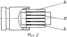
фиг.2 - кольцо-матрица с заготовкой коллектора на втором этапе сборки ее элементов;figure 2 - the matrix ring with the workpiece of the collector at the second stage of assembly of its elements;
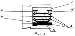
фиг.3 - продольный разрез кольца-матрицы с заготовкой коллектора на третьем этапе сборки элементов заготовки.figure 3 is a longitudinal section of the matrix ring with the workpiece of the collector at the third stage of assembly of the elements of the workpiece.
Изобретение реализуют следующим образом. Элементы заготовки коллектора: токоведущие пластины 1 с “ласточкиным хвостом” 2 и изоляционные пластины 3 размещают в кольце-матрице 4. На первом этапе (фиг.1) сборки элементов заготовки коллектора концы 5 “ласточкиного хвоста” 2 с обеих сторон токоведущих пластин 1 одновременно отгибают, в данном случае посредством воздействия на концы 5 втулками 6 с коническими отверстиями 7, в направлении оси кольца-матрицы 4, тем самым усиливая и выравнивая арочный распор в заготовке коллектора за счет деформации его пластин. Далее, на втором этапе (фиг.2) элементы заготовки коллектора вместе с втулками 6 извлекают полностью или на длину зазора 8 на внешней поверхности 9 токоведущих пластин 1 и наносят в зазоры 8 быстросмываемое пастообразное вещество 10. На третьем этапе (фиг.3) элементы заготовки коллектора заново устанавливают в кольцо-матрицу 4, извлекают втулки 6 и наносят на боковые 11 и внутреннюю 12 поверхности токоведущих 1 и изоляционных 3 пластин термостойкое вещество (не показано).The invention is implemented as follows. Elements of the collector blank: current-carrying
После выполнения всех этапов сборки элементы заготовки коллектора опрессовывают в пресс-форме по технологии согласно прототипу.After performing all stages of the assembly, the elements of the collector blank are pressed in the mold according to the technology according to the prototype.
По окончании прессования готовый коллектор извлекают из кольца-матрицы 4 и помещают в жидкую среду для быстрого смыва пастообразного вещества из зазоров 8.At the end of pressing, the finished collector is removed from the matrix ring 4 and placed in a liquid medium for quick flushing of the pasty substance from the
Предлагаемый способ изготовления коллекторов электрических машин прост и технологичен, с его помощью получают надежные в работе продороженные коллекторы с высокими прочностными характеристиками.The proposed method for the manufacture of collectors of electrical machines is simple and technologically advanced, with its help reliable road collectors with high strength characteristics are reliable.
Claims (1)
Priority Applications (1)
| Application Number | Priority Date | Filing Date | Title |
|---|---|---|---|
| RU2002109423/09A RU2236734C2 (en) | 2002-04-12 | 2002-04-12 | Method for manufacturing electrical machine commutators |
Applications Claiming Priority (1)
| Application Number | Priority Date | Filing Date | Title |
|---|---|---|---|
| RU2002109423/09A RU2236734C2 (en) | 2002-04-12 | 2002-04-12 | Method for manufacturing electrical machine commutators |
Publications (2)
| Publication Number | Publication Date |
|---|---|
| RU2002109423A RU2002109423A (en) | 2003-11-20 |
| RU2236734C2 true RU2236734C2 (en) | 2004-09-20 |
Family
ID=33432762
Family Applications (1)
| Application Number | Title | Priority Date | Filing Date |
|---|---|---|---|
| RU2002109423/09A RU2236734C2 (en) | 2002-04-12 | 2002-04-12 | Method for manufacturing electrical machine commutators |
Country Status (1)
| Country | Link |
|---|---|
| RU (1) | RU2236734C2 (en) |
Citations (5)
| Publication number | Priority date | Publication date | Assignee | Title |
|---|---|---|---|---|
| DE1231799B (en) * | 1961-12-08 | 1967-01-05 | Siemens Ag | Method for manufacturing a commutator for electrical machines |
| FR2585521B1 (en) * | 1985-07-26 | 1987-11-20 | Bruss Respub Nauc | METHOD FOR MANUFACTURING ELECTRIC MACHINE COLLECTORS AND COLLECTORS OBTAINED BY SAID METHOD |
| EP0546317B1 (en) * | 1991-12-09 | 1995-02-15 | KOLEKTOR d.o.o. | Method for manufacturing a moulded flat commutator |
| RU2041539C1 (en) * | 1992-06-16 | 1995-08-09 | Виктор Федорович Зорин | Method of manufacturing collectors of electric machines and press mold for manufacturing |
| RU2079196C1 (en) * | 1995-08-08 | 1997-05-10 | Игорь Викторович Зорин | Method for production of commutators for electric machines and press mold for this method |
-
2002
- 2002-04-12 RU RU2002109423/09A patent/RU2236734C2/en not_active IP Right Cessation
Patent Citations (5)
| Publication number | Priority date | Publication date | Assignee | Title |
|---|---|---|---|---|
| DE1231799B (en) * | 1961-12-08 | 1967-01-05 | Siemens Ag | Method for manufacturing a commutator for electrical machines |
| FR2585521B1 (en) * | 1985-07-26 | 1987-11-20 | Bruss Respub Nauc | METHOD FOR MANUFACTURING ELECTRIC MACHINE COLLECTORS AND COLLECTORS OBTAINED BY SAID METHOD |
| EP0546317B1 (en) * | 1991-12-09 | 1995-02-15 | KOLEKTOR d.o.o. | Method for manufacturing a moulded flat commutator |
| RU2041539C1 (en) * | 1992-06-16 | 1995-08-09 | Виктор Федорович Зорин | Method of manufacturing collectors of electric machines and press mold for manufacturing |
| RU2079196C1 (en) * | 1995-08-08 | 1997-05-10 | Игорь Викторович Зорин | Method for production of commutators for electric machines and press mold for this method |
Similar Documents
| Publication | Publication Date | Title |
|---|---|---|
| EP1116316B1 (en) | An electric motor rotor and a method for producing an electric motor rotor | |
| US20100213675A1 (en) | Method Of Manufacture Of Compliant Plate Seals | |
| CN100400222C (en) | Method of manufacturing hollow blades for turbines | |
| US6276899B1 (en) | Impeller manufacturing process | |
| CN111503155B (en) | Method for producing a bearing body of a sliding bearing arrangement and bearing body | |
| JPS5950226A (en) | Slide bearing | |
| US4884951A (en) | Method of clamping blades | |
| RU2236734C2 (en) | Method for manufacturing electrical machine commutators | |
| US3478421A (en) | Method of manufacturing commutators | |
| RU2604661C2 (en) | Method of repairing stator | |
| JP4335536B2 (en) | Equipment for machining annular workpieces | |
| CA2736435A1 (en) | Method and apparatus for manufacturing a rotor | |
| CN1525624B (en) | Motors with laminated rotors | |
| CN115250018A (en) | Core discs or laminated cores for rotors of electric motors | |
| WO2005050820A1 (en) | Commutator for an electric machine | |
| EP2055897A1 (en) | Flexible Shims | |
| DE102006021696B4 (en) | Method for producing a rotor of a dynamoelectric machine and rotor of a dynamoelectric machine | |
| JP6328300B2 (en) | Generator stator bar having deformed strip and process for producing generator stator bar | |
| EP4249758B1 (en) | Assembled shaft and method for manufacturing an assembled shaft | |
| JP2004263687A5 (en) | ||
| RU2079196C1 (en) | Method for production of commutators for electric machines and press mold for this method | |
| JP5103000B2 (en) | Magnet molding method of rotor core and jig therefor | |
| KR20040071232A (en) | Solder ring for production of vacuum tube and method for the production of such a solder ring and of a vacuum tube | |
| JPS6113144Y2 (en) | ||
| WO2021170328A1 (en) | Assembly-optimised coolant pump |
Legal Events
| Date | Code | Title | Description |
|---|---|---|---|
| MM4A | The patent is invalid due to non-payment of fees |
Effective date: 20070413 |