RU2236282C1 - Apparatus for cleaning gas from liquid and solid admixtures - Google Patents
Apparatus for cleaning gas from liquid and solid admixtures Download PDFInfo
- Publication number
- RU2236282C1 RU2236282C1 RU2003116949/15A RU2003116949A RU2236282C1 RU 2236282 C1 RU2236282 C1 RU 2236282C1 RU 2003116949/15 A RU2003116949/15 A RU 2003116949/15A RU 2003116949 A RU2003116949 A RU 2003116949A RU 2236282 C1 RU2236282 C1 RU 2236282C1
- Authority
- RU
- Russia
- Prior art keywords
- liquid
- gas
- stacks
- cleaning gas
- sizes
- Prior art date
Links
- 238000004140 cleaning Methods 0.000 title claims abstract description 7
- 239000007788 liquid Substances 0.000 title claims description 11
- 239000007787 solid Substances 0.000 title claims description 10
- 239000012535 impurity Substances 0.000 claims description 8
- 238000000926 separation method Methods 0.000 claims description 8
- 238000004519 manufacturing process Methods 0.000 abstract description 4
- 238000009434 installation Methods 0.000 abstract description 3
- 239000000126 substance Substances 0.000 abstract description 3
- 238000000034 method Methods 0.000 abstract 1
- 239000007789 gas Substances 0.000 description 16
- 210000001520 comb Anatomy 0.000 description 2
- 210000002445 nipple Anatomy 0.000 description 2
- 239000006096 absorbing agent Substances 0.000 description 1
- 230000007797 corrosion Effects 0.000 description 1
- 238000005260 corrosion Methods 0.000 description 1
- 230000006378 damage Effects 0.000 description 1
- 230000003247 decreasing effect Effects 0.000 description 1
- 239000003921 oil Substances 0.000 description 1
- 239000002245 particle Substances 0.000 description 1
- 238000000746 purification Methods 0.000 description 1
- 238000003466 welding Methods 0.000 description 1
Images
Landscapes
- Separating Particles In Gases By Inertia (AREA)
Abstract
Description
Изобретение относится к устройствам для отделения жидких и твердых примесей от газа. Изобретение может быть использовано в нефтяной, газовой, химической и других отраслях промышленности.The invention relates to devices for separating liquid and solid impurities from gas. The invention can be used in the oil, gas, chemical and other industries.
Известен сепаратор для очистки газов от механических примесей и жидкости, включающий цилиндрический корпус и установленные в нем поддон со сливной трубой и крышку, между которыми расположен пакет жалюзийных радиальных гофрированных пластин с переменной высотой гофр, увеличивающейся в направлении движения газового потока [1]. Крышка выполнена с центральным отверстием и имеет диаметр, равный диаметру корпуса сепаратора, а поддон выполнен диаметром, меньшим диаметра корпуса, и образует с ним кольцевой канал для прохождения газового потока. Ширина оснований гофр выполнена уменьшающейся от периферии к центру.A known separator for cleaning gases from mechanical impurities and liquids, including a cylindrical body and a tray with a drain pipe and a lid installed in it, between which there is a packet of louvered radial corrugated plates with a variable height of corrugations increasing in the direction of gas flow [1]. The cover is made with a Central hole and has a diameter equal to the diameter of the separator housing, and the pan is made with a diameter smaller than the diameter of the housing, and forms with it an annular channel for the passage of gas flow. The width of the corrugation bases is made decreasing from the periphery to the center.
Недостатком данной конструкции является сложность сборки гофрированных пластин с переменной высотой гофр в кольцевой жалюзийный пакет и прикрепления пластин по торцам к крышке и поддону, а также неремонтопригодность конструкции, т.к. в случае забивания каналов гофрированных пластин или их частичного разрушения (коррозии, поломки и т.п.) необходимо разрезать корпус сепаратора и заново изготавливать и монтировать в аппарате кольцевой пакет.The disadvantage of this design is the difficulty of assembling the corrugated plates with a variable height of the corrugations in an annular louvre bag and attaching the plates at the ends to the lid and pallet, as well as the non-repairability of the structure, as in the case of clogging of the corrugated plate channels or their partial destruction (corrosion, breakage, etc.), it is necessary to cut the separator body and re-manufacture and mount the ring package in the apparatus.
Известна конструкция газосепаратора жалюзийного для очистки газа от жидких и твердых примесей, содержащего вертикальный корпус с входным и выходным штуцерами и отбойник из жалюзийных пластин волнообразного профиля, собранных в кольцевую секцию [2], принятый за прототип. Кольцевая секция состоит из нижнего кольца, наружный диаметр которого равен внутреннему диаметру корпуса сепаратора, и верхней крышки, диаметр которой на приблизительно 200 мм меньше диаметра корпуса сепаратора. На нижнем кольце концентрично приварены две кольцевые гребенки, прорези в которых выполнены так, чтобы после установки в них нижних торцов жалюзийных пластин между пластинами образовались волнообразные каналы. В прорези верхних торцов жалюзийных пластин устанавливают концентрично нижним такие же две гребенки, а на них верхнюю крышку. Кольцевая секция из жалюзийных пластин установлена в обечайке сепаратора, причем ее нижнее кольцо по наружному диаметру приварено к обечайке. При прохождении газа через волнообразные каналы между жалюзийными пластинами за счет сил инерции происходит отделение от газа более тяжелых жидких и твердых примесей. Очищенный газ через кольцевой зазор между корпусом сепаратора и верхней крышкой выходит через выходной штуцер из аппарата.A known design of a louvered gas separator for cleaning gas from liquid and solid impurities, comprising a vertical housing with inlet and outlet fittings and a chipper from louvre plates of a wave-like profile assembled in an annular section [2], adopted as a prototype. The annular section consists of a lower ring, the outer diameter of which is equal to the inner diameter of the separator body, and an upper cover, the diameter of which is approximately 200 mm less than the diameter of the separator body. Two ring combs are welded concentrically on the lower ring, the slots in which are made so that after installing the lower ends of the louvre plates in them, wave-like channels are formed between the plates. In the slot of the upper ends of the louvre plates, the same two combs are installed concentrically with the lower one, and the upper cover is placed on them. An annular section of louvre plates is installed in the cage of the separator, and its lower ring is welded to the casing along the outer diameter. When gas passes through the wave-like channels between the louvre plates due to inertia forces, separation of heavier liquid and solid impurities from the gas occurs. The purified gas through the annular gap between the separator housing and the top cover leaves through the outlet fitting from the apparatus.
Недостатками данной конструкции жалюзийного сепаратора являются сложность и трудоемкость сборки кольцевой секции, ее неразборность после установки в аппарат, делающие его неремонтопригодным.The disadvantages of this design of the louvre separator are the complexity and complexity of the assembly of the annular section, its inseparability after installation in the apparatus, making it non-repairable.
Задачей данного изобретения является повышение технологичности изготовления и монтажа аппарата для очистки газа от жидких и твердых примесей, его ремонтопригодность.The objective of the invention is to increase the manufacturability of the manufacture and installation of apparatus for cleaning gas from liquid and solid impurities, its maintainability.
Поставленная задача решается за счет того, что в аппарате, содержащем корпус с входным и выходным штуцерами, верхнюю крышку, соединенную с выходным штуцером, и нижнюю со сливной трубой, штатным люком-лазом для монтажа-демонтажа сепарационных элементов жалюзийного типа, между верхней и нижней крышками установлен сварной прямоугольный каркас с гнездами-нишами, в которых закреплены с возможностью замены жалюзийные пакеты в прямоугольных рамах.The problem is solved due to the fact that in the apparatus containing the housing with inlet and outlet fittings, the upper cover connected to the output fitting, and the bottom with a drain pipe, a standard manhole for mounting and dismounting the louvre-type separation elements, between the upper and lower the lids are fitted with a welded rectangular frame with nests-niches in which louvred bags in rectangular frames are fixed with the possibility of replacement.
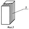
Каждый жалюзийный пакет выполнен в виде пространственной решетки, которая собрана из волнообразных пластинчатых элементов (жалюзийных пластин), собранных в пакет с определенным шагом и закрепленных (на сварке) в прямоугольной раме. Размер прямоугольной рамы сепарационного пакета унифицирован и определяется возможностью транспортировки сепарационного пакета внутрь корпуса аппарата для монтажа-демонтажа через штатный люк-лаз аппарата. Размер боковых сторон сварного прямоугольного каркаса, а соответственно число сепарационных пакетов, размещаемых в гнездах-нишах каркаса, определяется расходом газообразной среды через аппарат.Each louvre bag is made in the form of a spatial lattice, which is assembled from wave-shaped plate elements (louvre plates), assembled into a bag with a certain step and fixed (on welding) in a rectangular frame. The size of the rectangular frame of the separation bag is unified and is determined by the possibility of transporting the separation bag inside the apparatus for mounting-dismantling through the standard hatch-hole of the apparatus. The size of the sides of the welded rectangular frame, and accordingly the number of separation bags placed in the niches of the frame, is determined by the flow rate of the gaseous medium through the apparatus.
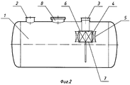
На фиг.1 схематично показан предлагаемый аппарат вертикального типа, продольный разрез, на фиг.2 - предлагаемый аппарат горизонтального типа, продольный разрез, на фиг.3 - конструкция пакета из жалюзийных пластин, собранных с определенным шагом и закрепленных в прямоугольной раме.Figure 1 schematically shows the proposed apparatus of the vertical type, longitudinal section, figure 2 - the proposed apparatus of the horizontal type, longitudinal section, figure 3 - the design of the package of louvre plates assembled with a certain step and fixed in a rectangular frame.
Конструкция предлагаемого аппарата включает корпус 1, входной штуцер 2, выходной штуцер 3, прямоугольный каркас с гнездами-нишами 4, жалюзийные пакеты 5, верхнюю 6 и нижнюю 7 крышки, штатный люк-лаз 8.The design of the proposed apparatus includes a
Аппарат работает следующим образом.The device operates as follows.
Газ входит в аппарат через входной штуцер 2, проходит через жалюзийные пакеты 5, установленные в прямоугольном каркасе с гнездами-нишами 4, и через выходной штуцер 3 выходит из аппарата. При прохождении газа через криволинейные каналы жалюзийных пакетов происходит отделение от газа более тяжелых жидких и твердых частиц. Твердые частицы вымываются отсепарированной жидкостью и потоком газа из криволинейных каналов в нижнюю часть каркаса и далее через дренажную трубу в нижнюю часть аппарата.Gas enters the apparatus through the
Предлагаемый сварной прямоугольный каркас с верхней и нижней крышками может устанавливаться как в существующих аппаратах (при реконструкции вышедших из строя или неэффективных аппаратов), так и при проектировании и изготовлении новых аппаратов (сепараторов, колонн, абсорберов и т.п.), где требуется качественная очистка газообразных сред от жидких и твердых примесей.The proposed welded rectangular frame with upper and lower covers can be installed both in existing devices (during the reconstruction of failed or inefficient devices), and in the design and manufacture of new devices (separators, columns, absorbers, etc.), where high-quality purification of gaseous media from liquid and solid impurities.
Источники информацииSources of information
1. А.с. СССР №1634300, кл. B 01 D 45/06, опубл. 15.03.91, БИ №10.1. A.S. USSR No. 1634300, cl. B 01 D 45/06, publ. 03/15/91, BI No. 10.
2. Отраслевой стандарт. Газосепараторы центробежные регулируемые, жалюзийные и сетчатые. ОСТ 26-02-645-72. ГЛАВНЕФТЕХИММАШ, Москва, 1972 г., с.19-27 (прототип).2. Industry standard. Gas separators are centrifugal adjustable, louvered and mesh. OST 26-02-645-72. GLAVNEFTEKHIMMASH, Moscow, 1972, p.19-27 (prototype).
Claims (2)
Priority Applications (1)
| Application Number | Priority Date | Filing Date | Title |
|---|---|---|---|
| RU2003116949/15A RU2236282C1 (en) | 2003-05-29 | 2003-05-29 | Apparatus for cleaning gas from liquid and solid admixtures |
Applications Claiming Priority (1)
| Application Number | Priority Date | Filing Date | Title |
|---|---|---|---|
| RU2003116949/15A RU2236282C1 (en) | 2003-05-29 | 2003-05-29 | Apparatus for cleaning gas from liquid and solid admixtures |
Publications (2)
| Publication Number | Publication Date |
|---|---|
| RU2236282C1 true RU2236282C1 (en) | 2004-09-20 |
| RU2003116949A RU2003116949A (en) | 2004-12-20 |
Family
ID=33433977
Family Applications (1)
| Application Number | Title | Priority Date | Filing Date |
|---|---|---|---|
| RU2003116949/15A RU2236282C1 (en) | 2003-05-29 | 2003-05-29 | Apparatus for cleaning gas from liquid and solid admixtures |
Country Status (1)
| Country | Link |
|---|---|
| RU (1) | RU2236282C1 (en) |
Cited By (4)
| Publication number | Priority date | Publication date | Assignee | Title |
|---|---|---|---|---|
| RU2310497C1 (en) * | 2006-04-19 | 2007-11-20 | Валерий Григорьевич Биндас | Method of improving separation unit of gas separator and gas separator |
| RU2440173C2 (en) * | 2010-04-13 | 2012-01-20 | Общество с ограниченной ответственностью "Научно-исследовательский и проектно-конструкторский институт химического машиностроения" (сокращенное фирменное наименование ООО "ЛЕННИИХИММАШ") | Louvers-type gas-fluid separator |
| RU2634653C1 (en) * | 2016-12-28 | 2017-11-02 | Общество с ограниченной ответственностью "Газпром трансгаз Екатеринбург" | Method of purifying natural gas from heavy hydrocarbons |
| RU2798104C2 (en) * | 2023-01-12 | 2023-06-15 | Евгений Валериевич Казарцев | Flare separator with cyclone droplet eliminator |
Citations (5)
| Publication number | Priority date | Publication date | Assignee | Title |
|---|---|---|---|---|
| US3720046A (en) * | 1969-06-05 | 1973-03-13 | Gen Electric | Flow distribution apparatus |
| DE2104355B2 (en) * | 1970-02-02 | 1980-02-14 | Westinghouse Electric Corp., Pittsburgh, Pa. (V.St.A.) | Device for separating water or other loads from flowing vapors and gases |
| US4492569A (en) * | 1982-03-03 | 1985-01-08 | Ingeniorfirmaet Lytzen Ks | Oven |
| SU1590107A1 (en) * | 1988-07-18 | 1990-09-07 | Ю.И.Гуркин | Filtering unit |
| SU1662630A1 (en) * | 1988-10-04 | 1991-07-15 | Научно-Производственное Гидролизное Объединение "Гидролизпром" | Mist trap |
-
2003
- 2003-05-29 RU RU2003116949/15A patent/RU2236282C1/en active
Patent Citations (5)
| Publication number | Priority date | Publication date | Assignee | Title |
|---|---|---|---|---|
| US3720046A (en) * | 1969-06-05 | 1973-03-13 | Gen Electric | Flow distribution apparatus |
| DE2104355B2 (en) * | 1970-02-02 | 1980-02-14 | Westinghouse Electric Corp., Pittsburgh, Pa. (V.St.A.) | Device for separating water or other loads from flowing vapors and gases |
| US4492569A (en) * | 1982-03-03 | 1985-01-08 | Ingeniorfirmaet Lytzen Ks | Oven |
| SU1590107A1 (en) * | 1988-07-18 | 1990-09-07 | Ю.И.Гуркин | Filtering unit |
| SU1662630A1 (en) * | 1988-10-04 | 1991-07-15 | Научно-Производственное Гидролизное Объединение "Гидролизпром" | Mist trap |
Non-Patent Citations (1)
| Title |
|---|
| Газосепараторы центробежные регулируемые, жалюзийные и сетчатые. ОСТ 26-02-645-72. - М., Главнефтехиммаш, 1972, с.19-27. * |
Cited By (4)
| Publication number | Priority date | Publication date | Assignee | Title |
|---|---|---|---|---|
| RU2310497C1 (en) * | 2006-04-19 | 2007-11-20 | Валерий Григорьевич Биндас | Method of improving separation unit of gas separator and gas separator |
| RU2440173C2 (en) * | 2010-04-13 | 2012-01-20 | Общество с ограниченной ответственностью "Научно-исследовательский и проектно-конструкторский институт химического машиностроения" (сокращенное фирменное наименование ООО "ЛЕННИИХИММАШ") | Louvers-type gas-fluid separator |
| RU2634653C1 (en) * | 2016-12-28 | 2017-11-02 | Общество с ограниченной ответственностью "Газпром трансгаз Екатеринбург" | Method of purifying natural gas from heavy hydrocarbons |
| RU2798104C2 (en) * | 2023-01-12 | 2023-06-15 | Евгений Валериевич Казарцев | Flare separator with cyclone droplet eliminator |
Similar Documents
| Publication | Publication Date | Title |
|---|---|---|
| EP1694424B1 (en) | Separator arrangement for gas/liquid separation; apparatus; and, methods | |
| JP5379792B2 (en) | Filter assembly and method | |
| JP5520800B2 (en) | Oil separator | |
| US7618472B2 (en) | Vane-type demister | |
| US8540791B2 (en) | Canister air filter and method for fabricating the same | |
| US5601626A (en) | Support construction of filter element in dust collecting apparatus | |
| CN105209733A (en) | Filtration system for a gas turbine air intake and methods | |
| CN101249357A (en) | A filter assembly | |
| CN102449119B (en) | Improved Contacting Stages for Cocurrent Contacting Devices | |
| JP6804621B1 (en) | Channel direction change type reaction by-product collection device for semiconductor processes | |
| US5112375A (en) | Radial vane demisting system in a separator for removing entrained droplets from a gas stream | |
| RU2011144376A (en) | FILTER CASSETTE, FILTER DEVICE AND GAS TURBINE WITH SUCH FILTER CASSETTE | |
| US20130219842A1 (en) | Variable length bag cage | |
| RU2236282C1 (en) | Apparatus for cleaning gas from liquid and solid admixtures | |
| CN106536021A (en) | Segmented filter assembly | |
| US12515160B2 (en) | Gas filter separator filter cartridge with keys and/or baffle | |
| US20050178718A1 (en) | Coalescing and separation arrangements systems and methods for liquid mixtures | |
| RU2440173C2 (en) | Louvers-type gas-fluid separator | |
| US20080073298A1 (en) | Filter having opposing parallel planes of wedge wires | |
| US7448501B2 (en) | Concentric C-shaped filter and screen topology | |
| JP2000508581A (en) | Disposable coalescer | |
| RU2003116949A (en) | APPARATUS FOR CLEANING GAS FROM LIQUID AND SOLID IMPURITIES | |
| US20240269601A1 (en) | Hot gas filtration with enhanced compartmental flow distribution via dual filter configurations | |
| RU2385757C1 (en) | Separator | |
| WO2018217578A2 (en) | Industrial air filtration system and associated filter element |
Legal Events
| Date | Code | Title | Description |
|---|---|---|---|
| PD4A | Correction of name of patent owner | ||
| PC4A | Invention patent assignment |
Effective date: 20080311 |
|
| PC41 | Official registration of the transfer of exclusive right |
Effective date: 20180731 |