RU2232922C2 - Grooved channel for gas flow in compressor (versions) - Google Patents
Grooved channel for gas flow in compressor (versions) Download PDFInfo
- Publication number
- RU2232922C2 RU2232922C2 RU2001104477/06A RU2001104477A RU2232922C2 RU 2232922 C2 RU2232922 C2 RU 2232922C2 RU 2001104477/06 A RU2001104477/06 A RU 2001104477/06A RU 2001104477 A RU2001104477 A RU 2001104477A RU 2232922 C2 RU2232922 C2 RU 2232922C2
- Authority
- RU
- Russia
- Prior art keywords
- blades
- flow channel
- groove
- edges
- channel according
- Prior art date
Links
Images


Classifications
-
- F—MECHANICAL ENGINEERING; LIGHTING; HEATING; WEAPONS; BLASTING
- F01—MACHINES OR ENGINES IN GENERAL; ENGINE PLANTS IN GENERAL; STEAM ENGINES
- F01D—NON-POSITIVE DISPLACEMENT MACHINES OR ENGINES, e.g. STEAM TURBINES
- F01D5/00—Blades; Blade-carrying members; Heating, heat-insulating, cooling or antivibration means on the blades or the members
- F01D5/12—Blades
- F01D5/14—Form or construction
- F01D5/141—Shape, i.e. outer, aerodynamic form
- F01D5/142—Shape, i.e. outer, aerodynamic form of the blades of successive rotor or stator blade-rows
- F01D5/143—Contour of the outer or inner working fluid flow path wall, i.e. shroud or hub contour
-
- F—MECHANICAL ENGINEERING; LIGHTING; HEATING; WEAPONS; BLASTING
- F04—POSITIVE - DISPLACEMENT MACHINES FOR LIQUIDS; PUMPS FOR LIQUIDS OR ELASTIC FLUIDS
- F04D—NON-POSITIVE-DISPLACEMENT PUMPS
- F04D29/00—Details, component parts, or accessories
- F04D29/26—Rotors specially for elastic fluids
- F04D29/32—Rotors specially for elastic fluids for axial flow pumps
- F04D29/321—Rotors specially for elastic fluids for axial flow pumps for axial flow compressors
-
- F—MECHANICAL ENGINEERING; LIGHTING; HEATING; WEAPONS; BLASTING
- F04—POSITIVE - DISPLACEMENT MACHINES FOR LIQUIDS; PUMPS FOR LIQUIDS OR ELASTIC FLUIDS
- F04D—NON-POSITIVE-DISPLACEMENT PUMPS
- F04D29/00—Details, component parts, or accessories
- F04D29/66—Combating cavitation, whirls, noise, vibration or the like; Balancing
- F04D29/68—Combating cavitation, whirls, noise, vibration or the like; Balancing by influencing boundary layers
- F04D29/681—Combating cavitation, whirls, noise, vibration or the like; Balancing by influencing boundary layers especially adapted for elastic fluid pumps
-
- F—MECHANICAL ENGINEERING; LIGHTING; HEATING; WEAPONS; BLASTING
- F05—INDEXING SCHEMES RELATING TO ENGINES OR PUMPS IN VARIOUS SUBCLASSES OF CLASSES F01-F04
- F05D—INDEXING SCHEME FOR ASPECTS RELATING TO NON-POSITIVE-DISPLACEMENT MACHINES OR ENGINES, GAS-TURBINES OR JET-PROPULSION PLANTS
- F05D2250/00—Geometry
- F05D2250/70—Shape
-
- Y—GENERAL TAGGING OF NEW TECHNOLOGICAL DEVELOPMENTS; GENERAL TAGGING OF CROSS-SECTIONAL TECHNOLOGIES SPANNING OVER SEVERAL SECTIONS OF THE IPC; TECHNICAL SUBJECTS COVERED BY FORMER USPC CROSS-REFERENCE ART COLLECTIONS [XRACs] AND DIGESTS
- Y02—TECHNOLOGIES OR APPLICATIONS FOR MITIGATION OR ADAPTATION AGAINST CLIMATE CHANGE
- Y02T—CLIMATE CHANGE MITIGATION TECHNOLOGIES RELATED TO TRANSPORTATION
- Y02T50/00—Aeronautics or air transport
- Y02T50/60—Efficient propulsion technologies, e.g. for aircraft
Abstract
Description
Настоящее изобретение относится в целом к газотурбинным двигателям и более конкретно к их вентиляторам и компрессорам.The present invention relates generally to gas turbine engines, and more particularly to their fans and compressors.
В турбовентиляторном газотурбинном двигателе воздух сжимается в компрессоре и смешивается с топливом в камере сгорания для образования горячих газообразных продуктов сгорания. Энергия газов извлекается в турбине высокого давления, которая приводит в действие компрессор, а также в следующей за ней турбине низкого давления, которая приводит в действие вентилятор, расположенный перед компрессором.In a turbofan gas turbine engine, air is compressed in the compressor and mixed with the fuel in the combustion chamber to form hot gaseous combustion products. The energy of the gases is extracted in a high-pressure turbine that drives the compressor, as well as in the next low-pressure turbine, which drives a fan in front of the compressor.
Вентилятор является особой формой компрессора, имеющей увеличенные лопатки ротора, которые сжимают воздух для создания движущей тяги для сообщения самолету движения в полете. Вентилятор образует первую из многих ступеней компрессора, в которых воздух по очереди сжимается все больше и больше.A fan is a special form of compressor having enlarged rotor blades that compress air to create propulsive thrust for imparting in-flight motion to an airplane. The fan forms the first of many compressor stages in which the air in turn is compressed more and more.
Сжатие обеспечивается преобразованием энергии вращения лопаток в скорость воздуха, который затем рассеивается для извлечения из него давления. Рассеивание происходит в локально расширяющихся каналах для потока и ограничивается нежелательным срывом потока и соответствующим падением скорости турбины.Compression is provided by converting the energy of rotation of the blades into air velocity, which is then dissipated to extract pressure from it. Dispersion occurs in locally expanding flow channels and is limited by undesired flow stall and a corresponding drop in turbine speed.
Лопатки вентилятора имеют специфическую конфигурацию для достаточного нагнетания потока воздуха для генерирования при работе тяги двигателя. Многоступенчатый компрессор имеет специфическую конфигурацию для подачи воздуха под высоким давлением в камеру сгорания для его сгорания с топливом для генерирования энергии для ее извлечения расположенными далее по ходу потока турбинами.The fan blades have a specific configuration for sufficiently pumping air flow to generate engine thrust during operation. The multi-stage compressor has a specific configuration for supplying high-pressure air to the combustion chamber for its combustion with fuel to generate energy for its extraction by turbines located downstream.
Существенной проблемой при конструировании этих компонентов является максимизация способности нагнетания потока и эффективности сжатия с пригодным запасом по срыву потока и в особенности при условиях сильной тяги, когда двигатель работает в условиях, близких к его пределам вращательной скорости и температуры. При высокой вращательной скорости числа М относительно лопаток ротора высоки и могут быть сверхзвуковыми и аэродинамическая нагрузка или рассеивание также высоки. Аэродинамическая проблема дополнительно усложняется механическими и аэромеханическими ограничениями самих лопаток ротора.A significant problem in the design of these components is the maximization of the ability to inject flow and compression efficiency with a suitable margin for stalling the flow, and especially under strong traction conditions, when the engine is operating in conditions close to its rotational speed and temperature limits. At a high rotational speed, the numbers M relative to the rotor blades are high and can be supersonic and the aerodynamic load or dispersion is also high. The aerodynamic problem is further complicated by the mechanical and aeromechanical limitations of the rotor blades themselves.
Вентилятор и компрессор включают лопасти ротора и лопатки статора, аэродинамические поверхности которых специально конфигурированы для максимизации характеристик в пределах обычных ограничений. Конструкция лопатки включает много компромиссов в областях аэродинамических, механических и аэромеханических характеристик. Лопатки имеют трехмерные конфигурации с типичным закручиванием по размаху от корневой части до оконечности и с изменением по толщине от передней до задней кромок для регулирования аэродинамической нагрузки на соответствующих сторонах повышенного давления и разрежения.The fan and compressor include rotor blades and stator vanes, the aerodynamic surfaces of which are specially configured to maximize performance within normal limits. The design of the blade includes many compromises in the areas of aerodynamic, mechanical and aeromechanical characteristics. The blades have three-dimensional configurations with a typical twist in scope from the root to the tip and with a change in thickness from the front to the rear edges to control the aerodynamic load on the respective sides of the increased pressure and vacuum.
Канал для потока в каждой ступени компрессора образован по окружности между соседними лопастями или лопатками и в радиальном направлении ограничен соответствующими наружной и внутренней стенками.The flow channel in each stage of the compressor is formed around the circumference between adjacent vanes or vanes and is radially bounded by the corresponding outer and inner walls.
Например, относительно длинные лопатки вентилятора расположены внутри кольцевого кожуха вентилятора, который образует радиально наружную границу канала для потока или наружную стенку. Лопатки отступают радиально наружу от опорного диска, и обычно отдельные расположенные между лопатками пластины пригодным образом установлены на диске для образования радиально внутреннего канала для потока или внутренней стенки.For example, relatively long fan blades are located inside the annular fan casing, which forms the radially outer boundary of the flow channel or the outer wall. The blades recede radially outward from the support disk, and typically individual plates located between the blades are suitably mounted on the disk to form a radially internal channel for flow or the inner wall.
Подобным образом ступени ротора компрессора включают соответствующие ряды лопаток ротора, уменьшающихся по размаху в направлении по ходу потока и расположенных внутри соответствующего кольцевого кожуха, образующего радиально наружную оболочку вокруг каждой ступени. Лопатки компрессора в типичном варианте выполнения включают составляющие единое целое с ними пластины в их корневой части, которые соединяются с соседними пластинами для образования внутреннего канала для потока.Similarly, the compressor rotor stages include the corresponding rows of rotor blades, decreasing in magnitude in the direction of flow and located inside the corresponding annular casing, forming a radially outer shell around each stage. The compressor blades in a typical embodiment include integral plates with them in their root part, which are connected to adjacent plates to form an internal flow channel.
Соответствующие ступени статора компрессора включают лопатки, прикрепленные их радиально наружными концами к кольцевому наружному поясу, в типичном варианте выполненному в виде кольцевых или дуговых сегментов. Радиально внутренние концы лопаток статора могут быть простыми или могут прикрепляться к кольцевому внутреннему поясу, который образует внутренний канал для потока, также в типичном варианте сформированный в виде дуговых сегментов.Suitable compressor stator stages include vanes attached radially by their outer ends to an annular outer belt, typically configured as annular or arc segments. The radially inner ends of the stator vanes can be simple or can be attached to an annular inner girdle that forms an internal flow channel, also typically formed as arc segments.
Все различные формы описанных выше внутренней и наружной границ канала для потока подобны друг другу и осесимметричны. Наружные стенки вогнуты по окружности и образуют гладкую цилиндрическую или коническую поверхность, обращенную радиально внутрь. Внутренние стенки по окружности выпуклы и образуют гладкую цилиндрическую или коническую поверхность, обращенную радиально наружу.All the various forms of the internal and external boundaries of the flow channel described above are similar to each other and axisymmetric. The outer walls are concave in a circle and form a smooth cylindrical or conical surface facing radially inward. The inner walls are convex around the circumference and form a smooth cylindrical or conical surface facing radially outward.
Для заданных размеров двигателя и требуемой тяги размеры лопастей ротора и лопаток статора являются заданными или ограниченными, и они взаимодействуют с имеющими соответствующие размеры наружной и внутренней стенками канала для потока. При таких конструктивных ограничениях трехмерная конфигурация лопастей и лопаток изменяется с целью максимизации эффективности нагнетания потока и сжатия с пригодным запасом по срыву потока. Современные трехмерные компьютерные исследования вязкости потока используются для получения преимуществ в конструировании аэродинамических поверхностей компрессора, однако их характеристики, как описано выше, тем не менее ограниченны.For a given motor size and required thrust, the dimensions of the rotor blades and the stator vanes are predetermined or limited, and they interact with the corresponding outer and inner walls of the flow channel. With such structural limitations, the three-dimensional configuration of the blades and blades is changed in order to maximize the efficiency of the flow and compression with a suitable margin for stalling. Modern three-dimensional computer studies of the flow viscosity are used to obtain advantages in the design of the aerodynamic surfaces of the compressor, however, their characteristics, as described above, are nevertheless limited.
Соответственно, желательно дополнительно улучшить характеристики компрессоров и лопаток газотурбинного двигателя в пределах геометрических ограничений.Accordingly, it is desirable to further improve the performance of compressors and vanes of a gas turbine engine within geometrical constraints.
Канал для потока в компрессоре включает разнесенные по окружности лопатки, имеющие разнесенные в осевом направлении переднюю и заднюю кромки и разнесенные в радиальном направлении наружный и внутренний концы. Наружная стенка перекрывает наружные концы лопаток, и внутренняя стенка перекрывает внутренние концы лопаток. Одна из стенок включает желоб, примыкающий к передним кромкам, для локального увеличения там площади сечения потока.The flow channel in the compressor includes circularly spaced vanes having axially spaced leading and trailing edges and radially spaced outer and inner ends. The outer wall overlaps the outer ends of the blades, and the inner wall overlaps the inner ends of the blades. One of the walls includes a groove adjacent to the leading edges, for a local increase in the flow cross-sectional area there.
Изобретение, в соответствии с предпочтительными и типичными вариантами его осуществления, а также его другие задачи и преимущества более конкретно описаны в нижеследующем подробном описании, данном в сочетании с прилагаемыми чертежами, на которых:The invention, in accordance with preferred and typical variants of its implementation, as well as its other objectives and advantages are more specifically described in the following detailed description, given in combination with the accompanying drawings, in which:
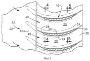
Фиг.1 изображает вид осевого сечения части вентилятора газотурбинного двигателя согласно типичному варианту осуществления настоящего изобретения.1 is an axial sectional view of a part of a fan of a gas turbine engine according to a typical embodiment of the present invention.
Фиг.2 изображает вид в плане соседних лопаток вентилятора, показанных на фиг.1, данный по линии 2-2.FIG. 2 is a plan view of adjacent fan blades shown in FIG. 1, taken along line 2-2.
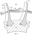
Фиг.3 изображает изометрический вид корневых частей лопаток вентилятора и стенки внутреннего канала для потока в вентиляторе, показанном на фиг.1, данный, в целом, по линии 3-3.Figure 3 depicts an isometric view of the root parts of the fan blades and the walls of the internal channel for the flow in the fan shown in figure 1, given, in General, along the line 3-3.
Фиг.4 изображает вид радиального сечения соседних лопаток вентилятора, показанных на фиг.2, сделанного вблизи их передней кромки по линии 4-4.Figure 4 depicts a view of the radial section of the adjacent fan blades shown in figure 2, made near their leading edge along the line 4-4.
Фиг.5 изображает вид радиального сечения соседних лопаток вентилятора, показанных на фиг.2, сделанного вблизи их задней кромки по линии 5-5.Figure 5 depicts a radial section of the adjacent fan blades shown in figure 2, made near their trailing edge along the line 5-5.
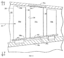
Фиг.6 изображает с частичным осевым сечением вид части многоступенчатого осевого компрессора, расположенного после вентилятора, показанного на фиг.1, соответствующего другому варианту осуществления изобретения.FIG. 6 is a partial axial cross-sectional view of a portion of a multi-stage axial compressor located downstream of the fan of FIG. 1 in accordance with another embodiment of the invention.
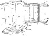
Фиг.7 изображает вид с радиальным сечением соседних частей ступеней ротора и статора компрессора, показанного на фиг.6, данный по линии 7-7.Fig.7 depicts a view with a radial section of the adjacent parts of the stages of the rotor and stator of the compressor shown in Fig.6, given along the line 7-7.
На фиг.1 показана часть турбовентиляторного газотурбинного двигателя 10, который осесимметричен вокруг центральной оси 12. Двигатель включает компрессор низкого давления в форме вентилятора 14, пригодным образом приводимого в действие турбиной низкого давления (не показана). Вентилятор 14 включает ряд лопастей ротора вентилятора или лопаток 16, отступающих радиально наружу от опорного диска 18 ротора и установленных известным способом, например, при помощи замков типа "ласточкин хвост", удерживаемых в соответствующих пазах в форме ласточкина хвоста по периметру диска.Figure 1 shows a part of a turbofan gas turbine engine 10, which is axisymmetric about a central axis 12. The engine includes a low pressure compressor in the form of a fan 14, suitably driven by a low pressure turbine (not shown). The fan 14 includes a number of fan rotor blades or
Лопатки 16, показанные на фиг.1, разнесены по окружности или в боковом направлении друг от друга, как более подробно показано на фиг.2, и образуют между собой соответствующие части канала 20 для потока в вентиляторе, по которому при работе направляется воздух 22. Вращение диска вентилятора и расположенных на нем лопаток сообщает энергию воздуху, который сначала ускоряется и затем замедляется посредством рассеивания для извлечения энергии для сжатия воздуха.The
Воздух, сжатый наружной частью размаха лопаток вентилятора, используется для получения тяги, необходимой для сообщения движения самолету в полете. Воздух, сжатый внутренней частью размаха лопаток, направляется в расположенный дальше по ходу потока компрессор, описанный ниже, который дополнительно сжимает воздух, который затем смешивается с топливом в камере сгорания (не показана) и воспламеняется для генерирования горячих газообразных продуктов сгорания. Энергия извлекается из газообразных продуктов сгорания турбиной высокого давления (не показана) для приведения в действие компрессора, и дополнительная энергия извлекается турбиной низкого давления для приведения в действие вентилятора известным способом.The air compressed by the outer part of the fan blade span is used to obtain the thrust necessary to communicate the movement of the aircraft in flight. Air compressed by the inside of the span of the blades is directed to a compressor located downstream, which is further compressed, which then mixes with the fuel in the combustion chamber (not shown) and ignites to generate hot gaseous products of combustion. Energy is extracted from the gaseous products of combustion by a high pressure turbine (not shown) to drive the compressor, and additional energy is extracted by the low pressure turbine to drive the fan in a known manner.
Как показано на фиг.1 и 2, каждая лопатка 16 включает, в целом, выпуклую сторону 24 разрежения и по окружности противоположную, в целом, вогнутую сторону 26 повышенного давления. Две стороны проходят между разнесенными в осевом направлении передней и задней кромками 28, 30 и по радиальному размаху между радиально наружным концом 32, образующим оконечность лопатки, и радиально противоположным, внутренним концом 34, образующим корневую часть лопатки.As shown in FIGS. 1 and 2, each
Канал 20 для потока в вентиляторе, показанный на фиг.2, ограничен по окружности соответствующими сторонами соседних лопаток вентилятора и ограничен в радиальном направлении, как показано более конкретно на фиг.1. Кольцевой корпус вентилятора или кожух 36 образует радиально наружную границу или стенку, которая по окружности перекрывает все лопатки вентилятора у их наружных оконечностей 32. Множество расположенных между лопатками пластин 38 отнесены радиально наружу от диска 18 и соединены с ним известным способом. Отдельные пластины 38 по окружности соединяют соседние лопатки у их внутренних корневых концов 34. Соответственно, воздушный поток 22 в вентиляторе ограничен при работе соответствующими каналами 20 для потока, образованными по окружности соседними лопатками 16 и в радиальном направлении кожухом 36 вентилятора и пластинами 38.The
Лопатки 16 вентилятора, показанные на фиг.1 и 2, могут иметь любую известную трехмерную конфигурацию для нагнетания воздуха 22 для создания тяги при соответствующей эффективности сжатия и запасе по срыву потока. Отдельные каналы 20 для потока в вентиляторе расходятся в осевом направлении по ходу потока до их выходных концов у задних кромок для рассеивания воздуха 22 и получения его статического давления. Лопатки вентилятора обычно предназначены для работы с околозвуковыми или сверхзвуковыми числами М потока при соответственно высокой скорости вращения ротора при работе. Лопатки, таким образом, при работе подвергаются воздействию скачка уплотнения, при этом между соседними лопатками создаются ударные волны. Вредные эффекты от скачка уплотнения уменьшаются, когда это возможно, выполнением особой конфигурации лопатки вдоль ее размаха.The
Например, каналы 20 для потока в вентиляторе обычно расходятся от входной минимальной площади критического сечения у передних кромок лопаток для нижних частей размаха большинства лопаток. Каналы для потока в области наружной части размаха, заканчивающейся у оконечностей лопаток, обычно сначала сужаются по ходу в осевом направлении до минимальной площади критического сечения, расположенного пригодным образом, и затем увеличиваются по площади до задних кромок лопаток.For example, the
Как показано на фиг.1, кожух 36 вентилятора отнесен от оконечностей 32 лопаток для образования между ними соответствующих небольших радиальных зазоров или просветов, допускающих вращательное движение лопаток внутри неподвижного кожуха 36 без нежелательного трения о него оконечностей. Наружная граница канала для потока, таким образом, неподвижна относительно вращающихся лопаток. Соответственно, пластины 38 лопаток, образующие радиально внутренние границы каналов, прикреплены к диску ротора и вращаются вместе с лопатками без относительного вращательного движения между ними.As shown in figure 1, the fan casing 36 is spaced from the
Размер лопаток, включая их размах от корневой части до оконечности, первоначально задается для получения необходимого значения объема нагнетаемого лопаткой потока, которое обычно выражается в массе на единицу времени. Соответственно, внутренний диаметр кожуха 36 вентилятора и наружный диаметр расположения пластин 38 лопаток относительно центральной оси 12 двигателя также задаются и, таким образом, ограничивают полезную площадь сечения потока соответствующих каналов 20 для потока.The size of the blades, including their span from the root to the tip, is initially set to obtain the required volume of the flow pumped by the blade, which is usually expressed in mass per unit time. Accordingly, the inner diameter of the fan casing 36 and the outer diameter of the
Трехмерные аэродинамические конфигурации лопаток вентилятора могут оптимизироваться с использованием трехмерного компьютерного исследования для достижения максимальной эффективности нагнетания потока и сжатия с пригодным запасом по срыву потока, которые изменяются как функция скорости вращения двигателя от низкой до высокой скорости, требуемой для типичной работы двигателя для энергоснабжения самолета от холостой мощности до крейсерской мощности и до работы с максимальной мощностью.The three-dimensional aerodynamic configurations of the fan blades can be optimized using three-dimensional computer studies to achieve maximum flow and compression efficiency with a suitable stall margin, which varies as a function of the engine speed from low to high speed required for typical engine operation to power the aircraft from idle power to cruising power and to work with maximum power.
Согласно типовому варианту осуществления настоящего изобретения, как показано на фиг.1 и 2, каждая из пластин 38, которые образуют внутреннюю границу канала для потока или стенку, включает ложбину или желоб 40, расположенный вблизи передних кромок 28 лопаток, для локального увеличения там площади сечения потока. Как показано на фиг.2 и 3, каждый желоб 40 проходит в боковом направлении по ширине по окружности между соседними передними кромками 28 и проходит по длине в осевом направлении назад от передних кромок.According to a typical embodiment of the present invention, as shown in FIGS. 1 and 2, each of the
Каждый желоб 40 предпочтительно имеет по существу однообразную ширину по окружности от его начала до конца. Каждый желоб 40 предпочтительно заканчивается в пластине 38 в осевом направлении в точке, расположенной раньше по ходу потока или спереди от задних кромок 30 лопаток. В месте его окончания желоб переходит в выпуклую по окружности площадку 38а, составляющую остальную поверхность пластины.Each
Эта предпочтительная форма желобов 40 дает много преимуществ компрессору, такому как вентилятор низкого давления или компрессор высокого давления, которые ограничены с точки зрения общих размеров геометрическими границами, такими как наружный и внутренний диаметры границ канала для потока. Например, вогнутый радиально внутрь желоб 40 в пластинах 38, показанный на фиг.3, обеспечивает получение локального увеличения площади сечения потока вблизи корневых частей 34 лопаток между передней и задней кромками.This preferred shape of the
Это увеличенное сечение взаимодействует с расширяющимися каналами 20 для потока для локального понижения среднего числа М воздушного потока вблизи передних кромок лопаток, что обеспечивает меньшее рассеивание для достижения требуемого повышения давления между передней и задней кромками лопатки. Поток с локально пониженным числом М соответственно уменьшает сопротивление от поверхностного трения в этом районе для соответственного повышения эффективности сжатия. Для работы с дозвуковой скоростью увеличенное сечение канала для потока у передних кромок лопаток обладает повышенной эффективностью сжатия и дополнительно позволяет модифицировать распределение нагрузки рассеивания по аэродинамическим поверхностям лопатки для дополнительного улучшения характеристик в дополнение к пониженному рассеиванию.This enlarged cross-section interacts with expanding
Для работы со сверхзвуковой скоростью, вызывающей ударные волны, локальное увеличение площади, обеспечиваемое желобами у передних кромок лопаток, дополнительно расширяет или увеличивает входной район канала для потока. Входной район это специальный термин, и он означает район, образованный между передней кромкой одной лопатки и точкой сразу после передней кромки следующей соседней лопатки на ее стороне разрежения, где была выявлена первая захваченная волна Маха. Благодаря локальному расширению входного района в пластинах вблизи передних кромок получен увеличенный расход потока или улучшенное нагнетание вентиляторной ступенью с увеличением эффективности сжатия.To operate at a supersonic speed causing shock waves, the local increase in area provided by the grooves at the leading edges of the blades further expands or increases the inlet region of the flow channel. The entrance region is a special term, and it means the region formed between the leading edge of one blade and the point immediately after the leading edge of the next adjacent blade on its rarefaction side, where the first captured Mach wave was detected. Due to the local expansion of the inlet region in the plates near the leading edges, an increased flow rate or improved discharge by the fan stage with an increase in compression efficiency is obtained.
Локальное расширение входного района и критического сечения канала для потока в этом районе уменьшает эффективную кривизну профиля при работе вентилятора с высокой скоростью. Это, в свою очередь, повышает высокоскоростной расход потока и эффективность на значительные величины, что подтверждено сравнительными анализами одинаковых конструкций лопаток, в разных случаях отличающихся только внесением в конструкцию пластин желобов в противоположность соответствующим не имеющим желобов пластинам.Local expansion of the inlet region and the critical channel section for the flow in this region reduces the effective curvature of the profile when the fan is operating at high speed. This, in turn, increases the high-speed flow rate and efficiency by significant values, which is confirmed by comparative analyzes of the same blade designs, in different cases differing only in the introduction of the gutter plates in the design, as opposed to the corresponding gutter-free plates.
Уже одно применение желобчатых пластин лопаток обеспечивает повышение характеристик, но кроме того, оно также позволяет выполнять дополнительную модификацию распределения нагрузки по лопаткам вблизи их корневых частей, в противном случае невозможную из-за обычных ограничений производительности сжатия, включающих запас по срыву потока. Аэродинамические контуры лопаток, таким образом, могут быть дополнительно оптимизированы в дополнение к применению желобчатых пластин для дальнейшего увеличения производительности по нагнетанию потока вентилятором и эффективности сжатия с одновременным сохранением пригодного запаса по срыву потока. Например, желобчатые пластины эффективны в уменьшении интенсивности скачка уплотнения при работе со сверхзвуковой скоростью, а также уменьшают вторичные поля скоростей потока вблизи корневых частей лопаток.Already one application of the grooved blades of the blades provides an increase in performance, but in addition, it also allows for additional modification of the load distribution among the blades near their root parts, otherwise impossible due to the usual limitations of compression performance, including a margin of stall flow. The aerodynamic contours of the blades can thus be further optimized in addition to the use of grooved plates to further increase the fan flow rate and compression efficiency while maintaining a suitable stall margin. For example, grooved plates are effective in reducing the intensity of the shock wave when operating at supersonic speeds, and also reduce secondary flow velocity fields near the root parts of the blades.
Посредством уменьшения уровней локального рассеивания и интенсивности скачка уплотнения благодаря применению желобчатых пластин потери давления при приближении к пределу потока, накладываемому возможностью запирания кольцевого канала, уменьшаются. В случае с околозвуковым ротором высокоскоростной поток может ограничиваться определенными характеристиками угла атаки на стороне разрежения лопаток вентилятора, двигаясь от передней кромки назад, к первой захваченной волне Маха на стороне разрежения во входном районе или сечении. Желоба увеличивают входной район и в результате больший воздушный поток проходит при тех же определенных характеристиках угла атаки. Кроме того, соответствующее распределение сечения потока, характерное для желобов пластин, увеличивает сходимость кольцевого канала, проходящего через ряд лопаток. В особенности при высоких значениях расхода потока это ведет к уменьшению срыва потока и, следовательно, к улучшению эффективности ротора.By reducing the levels of local dispersion and the intensity of the shock wave due to the use of grooved plates, the pressure loss is reduced when approaching the flow limit imposed by the possibility of locking the annular channel. In the case of a transonic rotor, the high-speed flow can be limited by certain characteristics of the angle of attack on the rarefaction side of the fan blades, moving from the leading edge back to the first captured Mach wave on the rarefaction side in the input region or section. The gutters increase the inlet area and as a result a larger air flow passes with the same defined angle of attack characteristics. In addition, the corresponding distribution of the flow cross section, characteristic of the troughs of the plates, increases the convergence of the annular channel passing through a series of blades. Especially at high flow rates, this leads to a decrease in flow stall and, consequently, to improved rotor efficiency.
Увеличение площади, полученное благодаря снабжению пластин лопаток желобами, достигается без увеличения, как было бы в другом случае, размаха лопаток, которые могут сохранять заданный размер для заданного варианта применения. Увеличенное сечение потока получено без изменения механических и аэромеханических характеристик, связанных с увеличением размаха лопаток, и без увеличения веса, которое требовалось бы для этого в противном случае.The increase in the area obtained by supplying the blade plates with gutters is achieved without increasing, as in another case, the span of the blades, which can maintain a given size for a given application. An increased flow cross section was obtained without changing the mechanical and aeromechanical characteristics associated with an increase in the span of the blades, and without increasing the weight that would otherwise be required for this.
Для получения максимального преимущества отдельные желоба 40, показанные на фиг.1-3, должны начинаться в осевом направлении спереди от передних кромок 28 лопаток или раньше по ходу потока внутри располагаемого пространства в двигателе. Например, вентилятор, показанный на фиг.1, включает конический обтекатель 42, который в осевом направлении примыкает к ряду лопаток вентилятора и пластин 38, с соответствующей щелью или осевым зазором между ними. Каждый желоб 40 предпочтительно включает входную часть 40а, расположенную на наружной поверхности обтекателя 42 и начинающуюся на обтекателе в пригодной точке, расположенной спереди от передних кромок лопаток, и затем продолжается назад, в соответствующие пластины 38 лопаток. Входные части 40а желобов плавно переходят в основные желоба 40 в месте стыка обтекателя и пластин.To obtain maximum advantage, the
В предпочтительном варианте осуществления изобретения, показанном на фиг.2 и 3, каждый желоб 40 предпочтительно имеет по существу единообразную ширину по окружности от его начала на обтекателе 42 до передних кромок 28 лопаток на пластинах и затем сохраняет единообразную ширину между сторонами лопаток по направлению к его окончанию или завершению, предпочтительно расположенному спереди от задних кромок 30 на пластинах. Профиль желобов 40 в осевом направлении предпочтительно соответствует доминирующему направлению линий обтекания потока, движущегося между соседними лопатками, имеющими, в целом, конфигурацию полумесяца.In the preferred embodiment of FIGS. 2 and 3, each
Конфигурация желобов может изменяться, как необходимо для максимизации улучшения их характеристик. Например, между соседними лопатками вентилятора может использоваться один или множество желобов, и круглый контур желобов может изменяться, как необходимо для максимизации характеристик и обеспечения пригодного перехода в стороны лопаток. Контуры площадок пластин могут дополнительно изменяться для дополнения аэродинамических характеристик взаимодействующих желобов в других конфигурациях, как необходимо.The configuration of the gutters can be changed as necessary to maximize the improvement of their characteristics. For example, one or a plurality of troughs may be used between adjacent fan blades, and the round outline of the troughs may be varied as necessary to maximize performance and provide a suitable transition to the sides of the blades. The contours of the plate pads can be further modified to supplement the aerodynamic characteristics of the interacting troughs in other configurations as necessary.
Описанные выше желоба 40 для использования на пластинах лопаток вентилятора могут также использоваться для получения преимуществ соответствующих каналов для потока, также обозначенных номером 20, между лопатками или лопастями ротора компрессора, обозначенными номером 16b на фиг.6 и 7. Подобно лопаткам вентилятора лопатки 16b компрессора отступают радиально наружу от опорного диска ротора в форме кольцевого барабана 18b. Соответствующие каналы 20 для потока в компрессоре образованы по окружности между соседними лопатками компрессора и в радиальном направлении между соответствующим кожухом компрессора или наружной стенкой 36b и радиально внутренними пластинами 38b лопаток. Тогда как пластины 38 лопаток вентилятора, показанные на фиг.1, являются отдельными компонентами, установленными между соседними лопатками вентилятора, пластины 38b лопаток компрессора, показанные на фиг.6 и 7, соединены как единое целое с корневыми частями соответствующих лопаток компрессора и стыкуются друг с другом вблизи середины каждого потока канала для потока.The above-described
Желоба 40 могут выполняться на пластинах 38b лопаток компрессора по существу таким же образом, как и на пластинах лопаток вентилятора, описанных выше. Однако поскольку в ступенях осевого компрессора, показанных на фиг.6, нет обтекателя, желоба в типичном варианте выполнения начинаются сразу за передними кромками самих отдельных пластин 38b по причине ограниченного пространства в осевом направлении, оставляемого расположенными раньше по ходу потока лопатками статора.The
Поскольку лопатки 16b компрессора имеют аэродинамическую конфигурацию, подобную конфигурации больших по размеру лопаток вентилятора, имеющие соответствующие размеры желоба 40 могут подобным образом выполняться на пластинах 38b компрессора. Каждый желоб 40 вновь проходит по окружности по ширине между передними кромками соседних лопаток компрессора и заканчиваются по длине в осевом направлении спереди от задних кромок 30.Since the
В этом варианте осуществления изобретения желоба просто сужаются по ширине между передними и задними кромками в осевом направлении назад. Каждый желоб, таким образом, сужается или уменьшается по ширине вдоль окружности от передних кромок 28 лопаток в осевом направлении в сторону задних кромок 30.In this embodiment, the gutters simply narrow in width between the leading and trailing edges in the axial direction back. Each trough, thus, narrows or decreases in width along the circumference from the leading
Поскольку аэродинамические нагрузки на сторону разрежения и сторону повышенного давления лопатки разные, желоба 40 имеют такую конфигурацию профиля, которая дополняет разность аэродинамических нагрузок. Предпочтительно каждый желоб 40 прилегает к стороне 24 разрежения одной лопатки 16b и отходит от стороны 26 повышенного давления соседней лопатки 16b, образуя канал 20 для потока между ними.Since the aerodynamic loads on the rarefaction side and the high pressure side of the blade are different, the
Как показано на фиг.7, каждый желоб 40 сначала вогнут по окружности радиально внутрь между передними кромками соседних лопаток 16. Поскольку каждый желоб 40 сужается по ширине от передних до задних кромок 28, 30, он следует выпуклому контуру стороны 24 разрежения лопатки, к которой он примыкает, но отходит от стороны 26 повышенного давления соседней лопатки.As shown in Fig. 7, each
Как показано на фиг.7, желоб 40 остается вогнутым по мере его сужения по ширине вдоль окружности и переходит в выпуклую по окружности площадку 38 а пластины, в которой сформирован желоб. За исключением вогнутого желоба 40 все наружные поверхности отдельных пластин 38 лопаток выпуклы по окружности радиально наружу известным образом. Вогнутые желоба 40 изменяют кривизну наружной поверхности пластины на обратную, образуя локально увеличенную площадь сечения потока, тогда как не снабженные желобом части пластин, такие как площадки 38а, остаются выпуклыми по наружному профилю.As shown in FIG. 7, the
Полученный серповидный в осевом направлении профиль отдельных желобов 40 соответствует доминирующим линиям обтекания воздушного потока между соседними лопатками и локально увеличивает площадь сечения потока в соответствующих частях каналов 20 для потока, начинающихся вблизи передних кромок лопаток и заканчивающихся вблизи задних кромок лопаток. Желоба 40, таким образом, следуют в осевом направлении вдоль по существу всего профиля сторон 24 разрежения лопаток, одновременно отходя от сторон 26 повышенного давления лопаток по ходу потока позади их передних кромок. Простой вогнутый желоб дает многие преимущества, описанные выше, для работы с дозвуковой и сверхзвуковой скоростями.The axially sickle-shaped profile of the
На фиг.6 и 7 также показан другой вариант осуществления изобретения, в котором каналы 20 для потока в компрессоре образованы между соседними лопатками статора, обозначенными номером 16с, которые проходят в радиальном направлении между кольцевым наружным поясом или стенкой 36с и радиально внутренним поясом или стенкой 38с. Отдельные лопатки 16с пригодным образом прикреплены их соответствующими наружными и внутренними концами к соответствующим поясам. Пояса в типичном варианте выполнения сформированы в виде дуговых сегментов, совместно формирующих кольца. Внутренний пояс 38с может быть необязательным, и в некоторых вариантах конструкции внутренние концы лопаток просто плоские, без прикрепленных элементов пояса.6 and 7 also show another embodiment of the invention in which the
Как и в предшествующих двух вариантах осуществления изобретения, желоба 40 могут иметь соответствующие размеры для использования по меньшей мере в наружном поясе 36с и, если необходимо, во внутреннем поясе 38с для дополнительного улучшения характеристик лопаток статора. Как и в предшествующих вариантах, желоба могут выполняться в поясах статора для локального увеличения в нем площади сечения потока для улучшения аэродинамических характеристик и эффективности аналогичным образом.As in the previous two embodiments, the
Во всех трех описанных выше вариантах осуществления изобретения соответствующие каналы 20 для потока в компрессоре образованы по кольцу между соседними лопатками 16 вентилятора лопатками 16b компрессора или лопатками 16с статора. Каналы для потока также образованы в радиальном направлении между соответствующими наружной и внутренней стенками в форме кожухов, поясов или пластин. Во всех вариантах осуществления изобретения соответствующие желоба 40 выполнены в стенках, которые неподвижно зафиксированы относительно примыкающих лопаток, которые предназначены для осуществления рассеивания воздушного потока.In all three of the above embodiments, the
Соответствующие желоба могут подобным образом конфигурироваться так, чтобы они имели вогнутый профиль и пригодные ширину и контур вдоль окружности между лопатками и пригодные контуры в осевом направлении между передней и задней кромками. Для оптимизации отдельных контуров соответствующих желобов может использоваться исследование для получения наилучших характеристик каждого из конкретных вариантов, описанных выше. Отдельные желоба, выполненные в соответствующих стенках канала для потока, локально увеличивают площадь сечения потока, при этом стенки в остальном имеют обычные конфигурацию и размеры.Corresponding gutters can likewise be configured so that they have a concave profile and a suitable width and contour along the circumference between the blades and suitable contours in the axial direction between the leading and trailing edges. To optimize the individual contours of the respective gutters, research can be used to obtain the best characteristics of each of the specific options described above. Separate gutters made in the corresponding walls of the flow channel locally increase the cross-sectional area of the flow, while the walls otherwise have the usual configuration and dimensions.
Соответственно, для данной геометрии вентиляторной ступени, роторной ступени компрессора или статорной ступени компрессора желоба могут вводиться в их конструкцию для обеспечения дополнительных преимуществ их характеристик без других изменений геометрии соответствующих ступеней.Accordingly, for a given geometry of the fan stage, the rotor stage of the compressor, or the stator stage of the compressor, the troughs can be introduced into their design to provide additional advantages of their characteristics without other changes in the geometry of the corresponding stages.
Хотя здесь было описано то, что рассматривается как предпочтительные и типовые варианты осуществления настоящего изобретения, для специалиста в данной области техники по данному описанию будут очевидны другие модификации изобретения, и, таким образом, необходимо, чтобы все такие модификации были зафиксированы в прилагаемой формуле изобретения, как соответствующие сущности и объему изобретения.Although what has been described here as being considered as preferred and exemplary embodiments of the present invention, other modifications of the invention will be apparent to those skilled in the art from this description, and thus it is necessary that all such modifications be embodied in the appended claims, as appropriate to the essence and scope of the invention.
Соответственно, то, что необходимо защитить патентной грамотой США, является изобретением, описанным в нижеследующей формуле изобретения с приведением его отличительных признаков.Accordingly, what is required to be protected by a US patent is the invention described in the following claims, with its distinguishing features.
Claims (24)
Applications Claiming Priority (2)
| Application Number | Priority Date | Filing Date | Title |
|---|---|---|---|
| US09/507,408 US6561761B1 (en) | 2000-02-18 | 2000-02-18 | Fluted compressor flowpath |
| US09/507,408 | 2000-02-18 |
Publications (2)
| Publication Number | Publication Date |
|---|---|
| RU2001104477A RU2001104477A (en) | 2003-01-20 |
| RU2232922C2 true RU2232922C2 (en) | 2004-07-20 |
Family
ID=24018530
Family Applications (1)
| Application Number | Title | Priority Date | Filing Date |
|---|---|---|---|
| RU2001104477/06A RU2232922C2 (en) | 2000-02-18 | 2001-02-16 | Grooved channel for gas flow in compressor (versions) |
Country Status (7)
| Country | Link |
|---|---|
| US (1) | US6561761B1 (en) |
| EP (1) | EP1126132A3 (en) |
| JP (1) | JP4974096B2 (en) |
| BR (1) | BR0100603B1 (en) |
| CA (1) | CA2333843C (en) |
| PL (1) | PL200265B1 (en) |
| RU (1) | RU2232922C2 (en) |
Cited By (11)
| Publication number | Priority date | Publication date | Assignee | Title |
|---|---|---|---|---|
| RU2476678C2 (en) * | 2008-01-30 | 2013-02-27 | Снекма | Turbojet compressor |
| RU2488001C2 (en) * | 2008-02-28 | 2013-07-20 | Снекма | Turbo machine impeller vane and turbo machine |
| RU2496986C2 (en) * | 2008-02-28 | 2013-10-27 | Снекма | Blade for turbomachine impeller, area of turbomachine nozzle block, impeller and turbomachine |
| RU2498081C2 (en) * | 2008-02-28 | 2013-11-10 | Снекма | Blade with asymmetrical platform, rotor blade wheel, turbomachine and turbomachine nozzle diaphragm section |
| RU2556151C2 (en) * | 2009-10-02 | 2015-07-10 | Снекма | Turbomachine compressor rotor, turbomachine compressor and turbomachine |
| RU2583190C2 (en) * | 2010-05-26 | 2016-05-10 | Снекма | Vortex generators at inlet of compressor blade system |
| RU2655085C2 (en) * | 2012-07-27 | 2018-05-23 | Снекма | Part of changing the contour of aerodynamic path |
| RU2675980C2 (en) * | 2013-10-11 | 2018-12-25 | Сафран Эркрафт Энджинз | Turbomachine component with non-axisymmetric surface |
| RU2711204C2 (en) * | 2015-02-09 | 2020-01-15 | Сафран Эркрафт Энджинз | Gas turbine engine airflow straightening assembly and gas turbine engine comprising such unit |
| RU2715131C2 (en) * | 2015-02-09 | 2020-02-25 | Сафран Эркрафт Энджинз | Gas turbine engine air flow straightening unit with improved aerodynamic characteristics |
| RU2753104C2 (en) * | 2016-12-23 | 2021-08-11 | Циль-Абегг СЕ | Fan module, and system for one or several fan units in flow duct |
Families Citing this family (110)
| Publication number | Priority date | Publication date | Assignee | Title |
|---|---|---|---|---|
| JP2001271602A (en) * | 2000-03-27 | 2001-10-05 | Honda Motor Co Ltd | Gas turbine engine |
| US6524070B1 (en) * | 2000-08-21 | 2003-02-25 | General Electric Company | Method and apparatus for reducing rotor assembly circumferential rim stress |
| US6669445B2 (en) * | 2002-03-07 | 2003-12-30 | United Technologies Corporation | Endwall shape for use in turbomachinery |
| JP2005155613A (en) * | 2003-10-31 | 2005-06-16 | Hitachi Ltd | Gas turbine and its manufacturing method |
| US7441410B2 (en) | 2003-10-31 | 2008-10-28 | Hitachi, Ltd. | Gas turbine and manufacturing process of gas turbine |
| JP4913326B2 (en) * | 2004-01-05 | 2012-04-11 | 株式会社Ihi | Seal structure and turbine nozzle |
| CA2569026C (en) * | 2004-09-24 | 2009-10-20 | Ishikawajima-Harima Heavy Industries Co., Ltd. | Wall configuration of axial-flow machine, and gas turbine engine |
| US7217096B2 (en) * | 2004-12-13 | 2007-05-15 | General Electric Company | Fillet energized turbine stage |
| US7134842B2 (en) * | 2004-12-24 | 2006-11-14 | General Electric Company | Scalloped surface turbine stage |
| US7249933B2 (en) * | 2005-01-10 | 2007-07-31 | General Electric Company | Funnel fillet turbine stage |
| WO2006080055A1 (en) | 2005-01-26 | 2006-08-03 | Ishikawajima-Harima Heavy Industries Co., Ltd. | Turbofan engine |
| US7476086B2 (en) * | 2005-04-07 | 2009-01-13 | General Electric Company | Tip cambered swept blade |
| US7374403B2 (en) | 2005-04-07 | 2008-05-20 | General Electric Company | Low solidity turbofan |
| US7220100B2 (en) * | 2005-04-14 | 2007-05-22 | General Electric Company | Crescentic ramp turbine stage |
| US7484935B2 (en) * | 2005-06-02 | 2009-02-03 | Honeywell International Inc. | Turbine rotor hub contour |
| US20070031260A1 (en) * | 2005-08-03 | 2007-02-08 | Dube Bryan P | Turbine airfoil platform platypus for low buttress stress |
| GB0518628D0 (en) * | 2005-09-13 | 2005-10-19 | Rolls Royce Plc | Axial compressor blading |
| US7465155B2 (en) * | 2006-02-27 | 2008-12-16 | Honeywell International Inc. | Non-axisymmetric end wall contouring for a turbomachine blade row |
| JP4616781B2 (en) * | 2006-03-16 | 2011-01-19 | 三菱重工業株式会社 | Turbine cascade endwall |
| US7874794B2 (en) * | 2006-03-21 | 2011-01-25 | General Electric Company | Blade row for a rotary machine and method of fabricating same |
| US8500399B2 (en) * | 2006-04-25 | 2013-08-06 | Rolls-Royce Corporation | Method and apparatus for enhancing compressor performance |
| US8366399B2 (en) * | 2006-05-02 | 2013-02-05 | United Technologies Corporation | Blade or vane with a laterally enlarged base |
| US7887297B2 (en) * | 2006-05-02 | 2011-02-15 | United Technologies Corporation | Airfoil array with an endwall protrusion and components of the array |
| US8511978B2 (en) * | 2006-05-02 | 2013-08-20 | United Technologies Corporation | Airfoil array with an endwall depression and components of the array |
| US7721526B2 (en) | 2006-06-28 | 2010-05-25 | Ishikawajima-Harima Heavy Industries Co., Ltd. | Turbofan engine |
| JP4911344B2 (en) | 2006-07-04 | 2012-04-04 | 株式会社Ihi | Turbofan engine |
| FR2907519B1 (en) * | 2006-10-20 | 2011-12-16 | Snecma | FLOOR PLATFORM FLOOR |
| US8413709B2 (en) * | 2006-12-06 | 2013-04-09 | General Electric Company | Composite core die, methods of manufacture thereof and articles manufactured therefrom |
| US7938168B2 (en) * | 2006-12-06 | 2011-05-10 | General Electric Company | Ceramic cores, methods of manufacture thereof and articles manufactured from the same |
| US20080135721A1 (en) * | 2006-12-06 | 2008-06-12 | General Electric Company | Casting compositions for manufacturing metal casting and methods of manufacturing thereof |
| US7624787B2 (en) * | 2006-12-06 | 2009-12-01 | General Electric Company | Disposable insert, and use thereof in a method for manufacturing an airfoil |
| US7487819B2 (en) * | 2006-12-11 | 2009-02-10 | General Electric Company | Disposable thin wall core die, methods of manufacture thereof and articles manufactured therefrom |
| US8884182B2 (en) | 2006-12-11 | 2014-11-11 | General Electric Company | Method of modifying the end wall contour in a turbine using laser consolidation and the turbines derived therefrom |
| GB0704426D0 (en) * | 2007-03-08 | 2007-04-18 | Rolls Royce Plc | Aerofoil members for a turbomachine |
| JP5283855B2 (en) * | 2007-03-29 | 2013-09-04 | 株式会社Ihi | Turbomachine wall and turbomachine |
| DE102007020025A1 (en) | 2007-04-27 | 2008-10-30 | Honda Motor Co., Ltd. | Shape of a gas channel in an axial flow gas turbine engine |
| US8313291B2 (en) * | 2007-12-19 | 2012-11-20 | Nuovo Pignone, S.P.A. | Turbine inlet guide vane with scalloped platform and related method |
| DE102008021053A1 (en) * | 2008-04-26 | 2009-10-29 | Mtu Aero Engines Gmbh | Reformed flow path of an axial flow machine to reduce secondary flow |
| DE102008031789A1 (en) * | 2008-07-04 | 2010-01-07 | Deutsches Zentrum für Luft- und Raumfahrt e.V. | Method and device for influencing secondary flows in a turbomachine |
| DE102008060424A1 (en) | 2008-12-04 | 2010-06-10 | Rolls-Royce Deutschland Ltd & Co Kg | Turbomachine with sidewall boundary layer barrier |
| US8647067B2 (en) * | 2008-12-09 | 2014-02-11 | General Electric Company | Banked platform turbine blade |
| US8459956B2 (en) * | 2008-12-24 | 2013-06-11 | General Electric Company | Curved platform turbine blade |
| US8231353B2 (en) * | 2008-12-31 | 2012-07-31 | General Electric Company | Methods and apparatus relating to improved turbine blade platform contours |
| US8105037B2 (en) * | 2009-04-06 | 2012-01-31 | United Technologies Corporation | Endwall with leading-edge hump |
| JP5398405B2 (en) * | 2009-07-30 | 2014-01-29 | 三菱重工業株式会社 | Channel structure and gas turbine exhaust diffuser |
| US8439643B2 (en) * | 2009-08-20 | 2013-05-14 | General Electric Company | Biformal platform turbine blade |
| US8403645B2 (en) | 2009-09-16 | 2013-03-26 | United Technologies Corporation | Turbofan flow path trenches |
| DE102009052142B3 (en) * | 2009-11-06 | 2011-07-14 | MTU Aero Engines GmbH, 80995 | axial compressor |
| US20110158808A1 (en) * | 2009-12-29 | 2011-06-30 | Hamilton Sundstrand Corporation | Method for propeller blade root flow control by airflow through spinner |
| US8727716B2 (en) * | 2010-08-31 | 2014-05-20 | General Electric Company | Turbine nozzle with contoured band |
| KR101509364B1 (en) * | 2010-12-24 | 2015-04-07 | 미츠비시 히타치 파워 시스템즈 가부시키가이샤 | Flow path structure and gas turbine exhaust diffuser |
| DE102011006275A1 (en) * | 2011-03-28 | 2012-10-04 | Rolls-Royce Deutschland Ltd & Co Kg | Stator of an axial compressor stage of a turbomachine |
| DE102011006273A1 (en) | 2011-03-28 | 2012-10-04 | Rolls-Royce Deutschland Ltd & Co Kg | Rotor of an axial compressor stage of a turbomachine |
| CH704825A1 (en) * | 2011-03-31 | 2012-10-15 | Alstom Technology Ltd | Turbomachinery rotor. |
| US8926267B2 (en) | 2011-04-12 | 2015-01-06 | Siemens Energy, Inc. | Ambient air cooling arrangement having a pre-swirler for gas turbine engine blade cooling |
| DE102011007767A1 (en) | 2011-04-20 | 2012-10-25 | Rolls-Royce Deutschland Ltd & Co Kg | flow machine |
| US8777576B2 (en) * | 2011-08-22 | 2014-07-15 | General Electric Company | Metallic fan blade platform |
| US9255480B2 (en) | 2011-10-28 | 2016-02-09 | General Electric Company | Turbine of a turbomachine |
| US8967959B2 (en) | 2011-10-28 | 2015-03-03 | General Electric Company | Turbine of a turbomachine |
| US9051843B2 (en) | 2011-10-28 | 2015-06-09 | General Electric Company | Turbomachine blade including a squeeler pocket |
| US8992179B2 (en) | 2011-10-28 | 2015-03-31 | General Electric Company | Turbine of a turbomachine |
| US8807930B2 (en) * | 2011-11-01 | 2014-08-19 | United Technologies Corporation | Non axis-symmetric stator vane endwall contour |
| ES2581753T3 (en) * | 2012-03-15 | 2016-09-07 | Mtu Aero Engines Gmbh | Blade crown segment with annular space delimitation surface with a wavy height profile as well as a procedure for manufacturing it |
| BR112014026360A2 (en) | 2012-04-23 | 2017-06-27 | Gen Electric | turbine airfoil and turbine blade |
| US9267386B2 (en) | 2012-06-29 | 2016-02-23 | United Technologies Corporation | Fairing assembly |
| EP2885506B8 (en) | 2012-08-17 | 2021-03-31 | Raytheon Technologies Corporation | Contoured flowpath surface |
| US9212558B2 (en) * | 2012-09-28 | 2015-12-15 | United Technologies Corporation | Endwall contouring |
| US20140154068A1 (en) * | 2012-09-28 | 2014-06-05 | United Technologies Corporation | Endwall Controuring |
| US9598967B2 (en) * | 2012-12-18 | 2017-03-21 | United Technologies Corporation | Airfoil member and composite platform having contoured endwall |
| ES2535096T3 (en) * | 2012-12-19 | 2015-05-05 | MTU Aero Engines AG | Blade of blade and turbomachine |
| EP2938829B1 (en) | 2012-12-28 | 2019-10-09 | United Technologies Corporation | Platform with curved edges adjacent suction side of airfoil |
| US9297257B2 (en) * | 2013-01-31 | 2016-03-29 | General Electric Company | Spinner assembly with removable fan blade leading edge fairings |
| US10302100B2 (en) | 2013-02-21 | 2019-05-28 | United Technologies Corporation | Gas turbine engine having a mistuned stage |
| WO2014163673A2 (en) | 2013-03-11 | 2014-10-09 | Bronwyn Power | Gas turbine engine flow path geometry |
| US9879540B2 (en) | 2013-03-12 | 2018-01-30 | Pratt & Whitney Canada Corp. | Compressor stator with contoured endwall |
| EP2971576B1 (en) | 2013-03-15 | 2020-06-24 | United Technologies Corporation | Fan exit guide vane platform contouring |
| SG11201508706RA (en) | 2013-06-10 | 2015-12-30 | United Technologies Corp | Turbine vane with non-uniform wall thickness |
| EP2835499B1 (en) * | 2013-08-06 | 2019-10-09 | MTU Aero Engines GmbH | Blade row and corresponding flow machine |
| US10415505B2 (en) | 2013-08-12 | 2019-09-17 | United Technologies Corporation | Non-axisymmetric fan flow path |
| US10378360B2 (en) * | 2013-09-17 | 2019-08-13 | United Technologies Corporation | Fan root endwall contouring |
| US9388704B2 (en) * | 2013-11-13 | 2016-07-12 | Siemens Energy, Inc. | Vane array with one or more non-integral platforms |
| US9644497B2 (en) | 2013-11-22 | 2017-05-09 | Siemens Energy, Inc. | Industrial gas turbine exhaust system with splined profile tail cone |
| US9598981B2 (en) | 2013-11-22 | 2017-03-21 | Siemens Energy, Inc. | Industrial gas turbine exhaust system diffuser inlet lip |
| US9540956B2 (en) | 2013-11-22 | 2017-01-10 | Siemens Energy, Inc. | Industrial gas turbine exhaust system with modular struts and collars |
| US9512740B2 (en) * | 2013-11-22 | 2016-12-06 | Siemens Energy, Inc. | Industrial gas turbine exhaust system with area ruled exhaust path |
| FR3015552B1 (en) | 2013-12-19 | 2018-12-07 | Safran Aircraft Engines | TURBOMACHINE PIECE WITH NON-AXISYMETRIC SURFACE |
| WO2015195112A1 (en) | 2014-06-18 | 2015-12-23 | Siemens Energy, Inc. | End wall configuration for gas turbine engine |
| JP2016040463A (en) * | 2014-08-13 | 2016-03-24 | 株式会社Ihi | Axial flow type turbo machine |
| DE102014225689A1 (en) * | 2014-12-12 | 2016-07-14 | MTU Aero Engines AG | Turbomachine with annulus extension and bucket |
| US9470093B2 (en) * | 2015-03-18 | 2016-10-18 | United Technologies Corporation | Turbofan arrangement with blade channel variations |
| PL412269A1 (en) | 2015-05-11 | 2016-11-21 | General Electric Company | Submerged inlet of flow channel between a rotor vane and a guide vane for the gas turbine with open fan |
| GB2545711B (en) * | 2015-12-23 | 2018-06-06 | Rolls Royce Plc | Gas turbine engine vane splitter |
| US10240462B2 (en) | 2016-01-29 | 2019-03-26 | General Electric Company | End wall contour for an axial flow turbine stage |
| US20170314509A1 (en) * | 2016-04-27 | 2017-11-02 | General Electric Company | Turbofan assembly and method of assembling |
| US10458426B2 (en) | 2016-09-15 | 2019-10-29 | General Electric Company | Aircraft fan with low part-span solidity |
| US10590781B2 (en) * | 2016-12-21 | 2020-03-17 | General Electric Company | Turbine engine assembly with a component having a leading edge trough |
| ES2819128T3 (en) | 2017-03-03 | 2021-04-15 | MTU Aero Engines AG | Contouring of a pallet from a pallet rack |
| US20180306041A1 (en) * | 2017-04-25 | 2018-10-25 | General Electric Company | Multiple turbine vane frame |
| ES2750815T3 (en) * | 2017-07-14 | 2020-03-27 | MTU Aero Engines AG | Profiled wing grille for turbomachines |
| JP6953322B2 (en) * | 2018-02-01 | 2021-10-27 | 本田技研工業株式会社 | How to determine the shape of the fan blade |
| FR3079008B1 (en) * | 2018-03-19 | 2020-02-28 | Safran Aircraft Engines | FLEXIBLE MONOBLOCK BLADE DISC IN THE LOWER PART OF THE BLADES |
| US10890072B2 (en) * | 2018-04-05 | 2021-01-12 | Raytheon Technologies Corporation | Endwall contour |
| FR3082229B1 (en) * | 2018-06-08 | 2020-07-03 | Safran Aircraft Engines | TURBOMACHINE WITH A PARTIAL COMPRESSION VANE |
| CN111435399B (en) | 2018-12-25 | 2023-05-23 | 中国航发商用航空发动机有限责任公司 | Modeling method of fan assembly |
| US20200232330A1 (en) * | 2019-01-18 | 2020-07-23 | United Technologies Corporation | Fan blades with recessed surfaces |
| JP7130575B2 (en) * | 2019-02-28 | 2022-09-05 | 三菱重工業株式会社 | axial turbine |
| FR3098244B1 (en) * | 2019-07-04 | 2021-09-10 | Safran Aircraft Engines | TURBOMACHINE BLADE |
| BE1027709B1 (en) * | 2019-10-25 | 2021-05-27 | Safran Aero Boosters Sa | TURBOMACHINE COMPRESSOR STAGE |
| CN113606187B (en) * | 2021-09-13 | 2023-05-16 | 安徽环茨智能科技有限公司 | Grain type blade of ternary impeller of high-speed centrifugal fan |
| DE102022117268A1 (en) * | 2022-07-12 | 2024-01-18 | MTU Aero Engines AG | Rotor blade and rotor blade arrangement for a turbomachine |
Family Cites Families (20)
| Publication number | Priority date | Publication date | Assignee | Title |
|---|---|---|---|---|
| CH229266A (en) * | 1942-03-26 | 1943-10-15 | Sulzer Ag | Turbomachine, the blade surfaces of which merge into the base surface with a rounding at the blade root. |
| US3316714A (en) * | 1963-06-20 | 1967-05-02 | Rolls Royce | Gas turbine engine combustion equipment |
| US3481531A (en) * | 1968-03-07 | 1969-12-02 | United Aircraft Canada | Impeller boundary layer control device |
| FR1602965A (en) | 1968-08-16 | 1971-03-01 | ||
| US4194869A (en) * | 1978-06-29 | 1980-03-25 | United Technologies Corporation | Stator vane cluster |
| US4804311A (en) * | 1981-12-14 | 1989-02-14 | United Technologies Corporation | Transverse directional solidification of metal single crystal articles |
| US5167489A (en) | 1991-04-15 | 1992-12-01 | General Electric Company | Forward swept rotor blade |
| JPH06257597A (en) * | 1993-03-02 | 1994-09-13 | Jisedai Koukuuki Kiban Gijutsu Kenkyusho:Kk | Cascade structure of axial flow compressor |
| US5275531A (en) | 1993-04-30 | 1994-01-04 | Teleflex, Incorporated | Area ruled fan blade ends for turbofan jet engine |
| US5397215A (en) | 1993-06-14 | 1995-03-14 | United Technologies Corporation | Flow directing assembly for the compression section of a rotary machine |
| JPH07247996A (en) * | 1994-03-11 | 1995-09-26 | Ishikawajima Harima Heavy Ind Co Ltd | Passage form of compressor |
| US5642985A (en) * | 1995-11-17 | 1997-07-01 | United Technologies Corporation | Swept turbomachinery blade |
| GB9607316D0 (en) | 1996-04-09 | 1996-06-12 | Rolls Royce Plc | Swept fan blade |
| US5735673A (en) | 1996-12-04 | 1998-04-07 | United Technologies Corporation | Turbine engine rotor blade pair |
| DE19650656C1 (en) * | 1996-12-06 | 1998-06-10 | Mtu Muenchen Gmbh | Turbo machine with transonic compressor stage |
| DE59806445D1 (en) | 1997-04-01 | 2003-01-09 | Siemens Ag | SURFACE STRUCTURE FOR THE WALL OF A FLOW CHANNEL OR A TURBINE BLADE |
| US5820338A (en) * | 1997-04-24 | 1998-10-13 | United Technologies Corporation | Fan blade interplatform seal |
| US5947688A (en) * | 1997-12-22 | 1999-09-07 | General Electric Company | Frequency tuned hybrid blade |
| EP0943784A1 (en) * | 1998-03-19 | 1999-09-22 | Asea Brown Boveri AG | Contoured channel for an axial turbomachine |
| JP2000274202A (en) * | 1999-03-23 | 2000-10-03 | Toshiba Corp | Fluid machinery |
-
2000
- 2000-02-18 US US09/507,408 patent/US6561761B1/en not_active Expired - Lifetime
-
2001
- 2001-02-01 CA CA002333843A patent/CA2333843C/en not_active Expired - Fee Related
- 2001-02-14 PL PL345839A patent/PL200265B1/en unknown
- 2001-02-16 EP EP01301359A patent/EP1126132A3/en not_active Withdrawn
- 2001-02-16 RU RU2001104477/06A patent/RU2232922C2/en not_active IP Right Cessation
- 2001-02-16 JP JP2001039367A patent/JP4974096B2/en not_active Expired - Fee Related
- 2001-02-16 BR BRPI0100603-7A patent/BR0100603B1/en not_active IP Right Cessation
Cited By (11)
| Publication number | Priority date | Publication date | Assignee | Title |
|---|---|---|---|---|
| RU2476678C2 (en) * | 2008-01-30 | 2013-02-27 | Снекма | Turbojet compressor |
| RU2488001C2 (en) * | 2008-02-28 | 2013-07-20 | Снекма | Turbo machine impeller vane and turbo machine |
| RU2496986C2 (en) * | 2008-02-28 | 2013-10-27 | Снекма | Blade for turbomachine impeller, area of turbomachine nozzle block, impeller and turbomachine |
| RU2498081C2 (en) * | 2008-02-28 | 2013-11-10 | Снекма | Blade with asymmetrical platform, rotor blade wheel, turbomachine and turbomachine nozzle diaphragm section |
| RU2556151C2 (en) * | 2009-10-02 | 2015-07-10 | Снекма | Turbomachine compressor rotor, turbomachine compressor and turbomachine |
| RU2583190C2 (en) * | 2010-05-26 | 2016-05-10 | Снекма | Vortex generators at inlet of compressor blade system |
| RU2655085C2 (en) * | 2012-07-27 | 2018-05-23 | Снекма | Part of changing the contour of aerodynamic path |
| RU2675980C2 (en) * | 2013-10-11 | 2018-12-25 | Сафран Эркрафт Энджинз | Turbomachine component with non-axisymmetric surface |
| RU2711204C2 (en) * | 2015-02-09 | 2020-01-15 | Сафран Эркрафт Энджинз | Gas turbine engine airflow straightening assembly and gas turbine engine comprising such unit |
| RU2715131C2 (en) * | 2015-02-09 | 2020-02-25 | Сафран Эркрафт Энджинз | Gas turbine engine air flow straightening unit with improved aerodynamic characteristics |
| RU2753104C2 (en) * | 2016-12-23 | 2021-08-11 | Циль-Абегг СЕ | Fan module, and system for one or several fan units in flow duct |
Also Published As
| Publication number | Publication date |
|---|---|
| CA2333843A1 (en) | 2001-08-18 |
| EP1126132A3 (en) | 2003-05-02 |
| US6561761B1 (en) | 2003-05-13 |
| BR0100603B1 (en) | 2010-02-09 |
| BR0100603A (en) | 2001-10-09 |
| JP4974096B2 (en) | 2012-07-11 |
| CA2333843C (en) | 2009-09-15 |
| PL345839A1 (en) | 2001-08-27 |
| EP1126132A2 (en) | 2001-08-22 |
| JP2001271792A (en) | 2001-10-05 |
| PL200265B1 (en) | 2008-12-31 |
Similar Documents
| Publication | Publication Date | Title |
|---|---|---|
| RU2232922C2 (en) | Grooved channel for gas flow in compressor (versions) | |
| EP1731733B1 (en) | Integrated counterrotating turbofan | |
| EP1731716B1 (en) | Forward tilted turbine nozzle | |
| EP1731734B1 (en) | Counterrotating turbofan engine | |
| US5988980A (en) | Blade assembly with splitter shroud | |
| EP2689108B1 (en) | Compressor airfoil with tip dihedral | |
| US5480284A (en) | Self bleeding rotor blade | |
| RU2433290C2 (en) | Unit of fan on blade, and also turbofan gas turbine engine | |
| EP1260673B1 (en) | Turbine cooling circuit | |
| EP2778427B1 (en) | Compressor bleed self-recirculating system | |
| EP3199822B1 (en) | Impeller shroud supports having mid-impeller bleed flow passages | |
| EP3361053B1 (en) | Grooved shroud casing treatment for high pressure compressor in a turbine engine | |
| EP1756409B1 (en) | Shockwave-induced boundary layer bleed for transonic gas turbine | |
| EP2520763B1 (en) | Impeller | |
| US20080145216A1 (en) | Ovate band turbine stage | |
| EP2775119B1 (en) | Compressor shroud reverse bleed holes | |
| US11719168B2 (en) | Compressor apparatus with bleed slot and supplemental flange | |
| US20180313364A1 (en) | Compressor apparatus with bleed slot including turning vanes | |
| US20180195528A1 (en) | Fluid diodes with ridges to control boundary layer in axial compressor stator vane | |
| US9970452B2 (en) | Forward-swept impellers and gas turbine engines employing the same | |
| CN116457560A (en) | Aviation propulsion system with improved propulsion efficiency |
Legal Events
| Date | Code | Title | Description |
|---|---|---|---|
| MM4A | The patent is invalid due to non-payment of fees |
Effective date: 20170217 |