RU2232477C2 - Method for signaling among medium access control entities in burst data transfer system - Google Patents
Method for signaling among medium access control entities in burst data transfer system Download PDFInfo
- Publication number
- RU2232477C2 RU2232477C2 RU2002122736A RU2002122736A RU2232477C2 RU 2232477 C2 RU2232477 C2 RU 2232477C2 RU 2002122736 A RU2002122736 A RU 2002122736A RU 2002122736 A RU2002122736 A RU 2002122736A RU 2232477 C2 RU2232477 C2 RU 2232477C2
- Authority
- RU
- Russia
- Prior art keywords
- signaling
- uds
- message
- mac
- sun
- Prior art date
Links
Images

Classifications
-
- H—ELECTRICITY
- H04—ELECTRIC COMMUNICATION TECHNIQUE
- H04L—TRANSMISSION OF DIGITAL INFORMATION, e.g. TELEGRAPHIC COMMUNICATION
- H04L63/00—Network architectures or network communication protocols for network security
- H04L63/18—Network architectures or network communication protocols for network security using different networks or channels, e.g. using out of band channels
-
- H—ELECTRICITY
- H04—ELECTRIC COMMUNICATION TECHNIQUE
- H04L—TRANSMISSION OF DIGITAL INFORMATION, e.g. TELEGRAPHIC COMMUNICATION
- H04L1/00—Arrangements for detecting or preventing errors in the information received
- H04L1/12—Arrangements for detecting or preventing errors in the information received by using return channel
- H04L1/16—Arrangements for detecting or preventing errors in the information received by using return channel in which the return channel carries supervisory signals, e.g. repetition request signals
- H04L1/1607—Details of the supervisory signal
- H04L1/1671—Details of the supervisory signal the supervisory signal being transmitted together with control information
-
- H—ELECTRICITY
- H04—ELECTRIC COMMUNICATION TECHNIQUE
- H04L—TRANSMISSION OF DIGITAL INFORMATION, e.g. TELEGRAPHIC COMMUNICATION
- H04L51/00—User-to-user messaging in packet-switching networks, transmitted according to store-and-forward or real-time protocols, e.g. e-mail
- H04L51/21—Monitoring or handling of messages
-
- H—ELECTRICITY
- H04—ELECTRIC COMMUNICATION TECHNIQUE
- H04W—WIRELESS COMMUNICATION NETWORKS
- H04W52/00—Power management, e.g. TPC [Transmission Power Control], power saving or power classes
- H04W52/04—TPC
- H04W52/18—TPC being performed according to specific parameters
- H04W52/28—TPC being performed according to specific parameters using user profile, e.g. mobile speed, priority or network state, e.g. standby, idle or non transmission
- H04W52/286—TPC being performed according to specific parameters using user profile, e.g. mobile speed, priority or network state, e.g. standby, idle or non transmission during data packet transmission, e.g. high speed packet access [HSPA]
-
- H—ELECTRICITY
- H04—ELECTRIC COMMUNICATION TECHNIQUE
- H04L—TRANSMISSION OF DIGITAL INFORMATION, e.g. TELEGRAPHIC COMMUNICATION
- H04L1/00—Arrangements for detecting or preventing errors in the information received
- H04L1/12—Arrangements for detecting or preventing errors in the information received by using return channel
- H04L1/16—Arrangements for detecting or preventing errors in the information received by using return channel in which the return channel carries supervisory signals, e.g. repetition request signals
- H04L1/18—Automatic repetition systems, e.g. Van Duuren systems
- H04L1/1803—Stop-and-wait protocols
-
- H—ELECTRICITY
- H04—ELECTRIC COMMUNICATION TECHNIQUE
- H04L—TRANSMISSION OF DIGITAL INFORMATION, e.g. TELEGRAPHIC COMMUNICATION
- H04L1/00—Arrangements for detecting or preventing errors in the information received
- H04L1/12—Arrangements for detecting or preventing errors in the information received by using return channel
- H04L1/16—Arrangements for detecting or preventing errors in the information received by using return channel in which the return channel carries supervisory signals, e.g. repetition request signals
- H04L1/18—Automatic repetition systems, e.g. Van Duuren systems
- H04L1/1812—Hybrid protocols; Hybrid automatic repeat request [HARQ]
-
- H—ELECTRICITY
- H04—ELECTRIC COMMUNICATION TECHNIQUE
- H04L—TRANSMISSION OF DIGITAL INFORMATION, e.g. TELEGRAPHIC COMMUNICATION
- H04L1/00—Arrangements for detecting or preventing errors in the information received
- H04L1/12—Arrangements for detecting or preventing errors in the information received by using return channel
- H04L1/16—Arrangements for detecting or preventing errors in the information received by using return channel in which the return channel carries supervisory signals, e.g. repetition request signals
- H04L1/18—Automatic repetition systems, e.g. Van Duuren systems
- H04L1/1829—Arrangements specially adapted for the receiver end
- H04L1/1832—Details of sliding window management
-
- H—ELECTRICITY
- H04—ELECTRIC COMMUNICATION TECHNIQUE
- H04L—TRANSMISSION OF DIGITAL INFORMATION, e.g. TELEGRAPHIC COMMUNICATION
- H04L1/00—Arrangements for detecting or preventing errors in the information received
- H04L2001/0092—Error control systems characterised by the topology of the transmission link
- H04L2001/0096—Channel splitting in point-to-point links
-
- H—ELECTRICITY
- H04—ELECTRIC COMMUNICATION TECHNIQUE
- H04L—TRANSMISSION OF DIGITAL INFORMATION, e.g. TELEGRAPHIC COMMUNICATION
- H04L1/00—Arrangements for detecting or preventing errors in the information received
- H04L1/12—Arrangements for detecting or preventing errors in the information received by using return channel
- H04L2001/125—Arrangements for preventing errors in the return channel
Landscapes
- Engineering & Computer Science (AREA)
- Computer Networks & Wireless Communication (AREA)
- Signal Processing (AREA)
- Computer Hardware Design (AREA)
- Computer Security & Cryptography (AREA)
- Computing Systems (AREA)
- General Engineering & Computer Science (AREA)
- Mobile Radio Communication Systems (AREA)
- Data Exchanges In Wide-Area Networks (AREA)
- Communication Control (AREA)
Abstract
Description
ПриоритетA priority
Настоящая заявка истребует приоритет согласно заявке на “Способ сигнализации между объектами управления доступом к среде в системе передачи пакетных данных”, которая была подана в Корейское Ведомство по промышленной собственности 24 августа 2001 г., которой присвоен номер 2001-52613 и содержание которой включено в настоящую заявку посредством ссылки.This application claims priority according to the application for “A method of signaling between media access control objects in a packet data transmission system”, which was submitted to the Korean Industrial Property Office on August 24, 2001, which is assigned the number 2001-52613 and the contents of which are included in this application by reference.
Область техникиTechnical field
Настоящее изобретение относится к способу сигнализации между одноранговыми (равноправными) уровнями управления доступом к среде (УДС) для пакетного доступа к высокоскоростной прямой линии связи (ПДВСПЛ) в системе связи множественного доступа с кодовым разделением каналов (МДКР), более конкретно к способу перемежающегося обмена информацией управления между объектами УДС в узле В и пользовательском устройстве (ПУ).The present invention relates to a method for signaling between peer-to-peer (medium) media access control (MAC) layers for packet access to a high speed forward link (PDL) in a code division multiple access (CDMA) communication system, and more particularly, to a method for intermittent information exchange control between the objects of the UDS in the node In and the user device (PU).
Предшествующий уровень техникиState of the art
В общем случае пакетный доступ к высокоскоростной прямой линии связи (ПДВСПЛ) относится к высокоскоростному прямому совместно используемому каналу (ВС-ПСК) для поддержки пакетных передач высокоскоростной прямой линии связи и каналов управления, относящихся к ним, в системе связи МДКР, и к устройству, способу и системе для его использования. В системе связи МДКР, использующей ПДВСПЛ, введены следующие три новых метода для поддержки высокоскоростной пакетной передачи.In general, packet access to a high-speed forward link (PDVSPL) refers to a high-speed direct shared channel (BC-UCS) for supporting packet transmissions of a high-speed forward link and control channels related thereto in a CDMA communication system, and to a device, method and system for its use. In a CDMA communication system using PDCPL, the following three new methods have been introduced to support high-speed packet transmission.
Во-первых, ниже описывается адаптивная модуляция и схема кодирования (АМСК). АМСК адаптивно определяет метод модуляции и метод кодирования в канале данных в соответствии с условием в канале между сотовой ячейкой и пользователем, что позволяет увеличить общую эффективность использования сотовой ячейки. Комбинация метода модуляции и метода кодирования определяется как “Схема кодирования модуляции” (СКМ), причем СКМ имеет уровень от 1 до n. АМСК адаптивно определяет уровень СКМ в соответствии с условиями в канале между пользователем и сотовой ячейкой, тем самым повышая общую эффективность использования.First, adaptive modulation and coding scheme (AMSK) are described below. AMSC adaptively determines the modulation method and the coding method in the data channel in accordance with the condition in the channel between the cell and the user, which allows to increase the overall efficiency of use of the cell. The combination of the modulation method and the coding method is defined as “Modulation Coding Scheme” (SCM), wherein the SCM has a level from 1 to n. AMSC adaptively determines the level of SCM in accordance with the conditions in the channel between the user and the cell, thereby increasing the overall efficiency of use.
Далее описан гибридный запрос автоматической повторной передачи (ГЗАПП), в частности n-канальный гибридный запрос автоматической повторной передачи типа “остановка и ожидание” (ГЗАПП-OO). В обычном запросе автоматической повторной передачи (ЗАПП) осуществляется обмен сигналом подтверждения (АСК) и повторно переданным пакетом между пользовательским устройством (ПУ) и контроллером сети радиосвязи (КСР). Однако в случае ПДВСПЛ обмен подтверждениями и повторно передаваемыми пакетами производится между уровнями УДС ПУ и узла В. Кроме того, N логических каналов формируются для передачи множества пакетов даже в состоянии, когда подтверждение (АСК) не принимается. Более конкретно, в существующих ЗАПП-OO следующий пакет не может быть передан, пока не будет принят сигнал подтверждения (АСК) для предыдущего пакета. Поэтому необходимо ожидать приема сигнала подтверждения АСК, хотя имеется возможность передать пакет. Однако в N-канальной системе ЗАПП-OO множество пакетов могут непрерывно передаваться по N каналам, даже до приема сигнала подтверждения АСК по каналу, тем самым повышая эффективность использования канала. Т.е. если между ПУ и узлом В установлено N логических каналов и эти логические каналы могут быть идентифицированы по их номерам каналов или их времени передачи, то ПУ может определить канал, которому принадлежит пакет, принятый в определенной точке, и переупорядочить принятые пакеты в правильном порядке приема.The following describes a hybrid automatic retransmission request (GZAPP), in particular an n-channel hybrid stop and wait automatic retransmission request (GZAPP-OO). In a regular request for automatic retransmission (ZAPP), an acknowledgment signal (ASK) and a retransmitted packet are exchanged between the user device (PU) and the radio network controller (DAC). However, in the case of PDCPL, acknowledgments and retransmitted packets are exchanged between the UDS levels of the control unit and node B. In addition, N logical channels are formed to transmit multiple packets even in the state when acknowledgment (ACK) is not received. More specifically, in existing ZAPP-OO, the next packet cannot be transmitted until an acknowledgment signal (ACK) for the previous packet is received. Therefore, it is necessary to expect reception of an ACK confirmation signal, although it is possible to transmit a packet. However, in an N-channel ZAPP-OO system, a plurality of packets can be continuously transmitted on N channels, even before receiving an ACK confirmation signal on a channel, thereby increasing channel utilization. Those. if N logical channels are established between the control unit and Node B and these logical channels can be identified by their channel numbers or their transmission time, then the control unit can determine the channel to which the packet received at a certain point belongs and reorder the received packets in the correct receiving order.
И, наконец, описывается быстрый выбор сотовой ячейки (БВС). БВС позволяет ПУ, использующему ПДВСПЛ, в зоне гибкой передачи обслуживания принимать пакеты только от сотовой ячейки с наилучшими условиями канала, тем самым снижая общие взаимные помехи. Если другая сотовая ячейка обнаруживает наилучшие условия в канале, то ПУ принимает пакеты из сотовой ячейки по ВС-ПСК, тем самым минимизируя время прерывания передачи.And finally, a quick cell selection (BVS) is described. BVS allows PUs using PDSPL to receive packets only from the cell with the best channel conditions in the flexible handoff zone, thereby reducing overall mutual interference. If the other cell detects the best conditions in the channel, then the UE receives packets from the cell through the VS-UCS, thereby minimizing the transmission interruption time.
Ниже описан недавно предложенный метод гибридного запроса повторной передачи (ГЗАПП) для услуги пакетного доступа высокоскоростной прямой линии (ПДВСПЛ).The following is a recently proposed Hybrid Retransmission Request (GZAPP) method for a High Speed Forward Direct Link Packet Access (PDPSL) service.
Для ПДВСПЛ было предложено множество методов протоколов N-канального ГЗАПП-ОО, причем эти методы можно классифицировать на следующие три метода в соответствии с информацией управления и их методами передачи данных в обратной/прямой линиях связи. Первый метод представляет собой метод синхронной/синхронной передачи, при котором повторная передача данных по прямой линии синхронизируется с каналом, по которому передавались первоначальные данные, а передача подтверждения/неподтверждения (ACK/NACK) по обратной линии также синхронизируется с каналом ГЗАПП. Второй метод представляет собой метод асинхронной/синхронной передачи, при котором повторная передача по прямой линии связи не ограничена каналом, по которому передавались первоначальные данные, но выполняется попеременно асинхронно по различным каналам. Третий метод представляет собой метод асинхронной/асинхронной передачи, при котором даже передача подтверждения/неподтверждения (ACK/NACK) по прямой линии связи не синхронизирована с каналом, по которому передавались первоначальные данные.A variety of protocol methods for N-channel GZAPP-OO have been proposed for PDVSPL, and these methods can be classified into the following three methods in accordance with control information and their data transmission methods in reverse / forward communication lines. The first method is a synchronous / synchronous transmission method in which the forward data retransmission is synchronized with the channel on which the initial data was transmitted, and the acknowledgment / non-acknowledgment (ACK / NACK) transmission on the return line is also synchronized with the GZAPP channel. The second method is an asynchronous / synchronous transmission method, in which the retransmission on the forward link is not limited to the channel on which the initial data was transmitted, but is performed alternately asynchronously on various channels. The third method is an asynchronous / asynchronous transmission method, in which even confirmation / non-acknowledgment (ACK / NACK) transmission on the forward link is not synchronized with the channel on which the initial data was transmitted.
На фиг.1 представлена синхронная передача узлом В и синхронная/синхронная передача пользовательским устройством (ПУ) в случае услуги ПДВСПЛ. На фиг.1 предполагается, что для передачи используются четыре (N) канала.Figure 1 shows the synchronous transmission by the node In and synchronous / synchronous transmission by the user device (PU) in the case of PDVSPL service. 1, it is assumed that four (N) channels are used for transmission.
Как показано на фиг.1, блок данных 101, принимаемый с верхнего уровня сети (или от узла В; в данном случае термины “сеть” и “узел В” используются в одинаковом смысле), сохраняется в очереди 102. Блок данных 101, сохраненный в очереди 102, выдается в канальное устройство генерации последовательности (или распределитель) 103, где выданный блок данных распределяется по передатчикам 104, 105, 106 и 107, связанным с соответствующими каналами. Передатчики 104, 105, 106 и 107 последовательно передают блоки данных, распределенные канальным распределителем 103, и переданные блоки данных принимаются соответствующими приемниками 111, 113, 115 и 117 через канал данных 108. Блоки данных, принятые в приемниках 111, 113, 115 и 117, подаются на декодеры повторной передачи с первого по четвертый (или декодеры ГЗАПП) 112, 114, 116 и 118 соответственно. Блоки данных анализируются соответствующими декодерами ГЗАПП 112, 114, 116 и 118 и затем передаются на более высокий уровень ПУ.As shown in FIG. 1, a data block 101 received from the top level of the network (or from node B; in this case, the terms “network” and “node B” are used in the same sense) are stored in queue 102. Data block 101, saved in queue 102, it is issued to a channel sequence generating device (or distributor) 103, where the issued data block is distributed to transmitters 104, 105, 106 and 107 associated with the respective channels. The transmitters 104, 105, 106 and 107 sequentially transmit the data blocks allocated by the channel distributor 103, and the transmitted data blocks are received by the respective receivers 111, 113, 115 and 117 through the data channel 108. The data blocks received at the receivers 111, 113, 115 and 117 are supplied to the first to fourth retransmit decoders (or GZAPP decoders) 112, 114, 116 and 118, respectively. The data blocks are analyzed by the respective GZAPP decoders 112, 114, 116 and 118 and then transmitted to a higher level of the control panel.
Когда блоки данных передаются, соответствующая информация сигнализации передается по каналу управления. Информация ACK/NACK для переданных блоков данных передается от ПУ в сеть по каналу обратной связи. На фиг.1 представлена диаграмма, поясняющая данный принцип, но действительная система может иметь отличающуюся структуру. Например, хотя согласно фиг.1 использовано множество передатчиков 104-107 и приемников 111-117, для передачи и приема множества блоков данных на базе временного разделения каналов может использоваться один передатчик и один приемник. Кроме того, хотя канал данных 108 предусмотрен между передающей стороной и приемной стороной, передающая сторона имеет буферную память для N каналов ГЗАПП. Приемная сторона также имеет память для объединения данных для N каналов ГЗАПП и буферную память для сбора последовательностей восстановленных сообщений в установленном количестве и передачи их на более высокий уровень.When data blocks are transmitted, the corresponding signaling information is transmitted on the control channel. ACK / NACK information for the transmitted data blocks is transmitted from the PU to the network via the feedback channel. 1 is a diagram explaining this principle, but the actual system may have a different structure. For example, although according to FIG. 1, a plurality of transmitters 104-107 and receivers 111-117 are used, one transmitter and one receiver may be used to transmit and receive multiple data blocks based on time division of channels. In addition, although a data channel 108 is provided between the transmitting side and the receiving side, the transmitting side has a buffer memory for the N channels GZAPP. The receiving side also has a memory for combining data for the N channels of GZAPP and a buffer memory for collecting sequences of recovered messages in a predetermined number and transferring them to a higher level.
Метод синхронной/синхронной передачи, метод повторной передачи, зависящий от временного соотношения между передачей данных по прямой линии связи и приемом сигналов ACK/NACK для переданных данных, не требует номеров последовательностей. Поэтому в прямой линии связи в канале управления необходима передача флага “новый/продолжение” (Н/П) минимум из 1 бита для различения того, является ли передаваемый блок данных новым передаваемым блоком или повторно передаваемым блоком, и информация ACK/NACK по каналу обратной связи может также передаваться посредством минимум 1 бита. Это объясняется тем, что можно различить данные и ACK/NACK каждого канала за счет синхронной передачи.The synchronous / synchronous transmission method, the retransmission method, which depends on the time relationship between data transmission on the forward link and ACK / NACK signal reception for the transmitted data, does not require sequence numbers. Therefore, in the forward link in the control channel, a “new / continued” (N / A) flag must be transmitted from at least 1 bit to distinguish whether the transmitted data block is a new transmitted block or a retransmitted block, and ACK / NACK information on the reverse channel communications may also be transmitted via a minimum of 1 bit. This is because it is possible to distinguish between data and ACK / NACK of each channel due to synchronous transmission.
Метод асинхронной/синхронной передачи подобен по действию методу синхронной/синхронной передачи. Однако поскольку повторная передача блока данных разрешена даже для каналов иных, чем канал, по которому передавались исходные данные, то для канала управления прямой линии связи необходим еще номер канального процессора, в дополнение к флагу Н/П. В методе асинхронной/синхронной передачи информация ACK/NACK по каналу обратной связи передается минимум с 1 битом, подобно методу синхронной/синхронной передачи.The asynchronous / synchronous transmission method is similar in operation to the synchronous / synchronous transmission method. However, since the retransmission of the data block is allowed even for channels other than the channel on which the original data was transmitted, the channel processor number is also necessary for the forward link control channel, in addition to the N / A flag. In the asynchronous / synchronous transmission method, ACK / NACK information is transmitted with at least 1 bit feedback channel, similar to the synchronous / synchronous transmission method.
В методе асинхронной/асинхронной передачи требуется передача номера канального процессора в дополнение к флагу Н/П и передача информации ACK/NACK по каналу обратной связи с номером последовательности для блока данных прямой линии связи. Этот метод увеличивает нагрузку сигнализации, но имеет менее жесткое ограничение по хронированию передачи и более высокую устойчивость по отношению к возможным ошибкам.The asynchronous / asynchronous transmission method requires the transmission of the channel processor number in addition to the N / A flag and the transmission of ACK / NACK information via the feedback channel with the sequence number for the forward link data block. This method increases the signaling load, but has a less stringent limitation on the timing of transmission and higher stability with respect to possible errors.
Вышеописанное функционирование уровня УДС для ПДВСПЛ с использованием ГЗАПП представляет собой принцип, который не был введен в существующие мобильные системы связи, а операции, связанные с повторной передачей, выполняются на уровне управления линией радиосвязи (УЛР).The above-described operation of the UDS level for PDVSPL using GZAPP is a principle that has not been introduced into existing mobile communication systems, and operations related to retransmission are performed at the radio link control (ULR) level.
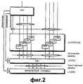
На фиг.2 показана многоуровневая структура протокола в широкополосной системе связи МДКР (Ш-МДКР). В мобильной системе связи контроллер сети радиосвязи (КСР) за исключением сетевого центра (центра коммутации мобильного обслуживания - ЦКМ) содержит уровень управления ресурсами радиосвязи (УРР) для управления каждым элементом сети доступа к радиосвязи, уровень управления линией радиосвязи (УЛР) для обращения с пакетами данных, принятых от верхнего уровня с надлежащим размером, уровень управления доступом к среде (УДС) для распределения/объединения блоков данных с конкретным размером в транспортных каналах и физический уровень (или уровень 1 - L1) 230 для передачи действительных блоков данных по каналу радиосвязи. Уровень УРР принадлежит к уровню 3 (L3), а уровень 210 УЛР принадлежит к уровню 2 (L2).Figure 2 shows the multi-level structure of the Protocol in a broadband communication system mdcr (W-mdcr). In a mobile communication system, the radio network controller (DAC), with the exception of the network center (mobile service switching center - MSC), contains a radio resource management level (RRM) for controlling each element of the radio access network, a radio link control level (ULR) for handling packets data received from the upper layer with the appropriate size, the medium access control (MAC) layer for distributing / combining data blocks with a specific size in the transport channels and the physical layer (or layer Hb 1 - L1) 230 for transferring valid data blocks via a radio link. The RBM level belongs to level 3 (L3), and the 210 HRM level belongs to level 2 (L2).
Сигнализация между сетью и ПУ главным образом выполняется в объектах УРР и УЛР. УРР проектируется для передачи информации о процедуре передачи сообщений и управления в качестве системной информации, для соединения УРР, для установки и конфигурирования канала радиосвязи. Объект УЛР проектируется для передачи размера окна и АСК-сигнализации о принятых данных для управления передачей и повторной передачей данных. Однако объект УДС имеет информацию для идентификации идентификатора (ИД) пользовательского устройства (ПУ) и логического канала верхнего уровня в заголовке, но не имеет информации о процедуре передачи сообщений между сетью и ПУ.The signaling between the network and the control panel is mainly carried out at the facilities of the OAI and the OMA. The OAI is designed to transmit information about the procedure for transmitting messages and control as system information, for connecting the OAI, for installing and configuring a radio channel. An HRM object is designed to transmit window size and ASK signaling on received data to control data transmission and retransmission. However, the UDS object has information for identifying the identifier (ID) of the user device (PU) and the upper-level logical channel in the header, but does not have information about the message transfer procedure between the network and the PU.
Поскольку система связи Ш-МДКР, использующая ПДВСПЛ, нуждается в функции ГЗАПП для уровня УДС в дополнение к функции ГЗАПП для уровня УЛР, его протокол должен быть видоизменен соответствующим образом. Обычно объект УДС включен в КСР, так что объекты УЛР и УРР оба инсталлированы в КСР. Однако в ПДВСПЛ объект высокоскоростного УДС (УДС-вс) инсталлирован в устройстве передачи узла В. Структурная модификация и объекты УДС описаны ниже в отдельности для ПУ и узла В (или сети).Since the W-CDMA communication system using PDAPL requires the GZAPP function for the UDS level in addition to the GZAPP function for the ULR level, its protocol must be modified accordingly. Typically, the UDS object is included in the DAC, so that the HRM and ODR objects are both installed in the DAC. However, in the PDVSPL, a high-speed UDS object (UDS-sun) is installed in the transmission device of node B. The structural modification and UDS objects are described below separately for the control center and node B (or network).
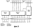
На фиг.3 показана структура УДС в ПУ. Согласно фиг.3, УДС-в 330, т.е. объект УДС для выделенных каналов, выполняет функцию УДС по выделенным логическим каналам, таким как выделенный канал управления (ВКУ) и выделенный канал трафика (ВКТ). Выделенные логические каналы, когда они отображены на выделенный транспортный канал, соединены с выделенным каналом (ВК).Когда выделенные логические каналы отображаются на общий канал, то данные передаются/принимаются к/от УДС-с/о (общего/совместно используемого каналов) 320 через линию соединения УДС-в 330 и УДС-о/с 320. УДС-о/с 320, т.е. объект УДС для общих каналов, обменивается данными по общим логическим каналам, таким как канал управления поискового вызова (КУПВ), канал управления широковещательной передачей (КУШП), общий канал управления (ОКУ), общий канал трафика (ОКТ) и совместно используемый канал управления (СКУ), и обменивается данными с УДС-в 330, с общими транспортными каналами, такими как канал поискового вызова (КПВ), канал прямого доступа (КПД), канал случайного доступа (КСД), общий канал пакетной передачи (ОКП), обратный совместно используемый канал (ОСК) и прямой совместно используемый канал (ПСК). Эти объекты принимают команду управления от объекта УРР через линию управления, показанную на фиг.2, и передают сообщение о состоянии в УРР. Такая информация управления обеспечивается за счет управления УДС.Figure 3 shows the structure of the UDS in PU. According to figure 3, UDS-in 330, i.e. a CDS object for dedicated channels, performs a CDS function on dedicated logical channels, such as a dedicated control channel (VCU) and a dedicated traffic channel (CGT). Dedicated logical channels, when mapped to a dedicated transport channel, are connected to a dedicated channel (VK). When dedicated logical channels are mapped to a common channel, data is transmitted / received to / from UDS-s / o (shared / shared channel) 320 through the connection line of UDS-in 330 and UDS-o / s 320. UDS-o / s 320, i.e. a UDS object for common channels, exchanges data over common logical channels, such as a paging control channel (CCLM), a broadcast control channel (CUS), a common control channel (CCM), a common traffic channel (OCT), and a shared control channel ( SKU), and exchanges data with the UDS-in 330, with common transport channels, such as a paging channel (CPV), a direct access channel (COP), a random access channel (CSD), a common packet transmission channel (OKP), the reverse joint used channel (USC) and direct with jointly channel (CPM). These objects receive a control command from the OAI object through the control line shown in FIG. 2, and transmit a status message to the OAI. Such control information is provided by the management of the MAC.
Существующая структура состоит только из объекта 330 УДС-в (УДС для выделенных каналов) и объекта 320 УДС-о/с (УДС для общих и совместно используемых каналов). Однако когда существующая структура принимает для использования метод ПДВСПЛ, она дополнительно вводит объект 310 УДС-вс (УДС для высокоскоростных каналов), тем самым обеспечивая функцию УДС, поддерживающую высокоскоростной прямой совместно используемый канал (ВС-ПСК). Объект 310 УДС-ВС проектируется для управления от УРР посредством управления УДС. Сообщение, принятое от узла В, восстанавливается в данные за счет обработки сигналов на физическом уровне и принимается в объекте 310 УДС-вс посредством канала передачи ВС-ПСК.The existing structure consists only of the
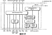
На фиг.4 более детально представлена структура УДС-о/с. Объект УДС-о/с описан более детально со ссылками на Фиг.4. УДС-о/с включает в себя часть “Добавить/считать ИД ПУ” для добавления и считывания идентификатора пользовательского устройства к/из данных, обмен которыми производится с УДС-в; часть “Планирование/обработка приоритета” для передачи транспортных каналов, таких как КСД и ОКП; часть “Выбор ТФ” для выбора типа транспортного формата и часть выбора класса услуги доступа (КУД). Кроме того, объект УДС-о/с включает в себя часть мультиплексирования поля типа целевого канала (ПТЦК) для присоединения поля заголовка для идентификации общих логических каналов к данным и мультиплексирования данных с присоединенным заголовком с соответствующими транспортными каналами и часть “выбор КТФ” для выбора комбинации транспортных форматов при передаче транспортного канала ОСК. При введении метода ПДВСПЛ существующая структура имеет новое соединение с объектом УДС-ВС при сохранении функции существующего объекта УДС-о/с.Figure 4 presents in more detail the structure of the UDS-o / s. The object UDS-o / s described in more detail with reference to Fig.4. UDS-o / s includes the “Add / Read PU ID” part for adding and reading a user device identifier to / from data exchanged with UDS-v; the “Planning / priority processing” part for the transmission of transport channels, such as KSD and OKP; the “TF selection” part for selecting a transport format type; and the access service class (KUD) selection part. In addition, the UDS-o / s object includes a part of multiplexing a field of the type of the target channel (PTCC) for attaching a header field to identify common logical channels to the data and multiplexing data with an attached header with the corresponding transport channels and a part of “selection of CTF” for selection combinations of transport formats when transmitting an OSK transport channel. When introducing the PDVSPL method, the existing structure has a new connection with the UDS-VS object while maintaining the function of the existing UDS-o / s object.
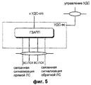
На фиг.5 представлена детальная структура уровня УДС-вс, недавно определенного как метод ПДВСПЛ. Уровень УДС-вс описан ниже более подробно со ссылками на фиг.5. УДС-вс выполняет функцию протокола ГЗАПП посредством канала ВС-ПСК. Т.е. УДС-вс проверяет наличие ошибки в блоке данных, принятом из канала радиосвязи, и выполняет генерацию и передачу сообщения ACK/NACK к УДС-о/с. Этот объект имеет каналы управления радиосвязью “Связанная сигнализация обратной/прямой линий связи”, предназначенные для того, чтобы обмениваться информацией управления ПДВСПЛ с системой UTRAN (Наземная сеть доступа к радиосвязи Универсальной мобильной системы связи).Figure 5 presents a detailed structure of the level of UDS-sun, recently defined as the PDVSPL method. The UDS-Sun level is described in more detail below with reference to FIG. 5. UDS-sun performs the function of the GZAPP protocol through the BC-UCS channel. Those. UDS-sun checks for an error in the data block received from the radio channel and generates and transmits an ACK / NACK message to UDS-o / s. This object has radio control channels “Associated reverse / forward link signaling” designed to exchange PDSPL control information with the UTRAN (Terrestrial Radio Access Network of the Universal Mobile Communications System).
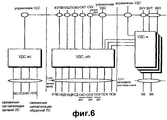
На фиг.6 представлена структура УДС сети. В соответствии с фиг.6, УДС-в предназначен для обмена данными по выделенным логическим каналам ВКТ и ВКУ с использованием выделенного канала ВК и УДС-о/с, подобно УДС-в ПУ. Однако система UTRAN включает в себя множество УДС-в, уникальным образом связанных с ПУ, причем УДС-в связаны с УДС-о/с. УДС-о/с, таким образом, сходны с соответствующими объектами ПУ. Эти объекты все управляются посредством УРР через управление УДС.Figure 6 presents the structure of the MAC network. In accordance with Fig.6, UDS-in is designed to exchange data on dedicated logical channels VKT and VKU using a dedicated channel VK and UDS-o / s, like UDS-in PU. However, the UTRAN system includes many UDS-in, uniquely associated with PU, and UDS-in associated with UDS-o / s. UDS-o / s, thus, are similar to the corresponding PU objects. These facilities are all managed through OAI through UDS management.
С введением метода ПДВСПЛ существующая структура УДС включает в себя объект УДС-вс. Объект УДС-вс предназначен для конфигурирования не в контроллере сети радиосвязи (КСР), а в узле В. Поэтому данные от верхнего уровня передаются через интерфейс lub между КСР и узлом В, а сообщение управления для УДС-вс также передается через интерфейс lub. Объект УДС-вс планирует данные передачи и соединен с каналом передачи ВС-ПСК.With the introduction of the PDVSPL method, the existing UDS structure includes an UDS-sun object. The UDS-vs object is intended for configuration not in the controller of the radio communication network (DAC), but in node B. Therefore, data from the upper level is transmitted via the lub interface between the DAC and node B, and the control message for the UDS-sun is also transmitted through the lub interface. The UDS-sun object schedules transmission data and is connected to the VS-UCS transmission channel.
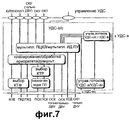
Фиг.7 иллюстрирует функцию существующего объекта УДС-о/с. В соответствии фиг.7, УДС-о/с включает в себя блок функции “Управление потоком УДС-о/с/УДС-в” для обмена данными с УДС-в и функциональный блок “Мультиплексирование ПТЦК/мультиплексирование ИД ПУ” для идентификации между общими логическими каналами КУПВ, КУШП, СКУ, ОКУ, ОКТ и выделенными логическими каналами от УДС-в и для идентификации ПУ. Кроме того, УДС-о/с включает в себя функциональный блок “Планирование/обработка приоритета/демультиплексирование” для общих транспортных каналов” и функциональный блок “Выбор КТФ” для выбора комбинации транспортных форматов (КТФ) в процессе передачи данных по общим транспортным каналам. При передаче данных по каналу передачи ПСК объект УДС-о/с дополнительно включает в себя функциональный блок “Назначение кода прямой линии связи”, который назначает код для использования в канале ПСК прямой линии связи. При дополнительном введении функции ПДВСПЛ добавляется функциональный блок управления потоком для обеспечения маршрутизации блоков передаваемых данных к УДС-вс.7 illustrates the function of an existing UDS-o / s object. In accordance with Fig. 7, the UDS-o / s includes a function block “UDS-o / s / UDS-v flow control” for data exchange with the UDS-v and the “PTCC multiplexing / PU ID multiplexing” function block for identification between common logical channels KUPV, KUSHP, SKU, OKU, OKT and the allocated logical channels from UDS-in and for identification of PU. In addition, the UDS-o / s includes the “Planning / Priority Processing / Demultiplexing” function block for common transport channels ”and the“ CTF Select ”function block for selecting a combination of transport formats (CTF) in the process of transmitting data over common transport channels. When transmitting data over the transmission channel of the UCS, the UDS-o / s object further includes a function block “Assignment of a direct communication line code”, which assigns a code for use in the UCS channel of a direct communication line. With the additional introduction of the PDVSPL function, a flow control functional block is added to provide routing of blocks of transmitted data to the UDS-Sun.
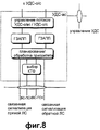
Фиг.8 иллюстрирует функцию объекта УДС-вс более детально. В соответствии с фиг.8, объект УДС-вс имеет функцию обработки блоков данных в канале ВС-ПСК, и управление ресурсами канала для данных ПДВСПЛ также осуществляется данным объектом. Данные, принятые объектом УДС-вс от УДС-о/с (фиг.7), передаются в канал передачи ВС-ПСК через функциональный блок “Управление потоком” для управления потоком принимаемых данных, функциональный блок протокола ГЗАВВ для обработки связанного с ГЗАПП протокола, функциональный блок “Планирования/Обработки приоритета” для определения пункта передачи данных, полученных путем обработки принятых данных в соответствии с протоколом ГЗАПП, и функциональный блок “Выбор КТФ”. В отличие от УДС-в и УДС-о/с, объект УДС-вс конфигурирован в узле В и непосредственно связан с физическим уровнем. Поэтому УДС-вс имеет каналы управления радиосвязью “Связанная сигнализация обратной/прямой линий связи”, предназначенные для того, чтобы обмениваться информацией управления, относящейся к ПДВСПЛ, с ПУ посредством физического уровня.Fig. 8 illustrates the function of a UDS-Sun object in more detail. In accordance with Fig. 8, the UDS-Sun object has a function of processing data blocks in the VS-UCS channel, and channel resource management for the MPAP data is also performed by this object. The data received by the UDS-sun object from UDS-o / s (Fig. 7) is transmitted to the VS-UCS transmission channel through the “Flow control” function block to control the flow of received data, the GZAVV protocol function block for processing the protocol associated with the GZAPP, the “Planning / Processing Priority” function block for determining the data transfer point obtained by processing the received data in accordance with the GZAPP protocol, and the “CTF Choice” function block. Unlike UDS-in and UDS-o / s, the UDS-sun object is configured in node B and is directly connected to the physical layer. Therefore, the UDS-sun has radio control channels “Associated reverse / forward link signaling” designed to exchange control information related to PDSPL with the control unit via the physical layer.
С использованием вышеописанных объектов сообщение управления, необходимое для высокоскоростных пакетных данных услуги, генерируется и передается посредством УЛР, конфигурированного в узле В или ПУ. Затем УЛР приемной стороны анализирует сообщение управления и выполняет необходимые операции в соответствии с результатами анализа. Высокоскоростные пакетные данные услуги требуют короткого блока передачи и быстрого отклика. Однако информационный обмен между УЛР, конфигурированным в КСР, и УЛР, конфигурированным в ПУ, имеет большое время задержки, поскольку связь осуществляется через КСР и узел В. Кроме того, метод ГЗАПП используется для услуги передачи высокоскоростных пакетных данных. В этом случае если необходимо установить в исходное состояние буферную память для ГЗАПП, то должна осуществляться связь между УДС-вс передающей стороны и УДС-вс приемной стороны. Поэтому в настоящем изобретении предлагается способ обеспечения обмена сообщениями между уровнями УДС-вс узла В и ПУ.Using the above-described objects, the control message necessary for high-speed packet service data is generated and transmitted by the HRM configured in the Node B or PU. Then, the HRM of the receiving side analyzes the control message and performs the necessary operations in accordance with the analysis results. High-speed packet data services require a short transmission block and fast response. However, the information exchange between the HRM configured in the DAC and the HRM configured in the UE has a long delay time, since communication is carried out through the DAC and node B. In addition, the GZAPP method is used for the transmission of high-speed packet data. In this case, if it is necessary to initialize the buffer memory for GZAPP, then communication should be made between the UDS-sun of the transmitting side and the UDS-sun of the receiving side. Therefore, the present invention provides a method for providing messaging between UDS-sun levels of node B and UE.
Сущность изобретенияSUMMARY OF THE INVENTION
Задачей настоящего изобретения является создание способа сигнализации между объектами УДС-вс сети и ПУ в системе передачи пакетных данных, использующей метод ПДВСПЛ.The objective of the present invention is to provide a method of signaling between objects UDS-all network and PU in the packet data system using the PDPSL method.
Также задачей настоящего изобретения является создание способа обработки ошибок сообщений сигнализации в N-канале ГЗАПП-OO за счет ввода сигнализации УДС-вс в системе передачи пакетных данных.It is also an object of the present invention to provide a method for error handling of signaling messages in the N-channel of GZAPP-OO by inputting UDS-sun signaling in a packet data transmission system.
Кроме того, задачей настоящего изобретения является создание способа передачи сообщений для установки в исходное состояние УДС-вс при установке в исходное состояние уровня УЛР путем введения сигнализации УДС-вс в системе передачи пакетных данных.In addition, an object of the present invention is to provide a method for transmitting messages for initialization of UDS-vs when initializing the level of HRM by introducing signaling UDS-sun in the packet data transmission system.
В соответствии с первым аспектом изобретения, предложен способ сигнализации между объектом уровня УДС передающего устройства и объектом уровня УДС приемного устройства в системе передачи пакетных данных, включающей в себя передающее устройство и приемное устройство. Способ включает следующие этапы: после приема запроса сигнализации передачу сообщения сигнализации УДС, включающего информацию управления, и индикацию сигнализации, указывающую на передачу информации управления объектом уровня УДС передающего устройства; определение объектом уровня УДС приемного устройства, включает ли сообщение сигнализации УДС индикацию сигнализации, и прием информации управления, включенной в сообщение сигнализации УДС, если сообщение сигнализации УДС включает в себя индикацию сигнализации.According to a first aspect of the invention, there is provided a method for signaling between an object of a MAC layer of a transmitting device and an object of a MAC layer of a receiving device in a packet data transmission system including a transmitting device and a receiving device. The method includes the following steps: after receiving a signaling request, transmitting a CDS signaling message including control information and a signaling indication indicating transmission of control information of a CDS level object of the transmitting device; determining, by the object, the UDS level of the receiving device whether the UDS signaling message includes an alarm indication and receiving control information included in the UDS signaling message if the UDS signaling message includes an alarm indication.
В соответствии со вторым аспектом настоящего изобретения, предлагается способ выполнения сигнализации для объекта уровня УДС приемного устройства объектом уровня УДС передающего устройства под управлением объекта УЛР в системе передачи пакетных данных, содержащей передающее устройство и приемное устройство. Способ включает следующие этапы: если транспортный блок сигнализации получен от объекта УЛР, то генерирование сообщения сигнализации УДС, включающего в себя транспортный блок сигнализации, и индикацию сигнализации, указывающую на передачу транспортного блока сигнализации; если транспортный блок данных получен от объекта УЛР, то генерирование сообщения данных УДС, включающего в себя транспортный блок данных; планирование моментов времени передачи сообщения сигнализации УДС и сообщения данных УДС и передачу сообщения сигнализации УДС и сообщения данных УДС к объекту уровня УДС приемного устройства в соответствующие запланированные моменты времени передачи.In accordance with a second aspect of the present invention, there is provided a method for performing signaling for an object of a receive device MAC layer by an object of a MAC device of a transmitting device under the control of an object of HRM in a packet data transmission system comprising a transmitter and a receiver. The method includes the following steps: if the signaling transport unit is received from the HRM object, then generating a MAC signaling message including the signaling transport unit and an alarm indication indicating transmission of the signaling transport unit; if the data transport block is received from the HRM object, then generating a data message of the MAC, including the data transport block; scheduling transmission times of the UDS signaling message and UDS data messages; and transmitting the UDS signaling message and UDS data message to the UDS layer object of the receiving device at respective scheduled transmission times.
В соответствии с третьим аспектом настоящего изобретения, предложен способ выполнения сигнализации для объекта уровня УДС передающего устройства объектом уровня УДС приемного устройства в системе передачи пакетных данных, содержащей передающее устройство и приемное устройство. Способ включает прием сообщения сигнализации УДС, переданного от объекта уровня УДС передающего устройства, и определение, включает ли в себя сообщение сигнализации УДС индикацию сигнализации, указывающую на передачу информации управления; и прием информации управления, включенной в сообщение сигнализации УДС, если сообщение сигнализации УДС включает в себя индикацию сигнализации.In accordance with a third aspect of the present invention, there is provided a method for performing signaling for an object of a MAC layer of a transmitting device by an object of a MAC layer of a receiving device in a packet data transmission system comprising a transmitting device and a receiving device. The method includes receiving a CDS signaling message transmitted from a CDS layer object of the transmitting device, and determining whether the CDS signaling message includes a signaling indication indicating transmission of control information; and receiving control information included in the MAC signaling message if the MAC signaling message includes an alarm indication.
Краткое описание чертежейBrief Description of the Drawings
Вышеуказанные задачи, признаки и преимущества настоящего изобретения поясняются в последующем детальном описании, иллюстрируемом чертежами, на которых представлено следующее:The above objectives, features and advantages of the present invention are explained in the following detailed description, illustrated by the drawings, which represent the following:
Фиг.1 - иллюстрация передачи/приема в обычной системе связи МДКР, использующей ПДВСПЛ;Figure 1 - illustration of the transmission / reception in a conventional communication system mdcr using PDSP;
Фиг.2 - иллюстрация обобщенной многоуровневой структуры в системе связи МДКР;Figure 2 - illustration of a generalized multi-level structure in a communication system mdcr;
Фиг.3 - обобщенная структура уровня УДС в многоуровневой структуре протокола ПУ, поддерживающего ПДВСПЛ;Figure 3 - a generalized structure of the level of UDS in the multi-level structure of the Protocol PU, supporting PDSP;
Фиг.4 - детальная структура уровня УДС-о/с, показанного на фиг.3;Figure 4 is a detailed structure of the level of UDS-o / s shown in figure 3;
Фиг.5 - детальная структура уровня УДС-вс, показанного на фиг.3;Figure 5 is a detailed structure of the level of UDS-Sun shown in figure 3;
Фиг.6 - обобщенная структура уровня УДС в многоуровневой структуре протокола сети, поддерживающей ПДВСПЛ;6 is a generalized structure of the MAC layer in a multi-level protocol structure of a network supporting PDAP;
Фиг.7 - детальная структура уровня УДС-о/с, показанного на фиг.6;Fig.7 is a detailed structure of the level of UDS-o / s shown in Fig.6;
Фиг.8 - детальная структура уровня УДС-о/с, показанного на фиг.6;Fig.8 is a detailed structure of the level of UDS-o / s shown in Fig.6;
Фиг.9 - обмен информацией сигнализации УДС между объектами УДС-вс в системе связи МДКР, поддерживающей ПДВСПЛ, в соответствии с возможным вариантом осуществления настоящего изобретения;Figure 9 - exchange of information signaling UDS between objects UDS-Sun in a communication system mdcr supporting PDSP, in accordance with a possible embodiment of the present invention;
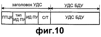
Фиг.10 - формат блока данных протокола (БДП) УДС в существующей системе связи МДКР, не поддерживающей ПДВСПЛ;Figure 10 - format of the Protocol data unit (BDP) UDS in the existing communication system mdcr that does not support PDSP;
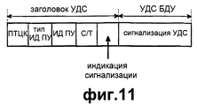
Фиг.11 - формат БДП УДС в системе связи МДКР, поддерживающей ПДВСПЛ, в соответствии с возможным вариантом осуществления настоящего изобретения;11 is a format BDP UDS in the communication system mdcr supporting PDAP, in accordance with a possible embodiment of the present invention;
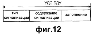
Фиг.12 - пример формата полезной нагрузки УДС, показанной на фиг.11;Fig. 12 is an example of a UDS payload format shown in Fig. 11;
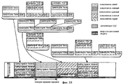
Фиг.13 - иллюстрация способа передачи транспортного блока сигнализации УДС по каналу ВС-ПСК прямой линии связи вместе с обобщенным транспортным блоком данных в соответствии с возможным вариантом осуществления настоящего изобретения;13 is an illustration of a method for transmitting a UDS signaling transport block over a BC-UCS direct link channel together with a generalized data transport block in accordance with a possible embodiment of the present invention;
Фиг.14А - процедура приема и обработки данных или запроса сигнализации УДС от УЛР объектом УДС-вс узла В в соответствии с возможным вариантом осуществления настоящего изобретения;FIG. 14A illustrates a procedure for receiving and processing data or a signaling request for UDS from an ULR by an UDS-sun entity of node B in accordance with a possible embodiment of the present invention; FIG.
Фиг.14В - процедура определения необходимости передачи сигнализации объектом УДС-вс и выполнения передачи сигнализации УДС в соответствии с возможным вариантом осуществления настоящего изобретения;FIG. 14B illustrates a procedure for determining the need for signaling to be transmitted by an UDS-sun entity and performing signaling transmission of UDS in accordance with a possible embodiment of the present invention;
Фиг.15 - диаграмма потока сигналов, иллюстрирующая процедуру обмена информацией установки в исходное состояние между уровнями УДС-вс в системе связи МДКР, поддерживающей ПДВСПЛ;FIG. 15 is a signal flow diagram illustrating a procedure for exchanging initial setup information between CDS-BC levels in a CDMA communication system supporting PDCPL;
Фиг.16 - диаграмма потока сигналов, иллюстрирующая процедуру приема транспортного блока сигнализации УДС в ПУ в системе связи МДКР, поддерживающей СКВСПЛ, в соответствии с возможным вариантом осуществления настоящего изобретения;FIG. 16 is a signal flow diagram illustrating a procedure for receiving a UDS signaling transport unit in a UE in a CDMA communication system supporting SQSS, in accordance with a possible embodiment of the present invention; FIG.
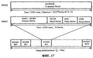
Фиг.17 - иллюстрация обобщенной структуры обратного выделенного физического канала в системе связи МДКР;17 is an illustration of a generalized structure of a reverse dedicated physical channel in a CDMA communication system;
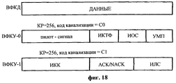
Фиг.18 - иллюстрация обобщенной структуры обратного выделенного физического канала в системе связи МДКР, поддерживающей ПДВСПЛ;Fig. 18 is an illustration of a generalized structure of a reverse dedicated physical channel in a CDMA communication system supporting PDSS;
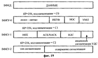
Фиг.19 - иллюстрация структуры обратного выделенного физического канала в системе связи МДКР, поддерживающей ПДВСПЛ, в соответствии с возможным вариантом осуществления настоящего изобретения;FIG. 19 is an illustration of a structure of a reverse dedicated physical channel in a CDMA communication system supporting PDAP, in accordance with a possible embodiment of the present invention; FIG.
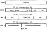
Фиг.20 - иллюстрация другой структуры обратного выделенного физического канала в системе связи МДКР, поддерживающей ПДВСПЛ, в соответствии с возможным вариантом осуществления настоящего изобретения;FIG. 20 is an illustration of another reverse physical channel structure in a CDMA communication system supporting PDAP, in accordance with a possible embodiment of the present invention; FIG.
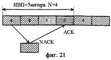
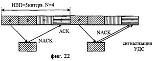
Фиг.21 - иллюстрация ошибки, возникающей в сигнале ACK/NACK, когда в системе связи МДКР, поддерживающей ПДВСПЛ, используется режим синхронного/синхронного ГЗАПП, иFIG. 21 is an illustration of an error occurring in an ACK / NACK signal when a synchronous / synchronous GZAPP mode is used in a CDMA communication system supporting PDCPL, and
Фиг.22 - иллюстрация способа коррекции ошибки посредством сигнализации объектом УДС-вс ПУ при возникновении ошибки NACK в режиме синхронного/синхронного ГЗАПП в соответствии с возможным вариантом осуществления настоящего изобретения.Fig. 22 is an illustration of a method for error correction by signaling by an object of a UDS-Sun PU when a NACK error occurs in the synchronous / synchronous GZAP mode in accordance with a possible embodiment of the present invention.
Детальное описание предпочтительного варианта осуществления настоящего изобретенияDetailed Description of a Preferred Embodiment of the Present Invention
Предпочтительный вариант осуществления настоящего изобретения описан ниже со ссылками на чертежи. В последующем описании хорошо известные функции или конструкции не описаны детально, чтобы не затенять сущность изобретения ненужными деталями.A preferred embodiment of the present invention is described below with reference to the drawings. In the following description, well-known functions or constructions are not described in detail so as not to obscure the invention with unnecessary details.
Настоящее изобретение предусматривает устройство и способ для генерации информации сигнализации объектом УДС-вс передающей стороны и передачи блока данных с сигнализацией посредством УДС-вс вместе с битом индикации сигнализации, введенным в заголовок УДС. Кроме того, настоящее изобретение обеспечивает устройство и способ для приема блока данных с сигнализацией посредством объекта УДС-вс приемной стороной и распознавания принятого блока данных.The present invention provides a device and method for generating signaling information by an object of a UDS-sun transmitting side and transmitting a data unit with signaling by a UDS-sun together with a signaling indication bit inserted in the UDS header. In addition, the present invention provides an apparatus and method for receiving a data block with signaling by an UDS-Sun object by a receiving side and recognizing a received data block.
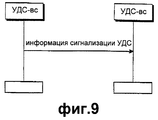
Фиг.9 иллюстрирует обмен информацией сигнализации между объектами УДС-вс в соответствии с возможным вариантом осуществления настоящего изобретения. В общем случае уровень УДС присоединяет заголовок УДС к блоку данных (или БДП УЛР), передаваемому от уровня УЛР, для генерирования тем самым транспортного блока. На фиг.10 иллюстрируется формат БДП УДС в существующей системе МДКР, не использующей ПДВСПЛ. БДП УДС состоит из заголовка УДС и полезной нагрузки. Заголовок УДС состоит из поля типа целевого канала (ПТЦК), типа ИД-ПУ, ИД-ПУ и поля С/Т. ПТЦК представляет собой поле, предназначенное для различения типа логического канала, поля типа ИД-ПУ и ИД-ПУ указывают тип идентификации и идентификацию ПУ соответственно. Поле С/Т является индикацией, обеспечивающей различение логического канала в том же самом транспортном канале.Fig.9 illustrates the exchange of signaling information between objects UDS-Sun in accordance with a possible embodiment of the present invention. In general, the UDS layer attaches the UDS header to a data block (or BEL of the HRM) transmitted from the HRM layer, thereby generating a transport block. Figure 10 illustrates the format of the BJP UDS in the existing system mdcr, not using PDVSPL. BDP UDS consists of a UDS header and a payload. The UDS header consists of a field of the type of the target channel (PTTC), type ID-PU, ID-PU and the C / T field. PTTC is a field designed to distinguish between the type of logical channel, the fields of type ID-PU and ID-PU indicate the type of identification and identification of the PU, respectively. The C / T field is an indication that distinguishes a logical channel in the same transport channel.
На фиг.11 иллюстрируется формат УДС с сигнализацией УДС согласно возможному варианту осуществления настоящего изобретения. Как показано на фиг.11, заголовок УДС в соответствии с возможным вариантом осуществления настоящего изобретения имеет поле индикации сигнализации УДС в дополнение к имеющейся информации заголовка. Например, в случае, когда поле индикации состоит из одного бита, если поле индикации представляет собой “0”, то это указывает на обычный БДП УДС. Однако если поле индикации представляет собой “1”, то блок данных услуги (БДУ) УДС состоит только из информации управления для сигнализации УДС. Поле индикации сигнализации УДС может быть расположено в различных положениях заголовка УДС, причем положение поля индикации не ограничено.11 illustrates a CDS format with CDS signaling according to a possible embodiment of the present invention. As shown in FIG. 11, the MAC header in accordance with a possible embodiment of the present invention has a MAC alarm indication field in addition to the available header information. For example, in the case where the display field consists of one bit, if the display field is “0”, then this indicates a normal BDS UDS. However, if the display field is “1”, then the UDS service data unit (NDU) consists only of control information for UDS signaling. The UDS signaling indication field may be located at different positions of the UDS header, wherein the position of the indication field is not limited.
На фиг.12 показан формат полезной нагрузки УДС или БДУ УДС информации управления сигнализации УДС в соответствии с возможным вариантом осуществления настоящего изобретения. Согласно фиг.12, БДУ УДС включает в себя поле типа сигнализации для различения типа сообщения сигнализации в УДС-вс и поле содержания сигнализации, содержащее информацию управления соответствующего сообщения. Кроме того, БДУ УДС содержит биты заполнения для заполнения блока данных.12 shows a payload format of a UDS or UDU UDS of UDS signaling control information in accordance with a possible embodiment of the present invention. According to FIG. 12, the MAC UDD includes a signaling type field for distinguishing a type of signaling message in the MAC-Sun and a signaling content field containing control information of the corresponding message. In addition, the CDU UDD contains padding bits to populate the data block.
Настоящее изобретение обеспечивает прямую схему сигнализации от одного объекта УДС-вс к другому объекту УДС-вс. Прямая линия связи и обратная линия связи используют различные физические каналы. Поэтому описание способа сигнализации будет приведено отдельно для прямой и обратной линий связи.The present invention provides a direct signaling scheme from one UDS-sun object to another UDS-sun object. The forward link and reverse link use different physical channels. Therefore, a description of the signaling method will be given separately for the forward and reverse links.
Во-первых, в случае прямой линии связи блок данных сигнализации УДС может быть передан по каналу ВС-ПСК. Это описано ниже со ссылками на фиг.13.Firstly, in the case of a direct communication line, the UDS signaling data block can be transmitted via the BC-UCS channel. This is described below with reference to FIG.
Фиг.13 иллюстрирует способ передачи транспортного блока сигнализации УДС по каналу ВС-ПСК прямой линии связи вместе с общим транспортным блоком данных. Канал ВС-ПСК передает множество блоков данных ПУ на интервале времени передачи (ИВП) на основе временного разделения. Как вариант, множество блоков данных ПУ в одном ИВП может быть сегментировано на блочные коды до их передачи. Заголовок присоединяется объектом УДС-вс к блоку данных, передаваемому к УДС-вс после его сегментирования объектом УЛР. При этом генерируется транспортный блок данных. Транспортные блоки данных ПУ распределяются по множеству кодов в ИВП с использованием функции планирования, выполняемой объектом УДС-вс, перед передачей. Если требуется сигнализация посредством УДС-вс, то транспортный блок сигнализации генерируется в структуре, показанной на фиг.11. Сформированный транспортный блок сигнализации передается по каналу ВС-ПСК вместе с транспортным блоком данных ПУ, запрашивающего сигнализацию.Fig. 13 illustrates a method for transmitting a UDS signaling transport block over a BC-UCS forward link channel together with a common data transport block. The BC-UCS channel transmits a plurality of PU data blocks over a transmission time interval (TTI) based on time division. Alternatively, a plurality of PU data blocks in one TIU can be segmented into block codes before they are transmitted. The header is attached by the UDS-sun object to the data block transmitted to the UDS-sun after it is segmented by the OHRM object. This generates a data transport block. The transport data blocks of the PU are distributed across a plurality of codes in the TRP using the scheduling function performed by the UDS-sun object before transmission. If signaling by UDS-Sun is required, then the signaling transport block is generated in the structure shown in FIG. 11. The generated signaling transport block is transmitted via the BC-UCS channel together with the transport data block of the control unit requesting the signaling.
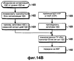
На фиг.14А показана процедура приема и обработки данных или запрос сигнализации УДС от УЛР узлом В в соответствии с возможным вариантом осуществления настоящего изобретения. В соответствии с фиг.14А, объект УДС-вс принимает транспортный блок данных (или БДП УЛР) от УЛР на этапе 1407. УДС-вс присоединяет заголовок УДС к принятому БДП УЛР на этапе 1409. УДС-вс принимает сигнал индикации сигнализации УДС, указывающий на запрос сигнализации УДС, от УЛР на этапе 1401. После приема запроса сигнализации УДС объект УДС-вс переходит к этапу 1403, где он генерирует транспортный блок сигнализации УДС или сообщение сигнализации УДС для информации сигнализации УДС. После этого на этапе 1405 объект УДС-вс присоединяет заголовок УДС с битом индикации, указывающим на сигнализацию УДС, к сообщению сигнализации УДС. Заголовок УДС, присоединенный на этапе 1405, представляющий собой заголовок, указывающий на сигнализацию, должен отличаться от заголовка УДС, присоединяемого на этапе 1409. На этапе 1411 объект УДС-вс планирует момент времени, когда должен передаваться БДП УЛР или сообщение сигнализации УДС с заголовком УДС или БДП УЛР и сообщение сигнализации УДС. Здесь сообщение сигнализации УДС может иметь приоритет над блоком данных БДП УЛР. Если момент времени определен посредством указанного планирования, то объект УДС-вс переходит к этапу 1413, на котором он передает БДП УЛР или сообщение сигнализации УДС к ПУ на каждом ИВП.On figa shows the procedure for receiving and processing data or request signaling MAC from the HRM node B in accordance with a possible embodiment of the present invention. In accordance with FIG. 14A, the UDS-Sun object receives a data transport unit (or UHF BDF) from the HRM in
До сих пор процедура приема сигнала от УЛР объектом УДС-вс и передачи принятого сигнала к ПУ была описана со ссылками на фиг. 14А. Далее процедура обнаружения необходимости передачи сигнализации объектом УДС-вс и выполнения передачи сигнализации УДС в соответствии с возможным вариантом осуществления настоящего изобретения описывается со ссылками на фиг.14В.Until now, the procedure for receiving a signal from an HRM by a UDS-Sun object and transmitting the received signal to the UE has been described with reference to FIG. 14A. Next, a procedure for detecting the need for signaling to be transmitted by a UDS-Sun entity and performing signaling transmission of the UDS in accordance with a possible embodiment of the present invention is described with reference to FIG.
Согласно фиг.14В, если на уровне УДС-вс определено, что необходима сигнализация УДС-вс, то объект УДС-вс на этапе 1420 определяет сигнализацию УДС для соответствующего ему объекта УДС-вс. После определения сигнализации УДС объект УДС-вс переходит к этапу 1422, где он генерирует транспортный блок сигнализации УДС для информации сигнализации. На этапе 1424 УДС-вс устанавливает индикацию сигнализации в заголовке УДС для индикации сигнализации и присоединяет заголовок УДС к транспортному блоку сигнализации УДС. На этапе 1426 объект УДС-вс принимает от УЛР блок данных (или БДП УЛР). На этапе 1428 объект УДС-вс присоединяет общий заголовок УДС (фиг.10) к блоку данных или БДП УЛР, принятому от УЛР. На этапе 1430 УДС-вс планирует передачу блока данных с присоединенным заголовком и/или транспортного блока сигнализации УДС. На этапе 1432 УДС-вс передает блок данных или транспортный блок сигнализации УДС к ПУ в запланированный момент времени для каждого ИВП.According figv, if at the level of UDS-Sun it is determined that signaling UDS-sun, the object UDS-sun at
Процедуры, представленные на фиг.14А и 14В, могут быть различным образом использованы, когда от одного объекта УДС-вс требуется передача сообщения сигнализации к соответствующему ему объекту УДС-вс. Процедура обмена информацией установки в исходное состояние между объектами УДС-вс описана ниже со ссылками на фиг.15.The procedures shown in FIGS. 14A and 14B can be used in various ways when a signaling message is required from one UDS-sun object to its corresponding UDS-sun object. The procedure for exchanging initialization information between UDS-Sun objects is described below with reference to FIG.
Во-первых, представлено описание процесса установки в исходное состояние на уровне УДС-вс, дополнительно введенном при использовании метода ПДВСПЛ в возможном варианте осуществления настоящего изобретения. Обычный процесс установки в исходное состояние УЛР определяется для обработки ошибок протокола в системе связи Ш-МДКР, не использующей ПДВСПЛ. Однако обычный процесс установки в исходное состояние УЛР вызывает ненужные передачи данных на уровне УДС ввиду использования метода ПДВСПЛ. Когда используется ПДВСПЛ, то требуется новый уровень УДС, т.е. уровень УДС-вс для поддержки ПДВСПЛ, и когда уровень УДС-вс выполняет функцию ГЗАПП, узел В должен выполнять функцию буферизации для передачи и повторной передачи блоков данных. Поэтому блок данных, переданный из УЛР, буферизуется (временно сохраняется) на уровне УДС-вс, прежде чем передаваться по каналу радиосвязи. В этот момент, если выполняется процесс установки в исходное состояние УЛР, вследствие ошибки протокола, возникающей в УЛР, буферизованный на уровне УДС-вс блок данных до процесса установки в исходное состояние УЛР передается к соответствующему уровню УДС-вс по физическому каналу. Однако если соответствующий уровень УДС-вс, т.е. уровень УДС-вс на приемной стороне, принимает блок данных, то этот блок данных игнорируется на уровне УЛР на приемной стороне в соответствии с процессом установки в исходное состояние УЛР. Поэтому когда выполняется процесс установки в исходное состояние УЛР, передача блока данных уровнем УДС-вс является ненужной передачей. Кроме того, блок данных буферизуется до завершения процесса установки в исходное состояние УЛР, вызывая излишнее использование памяти. Кроме того, уровень УДС-вс приемной стороны должен также сбросить информацию повторной передачи. Это объясняется тем, что когда блоки данных или пакеты данных, принятые от системы UTRAN, включают в себя блок данных, в котором обнаружена ошибка на уровне УДС-вс, то УДС-вс должен временно выполнить буферизацию для повторной передачи ошибочного блока данных. В результате память уровня УДС-вс приемной стороны используется избыточным образом, и ошибочный блок данных также избыточным образом передается к верхнему уровню или уровню УЛР приемной стороны.Firstly, a description is given of the initialization process at the UDS-Sun level, additionally introduced using the PDSPL method in a possible embodiment of the present invention. The normal process of initializing the HRM is determined to handle protocol errors in a W-CDMA communication system that does not use PDSPL. However, the normal process of initializing the HRM causes unnecessary data transfers at the MAC level due to the use of the PDLSP method. When PDVSPL is used, a new level of MAC is required, i.e. the UDS-sun level to support PDSPL, and when the UDS-sun level performs the GZAPP function, the node B must fulfill the function of buffering for the transmission and retransmission of data blocks. Therefore, the data block transmitted from the HRM is buffered (temporarily stored) at the UDS-Sun level before being transmitted over the radio channel. At this point, if the process of initializing the HRM is carried out, due to a protocol error that occurs in the HRM, the data block buffered at the UDS-Sun level is transferred to the corresponding UDS-sun level through the physical channel prior to the initial installation process. However, if the appropriate level of UDS-Sun, i.e. level UDS-vs on the receiving side, receives a data block, then this data block is ignored at the level of HRM on the receiving side in accordance with the installation process in the initial state of the HRM. Therefore, when the installation process in the initial state of the HRM is performed, the transfer of the data block by the MAC-Sun level is an unnecessary transmission. In addition, the data block is buffered until the initial installation of the HRM is completed, causing excessive memory usage. In addition, the receiver-side MAC-sun level should also reset the retransmission information. This is because when the data blocks or data packets received from the UTRAN system include a data block in which an error is detected at the MAC-sun level, the MAC-Sun should temporarily execute buffering to retransmit the erroneous data block. As a result, the memory of the UDS-vs level of the receiving side is used redundantly, and the erroneous data block is also redundantly transmitted to the upper level or the HRR level of the receiving side.
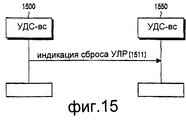
На фиг.15 представлена диаграмма потока сигналов, иллюстрирующая процедуру обмена информацией установки в исходное состояние между уровнями УДС-вс, основанную на процессе установки в исходное состояние УДС. Если объект УДС-вс передающей стороны устанавливается в исходное состояние, когда УЛР передающей стороны устанавливается в исходное состояние, то все блоки данных, сохраненные в объекте УДС-вс передающей стороны, отбрасываются. Соответственно, соответствующие блоки данных, сохраненные в УДС-вс передающей стороны и УДС приемной стороны, не являются необходимыми, так что они должны быть отброшены. Поэтому объект УДС-вс приемной стороны также должен быть установлен в исходное состояние, когда УДС-вс передающей стороны устанавливается в исходное состояние. С этой целью на фиг.15 УДС-вс 1500 передающей стороны передает информацию установки в исходное состояние “Индикация сброса УЛР” 1511, указывающую на то, что объект УДС-вс 1500 передающей стороны установлен в исходное состояние, к объекту УДС-вс 1550 приемной стороны. После приема информации установки в исходное состояние объект УДС-вс 1550 приемной стороны стирает соответствующие блоки данных, сохраненные в его внутренней памяти, и затем устанавливается в исходное состояние. Здесь в качестве сообщения, указывающего информацию установки в исходное состояние, передаваемую от УДС-вс 1500 передающей стороны к УДС-вс 1550 приемной стороны, используется сообщение сигнализации УДС-вс между уровнями УДС-вс.On Fig presents a diagram of the signal flow illustrating the procedure for the exchange of information of the installation in the initial state between the levels of UDS-Sun, based on the installation process in the initial state of the UDS. If the object of the UDS-sun of the transmitting side is set to the initial state when the HRR of the transmitting side is set to the initial state, then all data blocks stored in the object of the UDS-sun of the transmitting side are discarded. Accordingly, corresponding data blocks stored in the UDS-sun of the transmitting side and the UDS of the receiving side are not necessary, so they must be discarded. Therefore, the object of the UDS-sun of the receiving side must also be set to the initial state when the UDS-sun of the transmitting side is set to the initial state. To this end, in Fig. 15, the UDS-
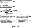
На фиг.16 иллюстрируется процедура приема транспортного блока сигнализации УДС, передаваемого объектом УДС-вс в сети радиосвязи пользовательским устройством (ПУ) в соответствии с возможным вариантом осуществления настоящего изобретения. Согласно фиг.16, после приема блока данных, переданного объектом УДС-вс сети на этапе 1601, объект УДС-вс ПУ переходит к этапу 1602, где он проверяет заголовок УДС, включенный в принятый блок данных. После этого УДС-вс на этапе 1603 определяет, является ли каждый транспортный блок данных данными или информацией сигнализации, основываясь на результатах проверки. Если блок данных является информацией сигнализации, то УДС-вс переходит к этапу 1604, на котором из информации сигнализации удаляется заголовок УДС. После этого на этапе 1605 УДС-вс исполняет информацию сигнализации с удаленным заголовком УДС, т.е. порядок информации управления.FIG. 16 illustrates a procedure for receiving a UDS signaling transport block transmitted by a UDS-sun entity in a radio network by a user equipment (UE) in accordance with a possible embodiment of the present invention. According to FIG. 16, after receiving the data block transmitted by the MAC-sun network entity in
Однако если блок данных представляет собой информацию данных, на этапе 1606 УДС-вс удаляет заголовок УДС из информации данных и затем переходит к этапу 1607. На этапе 1607 УДС-вс передает информацию данных с удаленным заголовком УДС. Информация данных с удаленным заголовком УДС представляет собой БДУ УДС, при этом БДУ УДС передается посредством УДС-вс к объекту УЛР более высокого уровня.However, if the data block is data information, at 1606, the MAC-Sun removes the MAC header from the data information and then proceeds to 1607. At 1607, the MAC-Sun transmits data information with the MAC header removed. The data information with the UDS remote header is a UDS NOS, while the UDS NOS is transmitted via UDS-Sun to a higher level HRM object.
До сих пор описывался способ передачи сигнализации УДС для прямой линии связи. Ниже описан способ передачи сигнализации УДС для обратной линии связи. Передача сигнализации УДС для обратной линии связи может быть выполнена с использованием дополнительного выделенного физического канала управления (ВФКУ) в ответ на запрос сигнализации УДС.So far, a method for transmitting UDS signaling for a forward link has been described. The following describes a method for transmitting UDS signaling for the reverse link. The UDS signaling transmission for the reverse link can be performed using an additional dedicated physical control channel (UFCI) in response to the UDS signaling request.
На фиг.17 представлена структура обобщенного обратного выделенного физического канала (ВФК). Согласно фиг.17, один кадр радиосвязи с периодом Tf=10 мс содержит 15 временных интервалов, и выделенный физический канал данных (ВФКД) на интервал имеет Nданные битов в соответствии с коэффициентом расширения (КР). Выделенный физический канал управления (ВФКУ) на интервал содержит биты пилот-сигнала, указателя комбинации транспортных форматов (УКТФ), информации обратной связи (ИОС) и управления мощностью передачи (УМП), причем КР фиксирован на значении 256.On Fig presents the structure of a generalized reverse dedicated physical channel (VFC). According to FIG. 17, one radio frame with a period T f = 10 ms contains 15 time slots, and a dedicated physical data channel (VFKD) per interval has N bit data in accordance with an expansion coefficient (KR). A dedicated physical control channel (VFCI) for the interval contains the bits of the pilot signal, a pointer to a combination of transport formats (UKF), feedback information (IOS) and transmit power control (SAR), and the RC is fixed at 256.
Фиг.18 иллюстрирует структуру обратного выделенного физического канала (ВФК), когда используется ПДВСПЛ. Как показано на фиг.18, обратный выделенный физический канал содержит индикацию качества канала (ИКК), подтверждение/неподтверждение (ACK/NACK), являющееся индикацией подтверждения ГЗАПП, и индикацию лучшей сотовой ячейки (ИЛС) для выбора лучшей сотовой ячейки для БВС, в дополнение к битам управления по фиг.17. Структура канала по фиг.18 использует мультиплексирование за счет кодового разделения каналов (МКР), принимая во внимание совместимость с существующей системой, не использующей ПДВСПЛ. Т.е. обратный выделенный физический канал передает биты информации ИКК, ACK/NACK, ИЛС для ПДВСПЛ путем назначения новых кодов, в то же время поддерживая обобщенный выделенный физический канал управления ВФКУ-0.FIG. 18 illustrates a structure of a reverse dedicated physical channel (VFC) when an MPAP is used. As shown in FIG. 18, the reverse dedicated physical channel contains an indication of channel quality (ACI), acknowledgment / non-acknowledgment (ACK / NACK), which is an indication of GZAPP acknowledgment, and an indication of the best cell (ILS) for selecting the best cell for BWS, in addition to the control bits of FIG. The channel structure of FIG. 18 uses multiplexing due to code division multiplexing (MCD), taking into account compatibility with an existing system that does not use PDCPL. Those. the reverse dedicated physical channel transmits bits of information CQI, ACK / NACK, ILS for PDSPL by assigning new codes, while maintaining a generalized dedicated physical control channel VFKU-0.
Фиг.19 иллюстрирует способ передачи сигнализации УДС по обратной линии связи в соответствии с возможным вариантом осуществления настоящего изобретения. В соответствии с фиг.19, поле для передачи индикации сигнализации УДС добавлено к выделенному физическому каналу управления ВФКУ-1 для поддержки ПДВСПЛ. Тем временим информация сигнализации (или содержание) того типа, который подобен типу сигнализации УДС для прямой линии связи, описанной со ссылками на фиг.12, передается на основе МКР путем назначения нового кода обратной линии связи (указывающего на ВФКУ-2). Индикация сигнализации УДС в выделенном физическом канале управления ВФКУ-1 указывает на наличие/отсутствие информации управления сигнализацией УДС. Если указывается ее наличие этой индикацией, то информация управления сигнализацией УДС передается по выделенному физическому каналу управления ВФКУ-2. Эта информация управления включает в себя тип сигнализации и содержание необходимой информации управления.FIG. 19 illustrates a method for transmitting CDS signaling on a reverse link in accordance with a possible embodiment of the present invention. In accordance with Fig. 19, a field for transmitting an indication of signaling of the UDS is added to the dedicated physical control channel of the VFKU-1 to support PDSPL. In the meantime, signaling information (or content) of a type that is similar to the type of UDS signaling for the forward link described with reference to FIG. 12 is transmitted based on the FSC by assigning a new reverse link code (pointing to BFC-2). The UDS signaling indication in the dedicated physical control channel VFKU-1 indicates the presence / absence of UDS signaling control information. If its presence is indicated by this indication, then the UDS alarm control information is transmitted via the dedicated physical control channel VFKU-2. This control information includes the type of signaling and the content of the necessary control information.
Фиг.20 иллюстрирует другой возможный способ передачи сигнализации УДС посредством обратной линии связи в соответствии с возможным вариантом осуществления настоящего изобретения. В соответствии с фиг.20, в этом способе сначала выбирается код, соответствующий ВФКУ-2, для передачи информации сигнализации УДС и затем приемнику в сети разрешается определять наличие/отсутствие сигнализации УДС на основе принятого уровня мощности вместо определения наличия/отсутствия сигнализации УДС посредством индикации сигнализации УДС согласно фиг.19. Этот способ сигнализации УДС может быть использован при исправлении ошибки в сообщении подтверждения АСК ГЗАПП в УДС-вс и передаче информации установки в исходное состояние УДС-вс.FIG. 20 illustrates another possible method for transmitting CDS signaling via a reverse link in accordance with a possible embodiment of the present invention. In accordance with Fig. 20, in this method, the code corresponding to the BFCI-2 is first selected for transmitting UDS signaling information and then the receiver in the network is allowed to determine the presence / absence of UDS signaling based on the received power level instead of determining the presence / absence of UDS signaling by indicating signaling UDS according to Fig.19. This method of signaling UDS can be used to correct errors in the confirmation message ASK GZAPP in UDS-sun and transfer the installation information to the initial state of UDS-sun.
Фиг.21 иллюстрирует ошибку, возникающую в сигнале ACK/NACK, когда используется синхронный/синхронный ГЗАПП. При синхронном/синхронном ГЗАПП сигнал ACK/NACK передается по обратной линии связи для каждого транспортного блока данных, передаваемого по прямой линии связи в ИВП. Хотя ПУ передает сигнал NACK в сеть ввиду ошибки, возникающей в принятом транспортном блоке данных “а”, сеть может принять сигнал АСК вследствие ошибки в канале радиосвязи. В этом случае сеть передает новый блок данных “е”, и ПУ ошибочно принимает новый блок данных “е” за повторно переданный блок данных, относящийся к ошибочному блоку данных “а”, объединяет принятый блок данных “е” с ранее принятым блоком данных “а” и принимает ошибочное решение, что вновь произошла ошибка. Поэтому ПУ передает сообщение NACK (или сообщение запроса повторной передачи), и сеть принимает ошибочное решение, что ошибка произошла в переданном блоке данных “е”. По этой причине в процедуре синхронного/синхронного ГЗАПП ошибка не может быть скорректирована.21 illustrates an error occurring in an ACK / NACK signal when a synchronous / synchronous GAPP is used. In synchronous / synchronous GZAPP, the ACK / NACK signal is transmitted on the reverse link for each data transport block transmitted over the forward link to the TTI. Although the control unit transmits the NACK signal to the network due to an error occurring in the received data transport block “a”, the network may receive the ACK signal due to an error in the radio channel. In this case, the network transmits a new data block “e”, and the PU mistakenly accepts a new data block “e” as a retransmitted data block related to the erroneous data block “a”, combines the received data block “e” with the previously received data block “ a ”and makes an erroneous decision that an error has occurred again. Therefore, the PU transmits a NACK message (or a retransmission request message), and the network makes an erroneous decision that an error has occurred in the transmitted data block “e”. For this reason, the error cannot be corrected in the synchronous / synchronous GZAPP procedure.
Фиг.22 иллюстрирует способ коррекции ошибки путем сигнализации посредством УДС-вс ПУ (или принимающей стороны), когда ошибка NACK возникает в синхронном/синхронном ГЗАПП в соответствии с возможным вариантом осуществления настоящего изобретения. При передаче сообщения NACK посредством сигнализации УДС в этом способе передается второе или последующее переданное сообщение NACK для того же самого блока данных вместе с информацией сигнализации, содержащей частоту передачи, так что сеть может распознать, что ранее переданный блок данных “а” должен быть передан повторно.FIG. 22 illustrates a method for error correction by signaling by UDS-Sun of the UE (or the receiving side) when a NACK error occurs in a synchronous / synchronous GZAPP in accordance with a possible embodiment of the present invention. When transmitting a NACK message by UDS signaling, in this method a second or subsequent transmitted NACK message is transmitted for the same data block together with signaling information containing the transmission frequency, so that the network can recognize that the previously transmitted data block “a” must be retransmitted .
Как описано выше, настоящее изобретение может обеспечить эффективную передачу информации управления, которой следует обмениваться непосредственно между уровнями УДС-вс. Например, настоящее изобретение может обеспечить коррекцию ошибки ACK/NACK в синхронном/синхронном ГЗАПП и передачу информации установки в исходное состояние на уровне УДС-вс. Для обеспечения возможности сигнализации между уровнями УДС согласно настоящему изобретению, для того чтобы объект УДС, находящийся в контроллере сети радиосвязи, поддерживал ПДВСПЛ в сети, поддерживающей ПДВСПЛ, УДС-вс помещается в узле В, и УДС-вс дополнительно выполняет функцию ГЗАПП, помимо обычной функции объекта УДС, так что может оказаться необходимым обмен обобщенным сообщением сигнализации, а также новым сообщением сигнализации.As described above, the present invention can provide efficient transmission of control information that should be exchanged directly between levels of UDS-sun. For example, the present invention can provide ACK / NACK error correction in synchronous / synchronous GAPP and transfer of the installation information to the initial state at the UDS-Sun level. In order to enable signaling between the levels of the UDS according to the present invention, in order for the UDS located in the controller of the radio communication network to support PDSL in a network that supports PDSL, the UDS-sun is placed in the node B, and the UDS-sun additionally performs the function of GDAP functions of the UDS object, so it may be necessary to exchange a generic signaling message, as well as a new signaling message.
Хотя изобретение показано и описано со ссылками на некоторый предпочтительный вариант его осуществления, специалистам в данной области техники должно быть понятно, возможны различные изменения по форме и в деталях без отклонения от сущности и объема изобретения, как определено в формуле изобретения.Although the invention is shown and described with reference to some preferred embodiment, it will be understood by those skilled in the art that various changes in form and detail are possible without departing from the spirit and scope of the invention as defined in the claims.
Claims (13)
Applications Claiming Priority (2)
| Application Number | Priority Date | Filing Date | Title |
|---|---|---|---|
| KR20010052613A KR100790131B1 (en) | 2001-08-24 | 2001-08-24 | Signalling method between mac entities in a packet communication system |
| KR2001-52613 | 2001-08-24 |
Publications (2)
| Publication Number | Publication Date |
|---|---|
| RU2002122736A RU2002122736A (en) | 2004-03-10 |
| RU2232477C2 true RU2232477C2 (en) | 2004-07-10 |
Family
ID=19713715
Family Applications (1)
| Application Number | Title | Priority Date | Filing Date |
|---|---|---|---|
| RU2002122736A RU2232477C2 (en) | 2001-08-24 | 2002-08-23 | Method for signaling among medium access control entities in burst data transfer system |
Country Status (11)
| Country | Link |
|---|---|
| US (1) | US7359345B2 (en) |
| JP (1) | JP3872403B2 (en) |
| KR (1) | KR100790131B1 (en) |
| CN (1) | CN1228939C (en) |
| DE (1) | DE10238806B4 (en) |
| FI (1) | FI118028B (en) |
| FR (1) | FR2828969B1 (en) |
| GB (1) | GB2381165B (en) |
| IT (1) | ITMI20021846A1 (en) |
| RU (1) | RU2232477C2 (en) |
| SE (1) | SE521982C2 (en) |
Cited By (27)
| Publication number | Priority date | Publication date | Assignee | Title |
|---|---|---|---|---|
| US7826855B2 (en) | 2006-01-05 | 2010-11-02 | Lg Electronics, Inc. | Data transmission method and data retransmission method |
| US7830913B2 (en) | 2004-09-30 | 2010-11-09 | Lg Electronics Inc. | Method of processing data in a medium access control (MAC) layer |
| US7839829B2 (en) | 2006-02-07 | 2010-11-23 | Lg Electronics, Inc. | Method for transmitting response information in mobile communications system |
| US7881724B2 (en) | 2006-01-05 | 2011-02-01 | Lg Electronics Inc. | Allocating radio resources in mobile communications system |
| US8068473B2 (en) | 2006-02-07 | 2011-11-29 | Lg Electronics Inc. | Method for operating enhanced RLC entity and RNC entity for WCDMA and system thereof |
| US8072938B2 (en) | 2006-01-05 | 2011-12-06 | Lg Electronics, Inc. | Method for handover in mobile communication system |
| US8112091B2 (en) | 2006-01-05 | 2012-02-07 | Lg Electronics Inc. | Allocating radio resources in mobile communications system |
| US8135420B2 (en) | 2006-01-05 | 2012-03-13 | Lg Electronics Inc. | Method of transmitting/receiving a paging message in a wireless communication system |
| US8189537B2 (en) | 2006-06-21 | 2012-05-29 | Lg Electronics Inc. | Method for reconfiguring radio link in wireless communication system |
| US8234534B2 (en) | 2006-06-21 | 2012-07-31 | Lg Electronics Inc. | Method of supporting data retransmission in a mobile communication system |
| US8243665B2 (en) | 2006-02-07 | 2012-08-14 | Lg Electronics Inc. | Method for selection and signaling of downlink and uplink bandwidth in wireless networks |
| US8248924B2 (en) | 2006-06-21 | 2012-08-21 | Lg Electronics Inc. | Uplink access method of mobile communication system |
| US8340026B2 (en) | 2006-01-05 | 2012-12-25 | Lg Electronics Inc. | Transmitting data in a mobile communication system |
| US8396020B2 (en) | 2006-01-05 | 2013-03-12 | Lg Electronics Inc. | Point-to-multipoint service communication |
| US8428086B2 (en) | 2006-01-05 | 2013-04-23 | Lg Electronics Inc. | Transmitting data in a mobile communication system |
| RU2481746C2 (en) * | 2008-01-25 | 2013-05-10 | Квэлкомм Инкорпорейтед | Method and apparatus for channel identification in wireless communication system |
| US8493854B2 (en) | 2006-02-07 | 2013-07-23 | Lg Electronics Inc. | Method for avoiding collision using identifier in mobile network |
| RU2492577C2 (en) * | 2007-09-11 | 2013-09-10 | Вай-Лэн Инк. | Error correction for persistent resource allocation |
| US8588175B2 (en) | 2006-10-19 | 2013-11-19 | Samsung Electronics Co., Ltd | Method and apparatus for performing handover using packet data convergence protocol (PDCP) reordering in mobile communication system |
| RU2505947C2 (en) * | 2007-12-19 | 2014-01-27 | Квэлкомм Инкорпорейтед | Method and apparatus messaging on common control channel for random access in wireless communication channel |
| US8638707B2 (en) | 2006-06-21 | 2014-01-28 | Lg Electronics Inc. | Method for supporting quality of multimedia broadcast multicast service (MBMS) in mobile communications system and terminal thereof |
| US8644250B2 (en) | 2006-01-05 | 2014-02-04 | Lg Electronics Inc. | Maintaining communication between mobile terminal and network in mobile communication system |
| US8750217B2 (en) | 2006-01-05 | 2014-06-10 | Lg Electronics Inc. | Method for scheduling radio resources in mobile communication system |
| US8971288B2 (en) | 2006-03-22 | 2015-03-03 | Lg Electronics Inc. | Method of supporting handover in a wireless communication system |
| US9456455B2 (en) | 2006-01-05 | 2016-09-27 | Lg Electronics Inc. | Method of transmitting feedback information in a wireless communication system |
| RU2602381C2 (en) * | 2008-08-07 | 2016-11-20 | Моторола Мобилити, Инк. | Signalling information of scheduling resolution in wireless communication system |
| RU2767052C2 (en) * | 2017-11-17 | 2022-03-16 | Хуавей Текнолоджиз Ко., Лтд. | Device and method for indicating a detection window |
Families Citing this family (109)
| Publication number | Priority date | Publication date | Assignee | Title |
|---|---|---|---|---|
| US6717927B2 (en) * | 2002-04-05 | 2004-04-06 | Interdigital Technology Corporation | System for efficient recovery of node B buffered data following serving high speed downlink shared channel cell change |
| WO2003096712A1 (en) * | 2002-05-10 | 2003-11-20 | Interdigital Technology Corporation | System for permitting control of the purging of a node b by the serving radio network controller |
| WO2004015906A2 (en) * | 2002-08-09 | 2004-02-19 | Interdigital Technology Corporation | Efficient memory allocation in a wireless transmit/receiver unit |
| US7706405B2 (en) * | 2002-09-12 | 2010-04-27 | Interdigital Technology Corporation | System for efficient recovery of Node-B buffered data following MAC layer reset |
| AU2007203286B2 (en) * | 2002-09-12 | 2009-10-08 | Interdigital Technology Corporation | System for efficient recovery of node-B buffered data following MAC layer reset |
| KR100926707B1 (en) * | 2002-11-05 | 2009-11-17 | 엘지전자 주식회사 | Data communication method of mobile communication system |
| US8111668B2 (en) * | 2003-02-14 | 2012-02-07 | Alcatel Lucent | Signaling methods for wireless communication systems |
| JP4482293B2 (en) * | 2003-07-03 | 2010-06-16 | パナソニック株式会社 | Base station apparatus and transmission method |
| KR20050018050A (en) * | 2003-08-12 | 2005-02-23 | 삼성전자주식회사 | Method for setting broadcasting service header information in a mobile communication system |
| GB2405289B (en) * | 2003-08-20 | 2006-10-25 | Ipwireless Inc | Method,base station,remote station and system for HSDPA communication |
| KR100966562B1 (en) * | 2003-09-01 | 2010-06-29 | 엘지전자 주식회사 | Queue pool structure in communication system |
| MXPA06002607A (en) * | 2003-09-09 | 2006-09-04 | Interdigital Tech Corp | Transport format combination lookup and reselection. |
| DE10345220B4 (en) * | 2003-09-29 | 2012-02-16 | Infineon Technologies Ag | Method for transmitting data |
| US7206581B2 (en) * | 2003-11-05 | 2007-04-17 | Interdigital Technology Corporation | Method and apparatus for processing data blocks during soft handover |
| KR100595645B1 (en) * | 2004-01-09 | 2006-07-03 | 엘지전자 주식회사 | Method for transmitting control signal in mobile communication system |
| KR100678264B1 (en) * | 2004-02-06 | 2007-02-01 | 삼성전자주식회사 | Method for improving data processing speed in mobile communication system using high speed downlink packet access scheme and the mobile communication system |
| KR101114175B1 (en) * | 2004-02-13 | 2012-02-22 | 엘지전자 주식회사 | Method for transmitting and receiving point-to-multipoint service in mobile communication system |
| KR100651344B1 (en) * | 2004-02-19 | 2006-11-29 | 삼성전자주식회사 | Method for improving data processing speed in mobile communication system using high speed downlink packet access scheme and the mobile communication system |
| US7388848B2 (en) * | 2004-03-26 | 2008-06-17 | Spyder Navigations L.L.C. | Method and apparatus for transport format signaling with HARQ |
| ES2378535T3 (en) | 2004-04-01 | 2012-04-13 | Panasonic Corporation | Interference limitation for retransmissions |
| US8570952B2 (en) * | 2004-04-29 | 2013-10-29 | Interdigital Technology Corporation | Method and apparatus for selectively enabling reception of downlink signaling channels |
| US8351400B2 (en) * | 2004-05-05 | 2013-01-08 | Qualcomm Incorporated | Method and apparatus for overhead reduction in an enhanced uplink in a wireless communication system |
| FI20045182A0 (en) * | 2004-05-19 | 2004-05-19 | Nokia Corp | Communication in the UMTS system |
| CN100566446C (en) * | 2004-06-01 | 2009-12-02 | 艾利森电话股份有限公司 | Avoid the high-speed downlink packet in the idling cycle to insert transmission |
| US7710911B2 (en) | 2004-06-10 | 2010-05-04 | Interdigital Technology Corporation | Method and apparatus for dynamically allocating H-ARQ processes |
| JP4497299B2 (en) * | 2004-07-01 | 2010-07-07 | 日本電気株式会社 | Mobile radio communication terminal device |
| JP4474217B2 (en) | 2004-07-09 | 2010-06-02 | 富士通株式会社 | Packet communication device |
| GB0415451D0 (en) * | 2004-07-09 | 2004-08-11 | Nokia Corp | Communication system |
| KR100880986B1 (en) * | 2004-11-09 | 2009-02-03 | 삼성전자주식회사 | Method and apparatus for transmiting/receiving control information of uplink packet data service in mobile telecommunication system |
| AU2005302888B2 (en) | 2004-11-09 | 2008-05-22 | Samsung Electronics Co., Ltd. | Method and apparatus for signaling control information of uplink packet data service in mobile communication system |
| US8189615B2 (en) | 2004-12-23 | 2012-05-29 | Nokia Corporation | Method and apparatus for communicating scheduling information from a UE to a radio access network |
| KR20060077521A (en) * | 2004-12-30 | 2006-07-05 | 삼성전자주식회사 | Method and apparatus for signaling control information of up-link packet data service in mobile telecommunication system |
| US8159999B2 (en) | 2005-01-25 | 2012-04-17 | Interdigital Technology Corporation | Peer-to-peer wireless communication system |
| US9031071B2 (en) * | 2005-08-26 | 2015-05-12 | Alcatel Lucent | Header elimination for real time internet applications |
| KR100770847B1 (en) * | 2005-09-29 | 2007-10-26 | 삼성전자주식회사 | Method and apparatus for reransmitting packet data in mobile communication system |
| CN101346925A (en) * | 2005-11-30 | 2009-01-14 | 诺基亚公司 | Apparatus, method and computer program product providing retransmission utilizing multiple ARQ mechanisms |
| KR100729258B1 (en) * | 2005-12-07 | 2007-06-18 | 엘지전자 주식회사 | Mobile communications terminal for supporting extended link adaptation techniques and method thereof |
| TW201608907A (en) | 2006-01-31 | 2016-03-01 | 內數位科技公司 | Method and apparatus for providing and utilizing a non-contention based channel in a wireless communication system |
| KR100913089B1 (en) | 2006-02-07 | 2009-08-21 | 엘지전자 주식회사 | Method for Transmitting Pilot for Multiple Carrier System |
| JP4583319B2 (en) | 2006-02-08 | 2010-11-17 | 株式会社エヌ・ティ・ティ・ドコモ | Mobile station and base station |
| CN101064728B (en) * | 2006-04-30 | 2010-06-23 | 中兴通讯股份有限公司 | TD-SCDMA system based random access controlling method |
| CN101473565B (en) | 2006-06-21 | 2012-11-07 | Lg电子株式会社 | Method of transmitting and receiving radio access information using a message separation in a wireless mobile communications system |
| JP4886849B2 (en) * | 2006-06-22 | 2012-02-29 | エルジー エレクトロニクス インコーポレイティド | Data retransmission method in a mobile communication system |
| KR100938754B1 (en) | 2006-10-30 | 2010-01-26 | 엘지전자 주식회사 | Data transmission method and data receiving method using discontinuous reception |
| JP4829754B2 (en) * | 2006-11-29 | 2011-12-07 | 富士通株式会社 | Wireless communication method and wireless communication device |
| KR20080051973A (en) * | 2006-12-07 | 2008-06-11 | 삼성전자주식회사 | Apparatus and method of increasing service coverage for broadcast channel using harq in wireless communication system |
| US8027328B2 (en) * | 2006-12-26 | 2011-09-27 | Alcatel Lucent | Header compression in a wireless communication network |
| US7899025B2 (en) * | 2006-12-26 | 2011-03-01 | Alcatel-Lucent Usa Inc. | Header suppression in a wireless communication network |
| KR20090096490A (en) * | 2006-12-28 | 2009-09-10 | 가부시키가이샤 엔티티 도코모 | Transmitter, receiver, mobile station, wireless base station, mobile communication system and mobile communication method |
| WO2008085954A2 (en) * | 2007-01-05 | 2008-07-17 | Interdigital Technology Corporation | Fast uplink response to downlink shared channel transmission without a dedicated uplink channel |
| KR100917205B1 (en) | 2007-05-02 | 2009-09-15 | 엘지전자 주식회사 | Method of configuring a data block in wireless communication system |
| ES2428569T3 (en) | 2007-06-18 | 2013-11-08 | Lg Electronics Inc. | Procedure for performing uplink synchronization in a wireless communication system |
| EP2316184B1 (en) | 2008-08-19 | 2012-01-18 | Telefonaktiebolaget L M Ericsson (publ) | Harq process continuation after cqi-only report |
| DE102008037396A1 (en) * | 2008-09-26 | 2010-04-08 | Lear Corporation Gmbh | Method for transferring digital data signals between two processors provided in local area network-network, involves transferring digital data signals through semiconductor module, particularly medium access control-module |
| US8564400B2 (en) | 2008-10-27 | 2013-10-22 | Lennox Industries, Inc. | Communication protocol system and method for a distributed-architecture heating, ventilation and air conditioning network |
| US8255086B2 (en) | 2008-10-27 | 2012-08-28 | Lennox Industries Inc. | System recovery in a heating, ventilation and air conditioning network |
| US8661165B2 (en) | 2008-10-27 | 2014-02-25 | Lennox Industries, Inc. | Device abstraction system and method for a distributed architecture heating, ventilation and air conditioning system |
| US8798796B2 (en) | 2008-10-27 | 2014-08-05 | Lennox Industries Inc. | General control techniques in a heating, ventilation and air conditioning network |
| US8543243B2 (en) | 2008-10-27 | 2013-09-24 | Lennox Industries, Inc. | System and method of use for a user interface dashboard of a heating, ventilation and air conditioning network |
| US8437877B2 (en) | 2008-10-27 | 2013-05-07 | Lennox Industries Inc. | System recovery in a heating, ventilation and air conditioning network |
| US8725298B2 (en) | 2008-10-27 | 2014-05-13 | Lennox Industries, Inc. | Alarm and diagnostics system and method for a distributed architecture heating, ventilation and conditioning network |
| US9261888B2 (en) | 2008-10-27 | 2016-02-16 | Lennox Industries Inc. | System and method of use for a user interface dashboard of a heating, ventilation and air conditioning network |
| US9632490B2 (en) | 2008-10-27 | 2017-04-25 | Lennox Industries Inc. | System and method for zoning a distributed architecture heating, ventilation and air conditioning network |
| US8352080B2 (en) | 2008-10-27 | 2013-01-08 | Lennox Industries Inc. | Communication protocol system and method for a distributed-architecture heating, ventilation and air conditioning network |
| US8802981B2 (en) | 2008-10-27 | 2014-08-12 | Lennox Industries Inc. | Flush wall mount thermostat and in-set mounting plate for a heating, ventilation and air conditioning system |
| US9268345B2 (en) | 2008-10-27 | 2016-02-23 | Lennox Industries Inc. | System and method of use for a user interface dashboard of a heating, ventilation and air conditioning network |
| US8600558B2 (en) | 2008-10-27 | 2013-12-03 | Lennox Industries Inc. | System recovery in a heating, ventilation and air conditioning network |
| US8977794B2 (en) | 2008-10-27 | 2015-03-10 | Lennox Industries, Inc. | Communication protocol system and method for a distributed-architecture heating, ventilation and air conditioning network |
| US9651925B2 (en) | 2008-10-27 | 2017-05-16 | Lennox Industries Inc. | System and method for zoning a distributed-architecture heating, ventilation and air conditioning network |
| US8744629B2 (en) | 2008-10-27 | 2014-06-03 | Lennox Industries Inc. | System and method of use for a user interface dashboard of a heating, ventilation and air conditioning network |
| US8437878B2 (en) | 2008-10-27 | 2013-05-07 | Lennox Industries Inc. | Alarm and diagnostics system and method for a distributed architecture heating, ventilation and air conditioning network |
| US8655490B2 (en) | 2008-10-27 | 2014-02-18 | Lennox Industries, Inc. | System and method of use for a user interface dashboard of a heating, ventilation and air conditioning network |
| US8762666B2 (en) | 2008-10-27 | 2014-06-24 | Lennox Industries, Inc. | Backup and restoration of operation control data in a heating, ventilation and air conditioning network |
| US8239066B2 (en) | 2008-10-27 | 2012-08-07 | Lennox Industries Inc. | System and method of use for a user interface dashboard of a heating, ventilation and air conditioning network |
| US9432208B2 (en) | 2008-10-27 | 2016-08-30 | Lennox Industries Inc. | Device abstraction system and method for a distributed architecture heating, ventilation and air conditioning system |
| US8892797B2 (en) | 2008-10-27 | 2014-11-18 | Lennox Industries Inc. | Communication protocol system and method for a distributed-architecture heating, ventilation and air conditioning network |
| US9678486B2 (en) | 2008-10-27 | 2017-06-13 | Lennox Industries Inc. | Device abstraction system and method for a distributed-architecture heating, ventilation and air conditioning system |
| US8694164B2 (en) | 2008-10-27 | 2014-04-08 | Lennox Industries, Inc. | Interactive user guidance interface for a heating, ventilation and air conditioning system |
| US8994539B2 (en) | 2008-10-27 | 2015-03-31 | Lennox Industries, Inc. | Alarm and diagnostics system and method for a distributed-architecture heating, ventilation and air conditioning network |
| US8600559B2 (en) | 2008-10-27 | 2013-12-03 | Lennox Industries Inc. | Method of controlling equipment in a heating, ventilation and air conditioning network |
| US8655491B2 (en) | 2008-10-27 | 2014-02-18 | Lennox Industries Inc. | Alarm and diagnostics system and method for a distributed architecture heating, ventilation and air conditioning network |
| US9377768B2 (en) | 2008-10-27 | 2016-06-28 | Lennox Industries Inc. | Memory recovery scheme and data structure in a heating, ventilation and air conditioning network |
| US8788100B2 (en) | 2008-10-27 | 2014-07-22 | Lennox Industries Inc. | System and method for zoning a distributed-architecture heating, ventilation and air conditioning network |
| US8452456B2 (en) | 2008-10-27 | 2013-05-28 | Lennox Industries Inc. | System and method of use for a user interface dashboard of a heating, ventilation and air conditioning network |
| US8560125B2 (en) | 2008-10-27 | 2013-10-15 | Lennox Industries | Communication protocol system and method for a distributed-architecture heating, ventilation and air conditioning network |
| US8855825B2 (en) | 2008-10-27 | 2014-10-07 | Lennox Industries Inc. | Device abstraction system and method for a distributed-architecture heating, ventilation and air conditioning system |
| US8874815B2 (en) | 2008-10-27 | 2014-10-28 | Lennox Industries, Inc. | Communication protocol system and method for a distributed architecture heating, ventilation and air conditioning network |
| US8463442B2 (en) | 2008-10-27 | 2013-06-11 | Lennox Industries, Inc. | Alarm and diagnostics system and method for a distributed architecture heating, ventilation and air conditioning network |
| US8615326B2 (en) | 2008-10-27 | 2013-12-24 | Lennox Industries Inc. | System and method of use for a user interface dashboard of a heating, ventilation and air conditioning network |
| US8463443B2 (en) | 2008-10-27 | 2013-06-11 | Lennox Industries, Inc. | Memory recovery scheme and data structure in a heating, ventilation and air conditioning network |
| US8442693B2 (en) | 2008-10-27 | 2013-05-14 | Lennox Industries, Inc. | System and method of use for a user interface dashboard of a heating, ventilation and air conditioning network |
| US9325517B2 (en) | 2008-10-27 | 2016-04-26 | Lennox Industries Inc. | Device abstraction system and method for a distributed-architecture heating, ventilation and air conditioning system |
| US8774210B2 (en) | 2008-10-27 | 2014-07-08 | Lennox Industries, Inc. | Communication protocol system and method for a distributed-architecture heating, ventilation and air conditioning network |
| US8548630B2 (en) | 2008-10-27 | 2013-10-01 | Lennox Industries, Inc. | Alarm and diagnostics system and method for a distributed-architecture heating, ventilation and air conditioning network |
| US8433446B2 (en) | 2008-10-27 | 2013-04-30 | Lennox Industries, Inc. | Alarm and diagnostics system and method for a distributed-architecture heating, ventilation and air conditioning network |
| US9152155B2 (en) | 2008-10-27 | 2015-10-06 | Lennox Industries Inc. | Device abstraction system and method for a distributed-architecture heating, ventilation and air conditioning system |
| US8352081B2 (en) | 2008-10-27 | 2013-01-08 | Lennox Industries Inc. | Communication protocol system and method for a distributed-architecture heating, ventilation and air conditioning network |
| US8452906B2 (en) | 2008-10-27 | 2013-05-28 | Lennox Industries, Inc. | Communication protocol system and method for a distributed-architecture heating, ventilation and air conditioning network |
| US8295981B2 (en) | 2008-10-27 | 2012-10-23 | Lennox Industries Inc. | Device commissioning in a heating, ventilation and air conditioning network |
| US8352823B2 (en) * | 2009-05-01 | 2013-01-08 | Qualcomm Incorporated | Methods and systems for handling ARQ resets |
| WO2010137469A1 (en) | 2009-05-26 | 2010-12-02 | シャープ株式会社 | Mobile communication system, base station apparatus, mobile station apparatus, and mobile communication method |
| USD648641S1 (en) | 2009-10-21 | 2011-11-15 | Lennox Industries Inc. | Thin cover plate for an electronic system controller |
| USD648642S1 (en) | 2009-10-21 | 2011-11-15 | Lennox Industries Inc. | Thin cover plate for an electronic system controller |
| US8260444B2 (en) | 2010-02-17 | 2012-09-04 | Lennox Industries Inc. | Auxiliary controller of a HVAC system |
| WO2012050329A2 (en) * | 2010-10-11 | 2012-04-19 | 엘지전자 주식회사 | Method and device for transmitting uplink control information when retransmitting uplink data in wireless access system |
| US9674803B2 (en) * | 2013-09-23 | 2017-06-06 | Qualcomm Incorporated | Out-of synchronization detection and correction during compression |
| US9747048B2 (en) | 2014-06-02 | 2017-08-29 | Micron Technology, Inc. | Systems and methods for packing data in a scalable memory system protocol |
| KR20220121924A (en) * | 2014-08-29 | 2022-09-01 | 주식회사 윌러스표준기술연구소 | Wireless communication method and wireless communication terminal |
| US9654257B2 (en) * | 2015-01-26 | 2017-05-16 | Motorola Solutions, Inc. | Time efficient group data acknowledgement |
Family Cites Families (16)
| Publication number | Priority date | Publication date | Assignee | Title |
|---|---|---|---|---|
| US5636140A (en) * | 1995-08-25 | 1997-06-03 | Advanced Micro Devices, Inc. | System and method for a flexible MAC layer interface in a wireless local area network |
| FI104143B1 (en) * | 1997-07-31 | 1999-11-15 | Nokia Networks Oy | A method for controlling communications resources |
| AU732531B2 (en) * | 1998-09-14 | 2001-04-26 | Samsung Electronics Co., Ltd. | Method for processing data to be transmitted over common channel |
| CA2285168A1 (en) | 1998-10-09 | 2000-04-09 | Chris Frank Howard | Channel allocation method and apparatus |
| US6363062B1 (en) * | 1999-06-08 | 2002-03-26 | Caly Corporation | Communications protocol for packet data particularly in mesh topology wireless networks |
| GB2367724B (en) * | 1999-06-11 | 2002-10-23 | Adaptive Broadband Ltd | Control signalling and dynamic channel allocation in a wireless network |
| GB9913697D0 (en) | 1999-06-11 | 1999-08-11 | Adaptive Broadband Ltd | Dynamic channel allocation in a wireless network |
| SG126705A1 (en) * | 2000-01-14 | 2006-11-29 | Interdigital Tech Corp | Wireless communication system with selectively sized data transport blocks |
| US6731623B2 (en) * | 2000-04-10 | 2004-05-04 | Hyundai Electronics Industries Co., Ltd. | Data transmission method for hybrid ARQ type II/III downlink of a wide-band radio communication system |
| US6816472B1 (en) * | 2000-07-14 | 2004-11-09 | Motorola, Inc. | Method and apparatus for selecting a best link for supplemental channel assignment during a handoff period in a spread spectrum communication system |
| GB2364862B (en) * | 2001-03-23 | 2003-05-14 | Ericsson Telefon Ab L M | Radio access networks |
| KR100370420B1 (en) * | 2001-04-20 | 2003-02-05 | 엘지전자 주식회사 | Method for dynamic transport channel switching and control signal transporting by controlling MAC in HSDPA system |
| KR100446522B1 (en) * | 2001-07-06 | 2004-09-04 | 삼성전자주식회사 | Method for resetting medium access control layer entity for high speed downlink packet access in w-cdma communication system |
| GB2380366B (en) * | 2001-08-14 | 2003-11-12 | Samsung Electronics Co Ltd | Method for transmitting and receiving common information in a cdma communication system hsdpa service |
| KR100464346B1 (en) * | 2001-08-17 | 2005-01-03 | 삼성전자주식회사 | Transmission/reception apparatus and method for packet retransmission in a cdma mobile communication system |
| CN100474975C (en) * | 2001-08-21 | 2009-04-01 | 诺基亚有限公司 | Transmission of data in communication network |
-
2001
- 2001-08-24 KR KR20010052613A patent/KR100790131B1/en active IP Right Grant
-
2002
- 2002-08-22 US US10/225,850 patent/US7359345B2/en active Active
- 2002-08-22 GB GB0219503A patent/GB2381165B/en not_active Expired - Lifetime
- 2002-08-23 IT ITMI20021846 patent/ITMI20021846A1/en unknown
- 2002-08-23 RU RU2002122736A patent/RU2232477C2/en not_active IP Right Cessation
- 2002-08-23 FI FI20021519A patent/FI118028B/en not_active IP Right Cessation
- 2002-08-23 FR FR0210534A patent/FR2828969B1/en not_active Expired - Lifetime
- 2002-08-23 JP JP2002244213A patent/JP3872403B2/en not_active Expired - Lifetime
- 2002-08-23 DE DE2002138806 patent/DE10238806B4/en not_active Expired - Lifetime
- 2002-08-23 SE SE0202499A patent/SE521982C2/en not_active IP Right Cessation
- 2002-08-24 CN CNB021529310A patent/CN1228939C/en not_active Expired - Lifetime
Cited By (57)
| Publication number | Priority date | Publication date | Assignee | Title |
|---|---|---|---|---|
| US8437328B2 (en) | 2004-09-30 | 2013-05-07 | Lg Electronics Inc. | Method of processing data in a medium access control (MAC) layer |
| US7830913B2 (en) | 2004-09-30 | 2010-11-09 | Lg Electronics Inc. | Method of processing data in a medium access control (MAC) layer |
| US7839888B2 (en) | 2004-09-30 | 2010-11-23 | Lg Electronics Inc. | Method of processing data in a medium access control (MAC) layer |
| US9036596B2 (en) | 2006-01-05 | 2015-05-19 | Lg Electronics Inc. | Transmitting data in a mobile communication system |
| US8112091B2 (en) | 2006-01-05 | 2012-02-07 | Lg Electronics Inc. | Allocating radio resources in mobile communications system |
| US9397791B2 (en) | 2006-01-05 | 2016-07-19 | Lg Electronics Inc. | Transmitting data in a mobile communication system |
| US7869396B2 (en) | 2006-01-05 | 2011-01-11 | Lg Electronics, Inc. | Data transmission method and data re-transmission method |
| US7881724B2 (en) | 2006-01-05 | 2011-02-01 | Lg Electronics Inc. | Allocating radio resources in mobile communications system |
| US9253801B2 (en) | 2006-01-05 | 2016-02-02 | Lg Electronics Inc. | Maintaining communication between mobile terminal and network in mobile communication system |
| US8072938B2 (en) | 2006-01-05 | 2011-12-06 | Lg Electronics, Inc. | Method for handover in mobile communication system |
| USRE43949E1 (en) | 2006-01-05 | 2013-01-29 | Lg Electronics Inc. | Allocating radio resources in mobile communications system |
| US8867449B2 (en) | 2006-01-05 | 2014-10-21 | Lg Electronics Inc. | Transmitting data in a mobile communication system |
| US9456455B2 (en) | 2006-01-05 | 2016-09-27 | Lg Electronics Inc. | Method of transmitting feedback information in a wireless communication system |
| US8135420B2 (en) | 2006-01-05 | 2012-03-13 | Lg Electronics Inc. | Method of transmitting/receiving a paging message in a wireless communication system |
| US8165596B2 (en) | 2006-01-05 | 2012-04-24 | Lg Electronics Inc. | Data transmission method and data re-transmission method |
| US8750217B2 (en) | 2006-01-05 | 2014-06-10 | Lg Electronics Inc. | Method for scheduling radio resources in mobile communication system |
| US8644250B2 (en) | 2006-01-05 | 2014-02-04 | Lg Electronics Inc. | Maintaining communication between mobile terminal and network in mobile communication system |
| US9955507B2 (en) | 2006-01-05 | 2018-04-24 | Lg Electronics Inc. | Maintaining communication between mobile terminal and network in mobile communication system |
| US7826855B2 (en) | 2006-01-05 | 2010-11-02 | Lg Electronics, Inc. | Data transmission method and data retransmission method |
| US8428086B2 (en) | 2006-01-05 | 2013-04-23 | Lg Electronics Inc. | Transmitting data in a mobile communication system |
| US8396020B2 (en) | 2006-01-05 | 2013-03-12 | Lg Electronics Inc. | Point-to-multipoint service communication |
| US8369865B2 (en) | 2006-01-05 | 2013-02-05 | Lg Electronics Inc. | Data transmission method and data re-transmission method |
| US8340026B2 (en) | 2006-01-05 | 2012-12-25 | Lg Electronics Inc. | Transmitting data in a mobile communication system |
| US8437335B2 (en) | 2006-02-07 | 2013-05-07 | Lg Electronics Inc. | Method for transmitting response information in mobile communications system |
| US8085738B2 (en) | 2006-02-07 | 2011-12-27 | Lg Electronics Inc. | Preamble retransmission method in mobile communications system |
| US8243665B2 (en) | 2006-02-07 | 2012-08-14 | Lg Electronics Inc. | Method for selection and signaling of downlink and uplink bandwidth in wireless networks |
| US8406190B2 (en) | 2006-02-07 | 2013-03-26 | Lg Electronics Inc. | Method for transmitting response information in mobile communications system |
| US8238371B2 (en) | 2006-02-07 | 2012-08-07 | Lg Electronics Inc. | Method for operating enhanced RLC entity and RNC entity for WCDMA and system thereof |
| US10045381B2 (en) | 2006-02-07 | 2018-08-07 | Lg Electronics Inc. | Method for transmitting response information in mobile communications system |
| US7839829B2 (en) | 2006-02-07 | 2010-11-23 | Lg Electronics, Inc. | Method for transmitting response information in mobile communications system |
| US8223713B2 (en) | 2006-02-07 | 2012-07-17 | Lg Electronics Inc. | Method for transmitting response information in mobile communications system |
| US9706580B2 (en) | 2006-02-07 | 2017-07-11 | Lg Electronics Inc. | Method for transmitting response information in mobile communications system |
| US8451821B2 (en) | 2006-02-07 | 2013-05-28 | Lg Electronics Inc. | Method for transmitting response information in mobile communications system |
| US8493854B2 (en) | 2006-02-07 | 2013-07-23 | Lg Electronics Inc. | Method for avoiding collision using identifier in mobile network |
| US9462576B2 (en) | 2006-02-07 | 2016-10-04 | Lg Electronics Inc. | Method for transmitting response information in mobile communications system |
| US7843877B2 (en) | 2006-02-07 | 2010-11-30 | Lg Electronics, Inc. | Method for transmitting response information in mobile communications system |
| US7848308B2 (en) | 2006-02-07 | 2010-12-07 | Lg Electronics, Inc. | Method for transmitting response information in mobile communications system |
| US8068473B2 (en) | 2006-02-07 | 2011-11-29 | Lg Electronics Inc. | Method for operating enhanced RLC entity and RNC entity for WCDMA and system thereof |
| US8081660B2 (en) | 2006-02-07 | 2011-12-20 | Lg Electronics, Inc. | Method for requesting radio resource in mobile communications system |
| US8175052B2 (en) | 2006-02-07 | 2012-05-08 | Lg Electronics Inc. | Method for transmitting response information in mobile communications system |
| US8971288B2 (en) | 2006-03-22 | 2015-03-03 | Lg Electronics Inc. | Method of supporting handover in a wireless communication system |
| US8189537B2 (en) | 2006-06-21 | 2012-05-29 | Lg Electronics Inc. | Method for reconfiguring radio link in wireless communication system |
| US8429478B2 (en) | 2006-06-21 | 2013-04-23 | Lg Electronics Inc. | Method of supporting data retransmission in a mobile communication system |
| US9220093B2 (en) | 2006-06-21 | 2015-12-22 | Lg Electronics Inc. | Method of supporting data retransmission in a mobile communication system |
| US8638707B2 (en) | 2006-06-21 | 2014-01-28 | Lg Electronics Inc. | Method for supporting quality of multimedia broadcast multicast service (MBMS) in mobile communications system and terminal thereof |
| US8234534B2 (en) | 2006-06-21 | 2012-07-31 | Lg Electronics Inc. | Method of supporting data retransmission in a mobile communication system |
| US8248924B2 (en) | 2006-06-21 | 2012-08-21 | Lg Electronics Inc. | Uplink access method of mobile communication system |
| US9538428B2 (en) | 2006-10-19 | 2017-01-03 | Samsung Electronics Co., Ltd | Method and apparatus for performing handover using packet data convergence protocol (PDCP) reordering in mobile communication system |
| US8588175B2 (en) | 2006-10-19 | 2013-11-19 | Samsung Electronics Co., Ltd | Method and apparatus for performing handover using packet data convergence protocol (PDCP) reordering in mobile communication system |
| US9629036B2 (en) | 2006-10-19 | 2017-04-18 | Samsung Electronics Co., Ltd | Method and apparatus for performing handover using packet data convergence protocol (PDCP) reordering in mobile communication system |
| RU2492577C2 (en) * | 2007-09-11 | 2013-09-10 | Вай-Лэн Инк. | Error correction for persistent resource allocation |
| RU2505947C2 (en) * | 2007-12-19 | 2014-01-27 | Квэлкомм Инкорпорейтед | Method and apparatus messaging on common control channel for random access in wireless communication channel |
| US9215731B2 (en) | 2007-12-19 | 2015-12-15 | Qualcomm Incorporated | Method and apparatus for transfer of a message on a common control channel for random access in a wireless communication network |
| RU2481746C2 (en) * | 2008-01-25 | 2013-05-10 | Квэлкомм Инкорпорейтед | Method and apparatus for channel identification in wireless communication system |
| RU2602381C2 (en) * | 2008-08-07 | 2016-11-20 | Моторола Мобилити, Инк. | Signalling information of scheduling resolution in wireless communication system |
| RU2767052C2 (en) * | 2017-11-17 | 2022-03-16 | Хуавей Текнолоджиз Ко., Лтд. | Device and method for indicating a detection window |
| US11589357B2 (en) | 2017-11-17 | 2023-02-21 | Huawei Technologies Co., Ltd. | Detection window indication method and apparatus |
Also Published As
| Publication number | Publication date |
|---|---|
| FI20021519A (en) | 2003-02-25 |
| US20030039270A1 (en) | 2003-02-27 |
| SE521982C2 (en) | 2003-12-23 |
| US7359345B2 (en) | 2008-04-15 |
| GB2381165B (en) | 2003-12-10 |
| CN1228939C (en) | 2005-11-23 |
| JP3872403B2 (en) | 2007-01-24 |
| FI118028B (en) | 2007-05-31 |
| FI20021519A0 (en) | 2002-08-23 |
| FR2828969A1 (en) | 2003-02-28 |
| SE0202499L (en) | 2003-02-25 |
| FR2828969B1 (en) | 2006-08-04 |
| JP2003179974A (en) | 2003-06-27 |
| CN1414727A (en) | 2003-04-30 |
| ITMI20021846A1 (en) | 2003-02-25 |
| KR100790131B1 (en) | 2008-01-02 |
| SE0202499D0 (en) | 2002-08-23 |
| DE10238806A1 (en) | 2003-04-10 |
| GB2381165A (en) | 2003-04-23 |
| DE10238806B4 (en) | 2007-04-05 |
| GB0219503D0 (en) | 2002-10-02 |
| KR20030017279A (en) | 2003-03-03 |
| RU2002122736A (en) | 2004-03-10 |
Similar Documents
| Publication | Publication Date | Title |
|---|---|---|
| RU2232477C2 (en) | Method for signaling among medium access control entities in burst data transfer system | |
| RU2337484C2 (en) | Method and device for relay to facilitate communication | |
| RU2242092C2 (en) | Method for resetting object of medium access control layer in broadband code-division multiple access communication system using high-speed downlink burst access | |
| EP1404048B1 (en) | Signalling mechanisms in MIMO HARQ schemes for wireless communication systems | |
| CN103037523B (en) | The system and method for transmission and receiving common control information in a wireless communication system | |
| CN1333562C (en) | Mixed automatic resending request method for packet data transmission | |
| JP5208272B2 (en) | Method and apparatus in a communication network | |
| JP4410487B2 (en) | How to manage unacknowledged responses | |
| CN102113261A (en) | Scheduling grant information signal transmission in wireless communication system | |
| CA2395215A1 (en) | Data transmitting/receiving method in harq data communication system | |
| AU5954099A (en) | Data packet multi-access communicating method and transmitting and receiving apparatus therefor | |
| AU9344601A (en) | Hybrid arq with parallel packet transmission | |
| CN101321047A (en) | System and method for prioritization of retransmission of protocol data units to assist radio-link-control retransmission | |
| JP2003143108A (en) | Method of transmitting and receiving information about orthogonal code assigned to user data in high speed data packet access communication system | |
| US7327709B2 (en) | Data transmitting and receiving method in a mobile communication system | |
| US8245093B2 (en) | Apparatus and method for transmitting and receiving automatic retransmission request feedback information element in a communication system | |
| JP4564668B2 (en) | Selective repeated ARQ using bitmap effectively | |
| CN101651529A (en) | Method, device and system for data retransmission | |
| US20070121569A1 (en) | Communication method, terminal, and base station | |
| CN101601203B (en) | Method and apparatus for transmitting frames across a communication network | |
| US10686553B2 (en) | Signal quality reporting | |
| US20050229071A1 (en) | Data error control method | |
| JPH09284261A (en) | Automatic re-transmission control method | |
| US8559557B2 (en) | Telecommunication method and apparatus | |
| CN101043657B (en) | Method and apparatus for interfacing media into control channel before combining of high speed grouping data |
Legal Events
| Date | Code | Title | Description |
|---|---|---|---|
| MM4A | The patent is invalid due to non-payment of fees |
Effective date: 20100824 |