RU2231920C2 - Device for comparing length of diverse pulses - Google Patents
Device for comparing length of diverse pulses Download PDFInfo
- Publication number
- RU2231920C2 RU2231920C2 RU2002108080/09A RU2002108080A RU2231920C2 RU 2231920 C2 RU2231920 C2 RU 2231920C2 RU 2002108080/09 A RU2002108080/09 A RU 2002108080/09A RU 2002108080 A RU2002108080 A RU 2002108080A RU 2231920 C2 RU2231920 C2 RU 2231920C2
- Authority
- RU
- Russia
- Prior art keywords
- output
- pulses
- input
- key
- logical
- Prior art date
Links
Images
Landscapes
- Manipulation Of Pulses (AREA)
Abstract
Description
Изобретение относится к электроизмерительной технике, в частности к измерению параметров импульсных сигналов.The invention relates to electrical engineering, in particular to the measurement of parameters of pulse signals.
При проведении патентного поиска аналогов предлагаемого решения авторами не обнаружено.When conducting a patent search for analogues of the proposed solution, the authors were not found.
Технический результат - обеспечение возможности сравнения длительностей двух соседних (т.е. разновременных) импульсов из импульсной последовательности.The technical result is the provision of the possibility of comparing the durations of two adjacent (i.e., different-time) pulses from the pulse sequence.
Указанный технический результат достигается тем, что в устройстве для сравнения длительностей двух разновременных импульсов особенность заключается в том, что оно содержит интегрирующий операционный усилитель, в цепь отрицательной обратной связи которого включен первый ключ, а вход через второй ключ подключен к источнику отрицательного напряжения и через третий ключ - к источнику положительного напряжения, делитель частоты входных импульсов, вход которого подключен к первой, второй логическим ячейкам 2И, а также - к первой логической ячейке 2ИЛИ, а выход подсоединен к первой логической ячейке 2И и к первой логической ячейке 2ИЛИ непосредственно, а ко второй логической ячейке 2И - через первый логический инвертор, выход первой логической ячейки 2И подключен к входу управления второго ключа, а выход второй логической ячейки 2И подключен к входу управления третьего ключа, выход интегрирующего операционного усилителя соединен с устройством выборки-хранения, выход которого является выходом предлагаемого устройства, выход первой логической ячейки 2ИЛИ соединен с входом второй логической ячейки 2ИЛИ и через формирователь короткого импульса - с входом управления третьего ключа, выход формирователя короткого импульса соединен с входом второй логической ячейки 2ИЛИ, выход которой через второй логический инвертор подсоединен к входу управления первого ключа.The specified technical result is achieved by the fact that in the device for comparing the durations of two different-time pulses, the peculiarity lies in the fact that it contains an integrating operational amplifier, in the negative feedback circuit of which the first key is connected, and the input through the second key is connected to the negative voltage source and through the third the key is to the source of positive voltage, the frequency divider of the input pulses, the input of which is connected to the first, second logical cells 2I, and also to the first logical I cell 2 OR, and the output is connected directly to the first logical cell 2И and to the first logical cell 2И, and to the second logical cell 2И through the first logical inverter, the output of the first logical cell 2И is connected to the control input of the second key, and the output of the second logical cell 2И is connected to the control input of the third key, the output of the integrating operational amplifier is connected to a sampling-storage device, the output of which is the output of the proposed device, the output of the first logical cell 2 OR is connected to the input of the second and a logic cell 2 or through short-pulse - to the input of the third switch control output generator short pulse coupled to the input of the second logic cell 2 or which exit through a second logic inverter connected to the input of the first control key.
Проведенный анализ уровня техники позволил установить, что заявителем не обнаружено аналога, характеризующегося признаками, тождественными всем признакам заявленного изобретения, а определение из перечня аналогов прототипа позволило выявить совокупность существенных по отношению к усматриваемому заявителем техническому результату отличительных признаков в заявленном устройстве, изложенных в формуле изобретения. Следовательно, заявляемое изобретение соответствует условию “новизна”.The analysis of the prior art made it possible to establish that the applicant has not found an analogue characterized by features identical to all the features of the claimed invention, and the determination from the list of analogues of the prototype made it possible to identify a set of significant distinctive features in relation to the applicant's technical result in the claimed device set forth in the claims. Therefore, the claimed invention meets the condition of "novelty."
Для проверки соответствия заявленного изобретения условию “изобретательский уровень” заявитель провел дополнительный поиск известных решений, чтобы выявить признаки, совпадающие с отличительными от прототипа признаками заявленного устройства. Результаты поиска показали, что заявленное изобретение не вытекает для специалиста явным образом из известного уровня техники, поскольку из уровня техники, определенного заявителем, не выявлено влияние предусматриваемых существенными признаками заявленного изобретения преобразований на достижение технического результата. Следовательно, заявленное изобретение соответствует условию “изобретательский уровень”To verify the compliance of the claimed invention with the condition “inventive step”, the applicant conducted an additional search for known solutions in order to identify signs that match the distinctive features of the claimed device from the prototype. The search results showed that the claimed invention does not follow explicitly from the prior art for the specialist, since the influence of the transformations provided for by the essential features of the claimed invention on the achievement of the technical result is not revealed from the prior art determined by the applicant. Therefore, the claimed invention meets the condition of "inventive step"
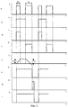
На чертежах представлено: на фиг.1 показана схема предлагаемого устройства; на фиг.2 приведены временные диаграммы, поясняющие работу устройства.The drawings show: figure 1 shows a diagram of the proposed device; figure 2 shows the timing diagrams explaining the operation of the device.
Устройство (фиг.1) содержит делитель частоты входных импульсов 1, интегрирующий операционный усилитель (ОУ) 2, первый ключ 3, первую 4 и вторую 5 логические ячейки 2И, второй 6 и третий 7 ключи, источники отрицательного 8 и положительного 9 постоянных напряжений, первый 10 и второй 11 логические инверторы, первую 12 и вторую 13 логические ячейки 2ИЛИ, формирователь короткого импульса 14, устройство выборки-хранения 15.The device (figure 1) contains a frequency divider of the
Устройство работает следующим образом. Входные импульсы (например, первый длительностью Δt1 и второй длительностью Δt2 (фиг.2,а)) подаются на вход делителя частоты 1, который уменьшает частоту этих импульсов в два раза (фиг.2,б). На входы первой ячейки 2И 4 подаются входные импульсы и сигнал с выхода делителя 1, поэтому на выходе этой ячейки сигнал “1” присутствует в течение действия только первого входного импульса (фиг.2,в). На входы второй ячейки 2И 5 кроме входных импульсов подаются инвертированные (с помощью логического инвертора 10) импульсы с выхода делителя 1, поэтому на выходе этой ячейки сигнал “1” присутствует в течение действия только второго входного импульса (фиг.2,г).The device operates as follows. Input pulses (for example, the first duration Δt 1 and the second duration Δt 2 (Fig.2, a)) are fed to the input of the
Сигналы с ячеек 4 и 5 подаются на входы управления второго 6 и третьего 7 ключей. Ключ 6 подключает к входу интегрирующего ОУ 2 источник отрицательного напряжения 8. Напряжение на выходе интегрирующего ОУ 2 возрастает в течение времени Δt1 по линейному закону до напряжения u1 (фиг.2,д), которое прямо пропорционально длительности импульса:Signals from cells 4 and 5 are fed to the control inputs of the second 6 and third 7 keys. The
![]()
![]()
где k=const - коэффициент пропорциональности, определяемый параметрами интегрирующего ОУ 2.where k = const is the proportionality coefficient determined by the parameters of the integrating OS 2.
В интервале времени Δt2 к входу интегрирующего ОУ 2 (с помощью третьего ключа 7) подключается источник положительного напряжения 9 (напряжения источников 8 и 9 по абсолютной величине должны быть равны). Интегрирование происходит в обратную сторону, причем если бы оно осуществлялось с нулевого уровня, то процесс происходил бы до напряжения u2 (фиг.2д):In the time interval Δt 2 to the input of the integrating op-amp 2 (using the third key 7), a positive voltage source 9 is connected (the voltage of sources 8 and 9 must be equal in absolute value). Integration occurs in the opposite direction, and if it was carried out from zero level, the process would occur up to voltage u 2 (fig.2d):
![]()
![]()
Суммарное напряжение на выходе узла 2 за время (Δt1+Δt2) с учетом (1) и (2) будет равно:The total voltage at the output of node 2 during the time (Δt 1 + Δt 2 ) taking into account (1) and (2) will be equal to:
![]()
![]()
где Δt - разность (по длительности) между двумя соседними импульсами.where Δt is the difference (in duration) between two adjacent pulses.
Входные импульсы (фиг.2,а) и напряжение с выхода делителя 2 (фиг.2,б) подаются на первую логическую ячейку 2ИЛИ 12, поэтому ее выходное напряжение имеет вид, показанный на фиг.2,е. Задним фронтом этого напряжения запускается формирователь короткого импульса 14, вырабатывающий импульс (фиг.2,ж), с помощью которого напряжение (3) запоминается устройством выборки-хранения (УВХ) 15. Оно выполняется инвертирующим с целью изменения знака напряжения (3). Дело в том, что при Δt2>Δt1 это напряжение отрицательно (фиг.2,д). Таким образом, выходное напряжение устройства прямо пропорционально разности длительностей разновременных импульсов:The input pulses (figure 2, a) and the voltage from the output of the divider 2 (figure 2, b) are supplied to the first logical cell 2 OR 12, so its output voltage has the form shown in figure 2, e. The trailing edge of this voltage starts the short-pulse shaper 14, which generates a pulse (Fig. 2, g), with which the voltage (3) is stored by the sampling-storage device (UVX) 15. It is inverted to change the sign of the voltage (3). The fact is that when Δt 2 > Δt 1 this voltage is negative (Fig.2, d). Thus, the output voltage of the device is directly proportional to the difference in the durations of different pulses:
![]()
![]()
Напряжения с выхода ячейки 12 (фиг.2,е) и с выхода формирователя 14 (фиг.2,ж) подаются на вторую логическую ячейку 2ИЛИ 13, выходное напряжение которой показано на фиг.2,з. Оно подается через второй логический инвертор 11 на вход управления первого ключа 3, благодаря чему разряжается конденсатор интегрирующего ОУ 2. С приходом следующего входного импульса (третий импульс на фиг.2,а) цикл повторяется.The voltages from the output of cell 12 (FIG. 2, f) and from the output of the former 14 (FIG. 2, g) are supplied to the second logic cell 2 OR 13, the output voltage of which is shown in FIG. 2, h. It is fed through the second
Формирователь 14 может быть выполнен на основе одновибратора (ждущего мультивибратора), а УВХ - с использованием известных схем на основе ключа, конденсатора и операционных усилителей.Shaper 14 can be made on the basis of a single vibrator (standby multivibrator), and UVX - using well-known circuits based on a key, a capacitor and operational amplifiers.
Таким образом, для заявленного устройства в том виде, как оно охарактеризовано в изложенной ниже формуле изобретения, подтверждена возможность его осуществления с помощью описанных в заявке средств. Также устройство, воплощающее заявленное изобретение при его осуществлении, способно обеспечить достижение усматриваемого заявителем технического результата, заключающегося в сравнении длительностей двух разновременных импульсов, что может использоваться, например, в различных устройствах электроизмерительной техники и автоматики.Thus, for the claimed device in the form as described in the claims below, the possibility of its implementation using the means described in the application is confirmed. Also, a device embodying the claimed invention in its implementation is capable of achieving the achievement of the technical result perceived by the applicant, which consists in comparing the durations of two different pulses that are different, which can be used, for example, in various devices of electrical measuring equipment and automation.
Следовательно, заявленное изобретение соответствует условию “промышленная применимость”.Therefore, the claimed invention meets the condition of “industrial applicability”.
Claims (2)
Priority Applications (1)
| Application Number | Priority Date | Filing Date | Title |
|---|---|---|---|
| RU2002108080/09A RU2231920C2 (en) | 2002-03-29 | 2002-03-29 | Device for comparing length of diverse pulses |
Applications Claiming Priority (1)
| Application Number | Priority Date | Filing Date | Title |
|---|---|---|---|
| RU2002108080/09A RU2231920C2 (en) | 2002-03-29 | 2002-03-29 | Device for comparing length of diverse pulses |
Publications (2)
| Publication Number | Publication Date |
|---|---|
| RU2002108080A RU2002108080A (en) | 2003-09-20 |
| RU2231920C2 true RU2231920C2 (en) | 2004-06-27 |
Family
ID=32845529
Family Applications (1)
| Application Number | Title | Priority Date | Filing Date |
|---|---|---|---|
| RU2002108080/09A RU2231920C2 (en) | 2002-03-29 | 2002-03-29 | Device for comparing length of diverse pulses |
Country Status (1)
| Country | Link |
|---|---|
| RU (1) | RU2231920C2 (en) |
Citations (4)
| Publication number | Priority date | Publication date | Assignee | Title |
|---|---|---|---|---|
| US3790881A (en) * | 1973-03-06 | 1974-02-05 | Us Army | Pulse width selector |
| SU663096A1 (en) * | 1976-12-27 | 1979-05-15 | Предприятие П/Я В-8246 | Pulse duration selector |
| US5912728A (en) * | 1996-03-01 | 1999-06-15 | Commissariat A L'energie Atomique | Device for precisely measuring the duration of a time interval |
| RU2178207C1 (en) * | 2001-01-23 | 2002-01-10 | Ульяновский государственный технический университет | Analog memory device |
-
2002
- 2002-03-29 RU RU2002108080/09A patent/RU2231920C2/en not_active IP Right Cessation
Patent Citations (4)
| Publication number | Priority date | Publication date | Assignee | Title |
|---|---|---|---|---|
| US3790881A (en) * | 1973-03-06 | 1974-02-05 | Us Army | Pulse width selector |
| SU663096A1 (en) * | 1976-12-27 | 1979-05-15 | Предприятие П/Я В-8246 | Pulse duration selector |
| US5912728A (en) * | 1996-03-01 | 1999-06-15 | Commissariat A L'energie Atomique | Device for precisely measuring the duration of a time interval |
| RU2178207C1 (en) * | 2001-01-23 | 2002-01-10 | Ульяновский государственный технический университет | Analog memory device |
Similar Documents
| Publication | Publication Date | Title |
|---|---|---|
| RU2231920C2 (en) | Device for comparing length of diverse pulses | |
| EP0432971A1 (en) | Ultra-sonic motor driving circuit | |
| JPH05111241A (en) | Dc/dc converter | |
| CN101783681A (en) | Frequency Multipliers and Multiplication Methods | |
| RU2097892C1 (en) | Ac relay | |
| EP3393040A1 (en) | Oscillator circuit with comparator delay cancelation | |
| RU2181894C1 (en) | Electricity meter | |
| RU2182361C1 (en) | Ac voltage integrating device | |
| RU2231075C1 (en) | Device for acceleration measurement | |
| RU2256184C1 (en) | Measuring converter for alternating current | |
| SU1296956A2 (en) | Meter of parameters of rectangular pulse sequence | |
| RU46372U1 (en) | AC INTEGRATOR | |
| RU1803980C (en) | Displacement/code converter | |
| GB1587028A (en) | Voltage comparator | |
| SU661559A1 (en) | Multiplying-dividing device | |
| KR970008510B1 (en) | Reset pulse generator | |
| RU2231157C1 (en) | Frequency-difference relay | |
| SU790343A1 (en) | Frequency divider | |
| SU738156A1 (en) | Voltage-to-pulse repetition frequency converter | |
| RU2028628C1 (en) | Method of and device for measuring frequency of low-frequency oscillations | |
| KR970072611A (en) | A plurality of constant voltage source generators | |
| SU790118A1 (en) | Square-wave generator | |
| SU657613A1 (en) | Four-phase pulse generator | |
| SU1347150A1 (en) | Pulse generator | |
| SU569009A1 (en) | Generator of low frequency pulses |
Legal Events
| Date | Code | Title | Description |
|---|---|---|---|
| MM4A | The patent is invalid due to non-payment of fees |
Effective date: 20040330 |