RU2230431C2 - Shipboard emergency radio communication system - Google Patents
Shipboard emergency radio communication system Download PDFInfo
- Publication number
- RU2230431C2 RU2230431C2 RU2002107637/09A RU2002107637A RU2230431C2 RU 2230431 C2 RU2230431 C2 RU 2230431C2 RU 2002107637/09 A RU2002107637/09 A RU 2002107637/09A RU 2002107637 A RU2002107637 A RU 2002107637A RU 2230431 C2 RU2230431 C2 RU 2230431C2
- Authority
- RU
- Russia
- Prior art keywords
- compartments
- compartment
- emergency
- ship
- radio
- Prior art date
Links
Images


Abstract
Description
Изобретение относится к области электрорадиотехники и может быть использовано для организации аварийной радиосвязи на кораблях, судах, подводных аппаратах, т.е. между изолированными, экранированными помещениями (отсеками).The invention relates to the field of electrical engineering and can be used to organize emergency radio communications on ships, ships, underwater vehicles, i.e. between isolated, shielded rooms (compartments).
Одним из основных требований к аварийной системе внутрикорабельной связи (ВКС) является обеспечение устойчивой связи между абонентами, находящимися в герметизированных и практически полностью экранированных помещениях, например отсеках подводных объектов (ПО). При этом предполагается, что на корабле или подводном объекте может возникнуть пожар, затопление отсеков или другая аварийная ситуация.One of the main requirements for an emergency shipborne communication system (VKS) is to ensure stable communication between subscribers located in sealed and almost completely shielded rooms, for example compartments of underwater objects (PO). In this case, it is assumed that a fire, flooding of compartments or other emergency situation may occur on a ship or underwater object.
Известно радиопередающее устройство для связи, используемое в транспортном средстве [патент ФРГ № 3537107, Н 04 В 7/155, 1987].Known radio transmission device for communication used in a vehicle [Germany patent No. 3537107, N 04 7/155, 1987].
Устройство состоит из радиопередатчика, внешней антенны, соединительного фидера, внутренней антенны, усилителя и приемника.The device consists of a radio transmitter, an external antenna, a connecting feeder, an internal antenna, an amplifier, and a receiver.
На транспортном средстве установлена внешняя антенна, принимающая посылаемые радиопередатчиком сигналы. Соединительный фидер антенны введен в транспортное средство, где принятый сигнал усиливается усилителем и посредством внутренней антенны излучается в пределах транспортного средства.The vehicle has an external antenna that receives signals sent by the radio transmitter. An antenna connecting feeder is introduced into the vehicle, where the received signal is amplified by an amplifier and radiated within the vehicle via an internal antenna.
Недостатком этого устройства является невозможность установления гарантированной аварийной связи на кораблях, судах, подводных объектах, где имеется большое количество помещений, отсеков, которые, как правило, находятся в агрессивной внешней среде - воде. При применении такого устройства на корабле не обеспечивается требуемая надежность аварийной связи. Это обусловлено отсутствием в устройстве герметичного перехода ввода фидера и использованием дополнительного усилителя, требующего внешнего питания. Кроме того, в условиях пожара в отсеке фидер устройства является ненадежным элементом, т.к. подвержен выгоранию, что снижает надежность аварийной связи в целом.The disadvantage of this device is the inability to establish guaranteed emergency communications on ships, ships, underwater objects, where there are a large number of rooms, compartments, which, as a rule, are in an aggressive external environment - water. When using such a device on a ship, the required reliability of emergency communications is not provided. This is due to the lack of a feeder input transition in the device and the use of an additional amplifier that requires external power. In addition, in a fire in the compartment, the device feeder is an unreliable element, because it is subject to burnout, which reduces the reliability of emergency communications in general.
Наиболее близким по технической сущности к заявленному объекту является “Система внутрикорабельной аварийной связи” [патент РФ № 2108671, кл. 6 Н 04 В 7/155 1985г.]. Система содержит симметричную направляющую линию, вдоль которой расположены абонентские приборы безбатарейной телефонной связи, малогабаритные приемопередатчики, портативные радиостанции и блоки сопряжения абонентских приборов безбатарейной телефонной связи с приемопередатчиками. Для приема и передачи речевой информации используется физическая цепь двухпроводной линии, по которой передаются электромагнитные волны. Сигналы с приемопередатчика передаются по двухпроводной линии связи в обе стороны и через блок сопряжения поступают на другие приемопередатчики, эти же сигналы проходят через приемопередатчики, усиливаются в блоках сопряжения и излучаются в отсеках корабля. Излучение принимается портативными радиостанциями.Closest to the technical nature of the claimed object is the "System of intra-ship emergency communications" [RF patent No. 2108671, cl. 6 H 04 B 7/155 1985]. The system contains a symmetrical guide line along which the subscriber devices of battery-free telephone communication are located, small-sized transceivers, portable radios and the interface blocks of subscriber devices of battery-free telephone communication with transceivers. The physical circuit of a two-wire line is used to receive and transmit voice information, along which electromagnetic waves are transmitted. Signals from the transceiver are transmitted on a two-wire communication line in both directions and through the interface block are sent to other transceivers, the same signals pass through the transceivers, amplified in the interface blocks and emitted in the compartments of the ship. Radiation is received by portable radios.
Недостатком этой системы является то, что она не обеспечивает гарантированной аварийной связи на корабле вследствие того, что при выгорании любого из отсеков выгорают и проводные линии связи.The disadvantage of this system is that it does not provide guaranteed emergency communication on the ship due to the fact that when any of the compartments burn out, the wired communication lines also burn out.
Одновременно следует указать, что нарушение проходящей через отсеки корабля, подводного объекта электрической магистрали, вызванное пожаром, механическим повреждением, проникновением кислот и т.д., ведет к потере радиосвязи между отсеками корабля, подводного объекта разделенными повреждением.At the same time, it should be pointed out that the violation of the electric line passing through the compartments of the ship, the underwater object caused by fire, mechanical damage, acid penetration, etc., leads to the loss of radio communication between the compartments of the ship and the underwater object separated by damage.
Это обусловлено характером распространения излучения радиостанции, определяемого только наводками на кабельные электрические магистрали ПО или корабля. Нарушение кабельных электрических магистралей в отсеках вследствие пожара наблюдалось на аварийной ПЛ “Комсомолец”.This is due to the nature of the propagation of the radiation from the radio station, determined only by interference on the cable electric trunk of a software or ship. Violation of cable electrical lines in the compartments due to the fire was observed on the emergency submarine Komsomolets.
Таким образом, надежность и эффективность работы существующей системы внутренней аварийной связи недостаточна и находится в зависимости от внешних факторов (состояние кабельных трас).Thus, the reliability and efficiency of the existing internal emergency communication system is insufficient and depends on external factors (the state of cable routes).
Целью настоящего изобретения является повышение надежности и живучести аварийной внутрикорабельной связи.The aim of the present invention is to increase the reliability and survivability of emergency intra-ship communications.
Поставленная цель достигается тем, что в аварийную систему внутрикорабельной связи, состоящую из переносных радиостанций, размещаемых в каждом из отсеков корабля, дополнительно включены металлические полые цилиндры, установленные попарно в межотсечных переборках так, что их торцы находятся в смежных отсеках на расстояниях, кратных ![]()
![]()
Совокупность существенных признаков заявляемого устройства обеспечивает повышение надежности работы системы корабельной внутренней радиосвязи в аварийных условиях.The set of essential features of the claimed device provides increased reliability of the shipboard internal radio communication system in emergency conditions.
На фиг.1 представлена структурная схема системы, где:Figure 1 presents the structural diagram of the system, where:
1 - прочный корпус ПЛ;1 - strong submarine housing;
2 - межотсечные переборки;2 - intersection bulkheads;
3 - переносные радиостанции;3 - portable radio stations;
4 - металлические полые цилиндры;4 - metal hollow cylinders;
5 - герметические крышки из диэлектрика.5 - sealed dielectric covers.
Прочный корпус 1 служит для размещения личного состава и оборудования, межотсечные переборки 2 служат для образования герметизирующихся отсеков и размещения металлических полых цилиндров 4, радиостанции 3 служат для обеспечения передачи и приема информации в радиодиапазонах шкалы электромагнитных волн, металлические полые цилиндры 4 являются резонаторами для рабочих частот радиостанций 3 и служат для канализации электромагнитной энергии в пределах прочного корпуса 1 через переборки 2, герметичные крышки 5 служат для герметизации цилиндров 4 и обеспечивают условия переизлучения электромагнитной энергии при герметизации отсека в целом.The robust housing 1 serves to accommodate personnel and equipment, the inter-compartment bulkheads 2 serve to form pressurized compartments and place metal hollow cylinders 4, radio stations 3 serve to transmit and receive information in the radio ranges of the electromagnetic wave scale, metal hollow cylinders 4 are resonators for operating frequencies radio stations 3 and are used to channel electromagnetic energy within a solid housing 1 through bulkheads 2, sealed covers 5 are used to seal the cylinder ditch 4 and provide conditions for re-emission of electromagnetic energy when sealing the compartment as a whole.
Крепление металлических полых цилиндров 4 с диэлектрическими крышками 5 на межотсечных переборках 2 в более крупном масштабе показано на фиг.2.The fastening of the metal hollow cylinders 4 with dielectric caps 5 on the inter-compartment bulkheads 2 on a larger scale is shown in FIG.
Устройство работает следующим образом.The device operates as follows.
При работе аварийной радиостанции 3 ее антенна возбуждает в пространстве отсека, образованного прочным корпусом 1 и межотсечными переборками 2, электромагнитное поле, представляющее собой комбинацию стоячих электрических и магнитных волн со сложной картиной распространения узлов и пучностей.When the emergency radio station 3 is operating, its antenna excites in the space of the compartment formed by the robust housing 1 and the inter-compartment bulkheads 2 an electromagnetic field, which is a combination of standing electric and magnetic waves with a complex picture of the propagation of nodes and antinodes.
Сложная картина пространственного распределения узлов и пучностей стоячих электрических и магнитных волн определяется неидеальной формой отсека, свойствами материалов, произвольным распределением оборудования и другими факторами.A complex picture of the spatial distribution of nodes and antinodes of standing electric and magnetic waves is determined by the non-ideal compartment shape, material properties, arbitrary distribution of equipment and other factors.
Электромагнитное поле, имеющее частоту, близкую к резонансной для полых металлических цилиндров 4, возбуждает в них направленные волны типа Е, Н или одновременно волны этих типов. Эти волны распространяются вдоль цилиндров 4 и переизлучаются в смежных отсеках.An electromagnetic field having a frequency close to resonant for hollow metal cylinders 4 excites directed waves of the E, H type, or simultaneously waves of these types. These waves propagate along cylinders 4 and are reradiated in adjacent compartments.
Если торец одного из цилиндров 4 располагается в узле электрической или магнитной волны (наихудшее условие возбуждения), то для канализации энергии поля используется другой соседний цилиндр 4, расположенный от первого на расстоянии, кратном нечетному количеству четверти волны (условия пучности стоячей волны, т.е. оптимальных условий возбуждения).If the end face of one of the cylinders 4 is located in the node of an electric or magnetic wave (the worst condition for excitation), then another adjacent cylinder 4 is used to channel the energy of the field, located from the first one at a distance multiple of an odd number of a quarter of the wave (standing wave antinode condition, i.e. optimal excitation conditions).
Таким образом, излучения распространяются из отсека в отсек, испытывая переизлучение на резонаторах, образованных цилиндрами 4 с герметичными крышками 5. Это излучение принимается приемниками остальных радиостанций 3, размещенных в других отсеках. В данной системе радиостанции 3 работают с использованием прямого, а не наведенного излучения. Поэтому дальность аварийной связи будет находиться в пределах всего корабля, а не будет зависеть от расположения радиостанции 3 в пределах отсека, что определяется увеличением напряженности поля и его распределением. Кроме того, по указанной причине система оказывается независимой от нарушения целостности электрической кабельной магистрали, вызванной пожаром или другими причинами. Надежность системы в аварийных условиях обеспечивается применением для герметизации металлических цилиндров 4 высокопрочных термостойких диэлектриков, пожаростойкость которых выше, чем у изделий кабельных корабельных магистралей.Thus, the radiation propagates from compartment to compartment, experiencing re-radiation on the resonators formed by cylinders 4 with sealed covers 5. This radiation is received by the receivers of the remaining radio stations 3 located in other compartments. In this system, radios 3 operate using direct rather than induced radiation. Therefore, the range of emergency communications will be within the entire ship, and will not depend on the location of the radio station 3 within the compartment, which is determined by the increase in field strength and its distribution. In addition, for this reason, the system is independent of the integrity of the electric cable line caused by a fire or other reasons. The reliability of the system in emergency conditions is ensured by the use of 4 high-strength heat-resistant dielectrics for sealing metal cylinders, the fire resistance of which is higher than that of products of cable ship highways.
Параметры элементов системы могут быть оценены следующим образом.The parameters of system elements can be estimated as follows.
Наиболее низкую критическую частоту в волноводе круглого сечения имеет волна типа Н11. При заданной длине волны λ распространение энергии в волноводе круглого сечения возможно, если его радиус большеAn H 11 type wave has the lowest critical frequency in a circular waveguide . For a given wavelength λ, energy can propagate in a circular waveguide if its radius is greater than
![]()
![]()
![]()
![]()
[см. Айзенборг Г.З. и др. Антенны УКВ. Т. I, М.: Связь, 1977].[cm. Eisenborg G.Z. and other VHF antennas. T. I, M .: Communication, 1977].
Учитывая, что, исходя из условий обеспечения прочности, внутренний диаметр цилиндров 4 может составлять 2а=5 см, а длина l=15-20 см, рабочая длина волны λ составит 5-10 см.Given that, based on the conditions for ensuring strength, the inner diameter of the cylinders 4 can be 2a = 5 cm, and the length l = 15-20 cm, the working wavelength λ will be 5-10 cm.
Таким образом, в качестве радиостанции 3 для использования в системе может быть применена переносная корабельная радиостанция Р-622, имеющая указанный диапазон частот и всенаправленную антенну.Thus, as a radio station 3 for use in the system, a portable ship radio station P-622 having a specified frequency range and an omnidirectional antenna can be used.
В качестве материала крышек 5 цилиндрических резонаторов возможно применение специальных стекол, обладающих высокой прочностью, малыми диэлектрическими потерями и температурой плавления 1200-2100°С (синтетический сапфир tпл=2030°, окись магния tпл=2080°). [Крикунов Л.З. Справочник по основам инфракрасной техники. М.: Сов. радио, 1978].As the material of the covers of 5 cylindrical resonators, it is possible to use special glasses with high strength, low dielectric losses and a melting point of 1200-2100 ° C (synthetic sapphire t pl = 2030 °, magnesium oxide t pl = 2080 °). [Krikunov L.Z. Guide to the basics of infrared technology. M .: Sov. Radio, 1978].
Проведем обоснование заявленной системы. Итак, изотропный излучатель, установленный в замкнутом помещении, создает на его стенках поле, энергетическое распределение которого представляет собой сложную интерференционную картину.Let us justify the claimed system. So, an isotropic emitter installed in a closed room creates a field on its walls, the energy distribution of which is a complex interference picture.
В общем случае в предположении, что приходящие в точку приема лучи имеют одинаковые амплитуды и равномерное распределение фаз в пределах 0-2, энергетическое распределение поля будет равномерным. Тогда при увеличении числа описанных ретрансляторов передаваемая в смежные отсеки энергия будет пропорционально увеличиваться. В данном случае попарное размещение ретрансляторов обеспечит усиление эффекта переизлучения. Другим экстремальным случаем будет случай, рассмотренный в заявке, когда интерференционная картина будет представлять собой чередование минимумов и максимумов, отстоящих друг от друга на расстоянии ![]()
![]()
Для подтверждения сказанного рассмотрим интерференцию произвольно взятых двух лучей, представленную на фиг.2.To confirm the above, we consider the interference of arbitrarily taken two rays, presented in figure 2.
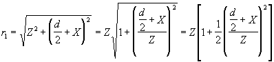
Пусть в помещении, имеющем в плане сегменты а1 а2 а3 a4 (где a1 а2=d=а3 a4 - ширина помещения и a1 а3=z - длина), интерферируют два луча, исходящих из точек а1 а2, причем картина имеет максимум в точке 0.Let in a room having segments a 1 a 2 a 3 a 4 in plan (where a 1 a 2 = d = a 3 a 4 is the width of the room and a 1 a 3 = z is the length), two rays emanating from the points and 1 a 2 , and the picture has a maximum at
Точка 0 симметрична относительно точек a1 а2 и a3 a4.
Заметим также, что точки а1 а2 могут рассматриваться не только как крайние точки отсека, но и как две любые точки, произвольно выбранные в пространстве симметрично относительно оси 001.We also note that the points a 1 and 2 can be considered not only as the extreme points of the compartment, but also as any two points arbitrarily selected in space symmetrically with respect to the axis 00 1 .
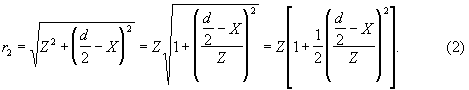
Определим расстояние от точки 0 до ближайшего минимума Х интерференционной картины. Два луча, исходящих из точек а1 а2, будут иметь длину хода лучей r1 и r2. Результат взаимодействия лучей A(t) в точке Х можно записать какWe determine the distance from
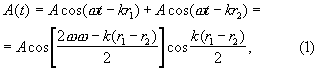
где А - амплитуда, ω - частота, ![]()
![]()
В соответствии с обозначениями на фиг.3 длина хода лучей определяется:In accordance with the notation of figure 3, the length of the rays is determined:
Рассмотрим ход лучей:Consider the course of the rays:

Таким образом, функция A(t) имеет минимум, когда:Thus, the function A (t) has a minimum when:
![]()
![]()
![]()
![]()
откудаwhere from
![]()
![]()
Обычно Z=1,5-2d, поэтому в реальном случае минимум картины, создаваемый большинством отраженных лучей, будет отстоять от максимума на расстояние ![]()
![]()
Эффективность работы системы в условиях пожара будет определяться потерями на распространение поля в плазме, то есть величиной диэлектрической проницаемости. Как указано в В.А. Гинзбург. “Распространение радиоволны в плазме”. М.: 1969 г.The efficiency of the system in a fire will be determined by the propagation loss of the field in the plasma, that is, the value of the dielectric constant. As indicated in B.A. Ginzburg. “Plasma Radio Wave Propagation.” M .: 1969
![]()
![]()
где fпл=107 Гц - частота плазмы.where f PL = 10 7 Hz is the plasma frequency.
Так как система использует для работы сантиметровый частотный диапазон, то ![]()
![]()
При полном затоплении отсека работоспособность системы в целом несколько снизится, вследствие того, что на участке затопленного отсека ведущую роль при ретрансляции сигнала будут играть кабельные трассы, которые в этом случае сохранятся. При частичном затоплении отсека, когда ретрансляторы не закрыты водой (экипаж сохраняет работоспособность), предлагаемая система работает эффективно.When the compartment is completely flooded, the overall system performance will slightly decrease, due to the fact that cable routes will play a leading role in the relayed section of the signal, which will remain in this case. With partial flooding of the compartment, when the transponders are not covered by water (the crew remains operational), the proposed system works efficiently.
В системе предполагается возбуждать резонаторы ненаправленным излучением радиостанции типа Р-622, следовательно, мощность возбуждения резонатора будет невелика, противоположный конец резонатора также генерирует ненаправленные излучения, таким образом, через 1-2 отсека излучение будет столь мало, что никакая радиостанция его не воспримет.The system is supposed to excite resonators with non-directional radiation of a P-622 type radio station, therefore, the excitation power of the resonator will be small, the opposite end of the resonator will also generate non-directional radiation, so after 1-2 compartments the radiation will be so small that no radio station will perceive it.
Это замечание справедливо для условий свободного пространства или ограниченного полупространства.This remark is valid for conditions of free space or bounded half-space.
Однако в условиях замкнутого объема, ограниченного проводящей средой (случай загерметизированного отсека подводного объекта или помещения НК), независимо от типа излучателя (штырь, диполь и др.), вся испускаемая им энергия будет заключена в пределах указанного пространства.However, in a confined space limited by a conducting medium (the case of a sealed compartment of an underwater object or a spacecraft), regardless of the type of emitter (pin, dipole, etc.), all the energy emitted by it will be enclosed within the specified space.
При этом, если имеется согласованное с длиной волны и оптимально размещенное устройство вывода (в данном случае предлагается резонатор), в идеальном случае вся излученная энергия будет передана через это устройство.Moreover, if there is an output device that is consistent with the wavelength and optimally placed (in this case, a resonator is proposed), in the ideal case, all the radiated energy will be transmitted through this device.
В данном случае излучение радиостанции будет распространяться во всех направлениях в пределах диаграммы направленности, испытывая на каждом из направлений многократные отражения на экранирующей поверхности отсека и создавая на ней сложную интерференционную картину с чередованием максимумов и минимумов.In this case, the radiation of the radio station will propagate in all directions within the radiation pattern, experiencing multiple reflections on each of the directions on the screening surface of the compartment and creating a complex interference pattern on it with alternating maxima and minima.
Если поместить в пучности такой картины согласованный резонатор, то он и будет являться единственным источником “утечки” всей энергии.If you place a matched resonator in the antinodes of such a picture, then it will be the only source of “leakage” of all energy.
При этом в его возбуждение будут вносить вклад теоретически все пучки энергии, излучаемые антенной по различным направлениям, а не только пучки, падающие непосредственно на торец волновода. Таким образом, в идеальном случае резонатор теоретически будет возбуждаться всей энергией электромагнитного поля, излученной антенной.In this case, theoretically, all the energy beams emitted by the antenna in various directions, and not only the beams incident directly on the end of the waveguide, will contribute to its excitation. Thus, in the ideal case, the resonator will theoretically be excited by all the energy of the electromagnetic field emitted by the antenna.
В реальных условиях на каждом из направлений излучения будут иметь место потери, определяемые потерями в материале в местах отражений на границе “воздух-металл”. Тем не менее, несмотря на потери, энергия возбуждения резонатора будет больше энергии, определяемой лучами, падающими непосредственно на его торец, что позволит получить дальность связи большую, чем через 1-2 отсека. Однако даже в случае возбуждения резонатора только прямым излучением (наихудший случай) энергетические соотношения на трассе распространения обеспечат дальность связи значительно большую, чем два отсека.Under real conditions, in each direction of radiation there will be losses determined by the losses in the material at the places of reflections at the air-metal interface. Nevertheless, in spite of the losses, the excitation energy of the resonator will be greater than the energy determined by the rays incident directly on its end, which will make it possible to obtain a communication range greater than 1-2 compartments. However, even in the case of excitation of the resonator by direct radiation only (the worst case), the energy relations on the propagation path will provide a communication range much greater than two compartments.
Для оценки энергетических соотношений аварийной связи рассмотрим модель трассы. Модель представлена на фигуре 3.To assess the energy ratios of emergency communications, we consider the route model. The model is presented in figure 3.
В модели предполагается, что стенки отсека покрыты поглощающим покрытием. В качестве излучателя в модели выбран диполь (всенаправленная антенна радиостанции образована двумя скрещенными диполями), в качестве приемной антенны - также диполь, имеющий косинусную диаграмму направленности одного лепестка, как и торец резонатора.The model assumes that the compartment walls are coated with an absorbent coating. In the model, a dipole was chosen as the emitter (the omnidirectional antenna of the radio station is formed by two crossed dipoles), as the receiving antenna, also a dipole having a cosine radiation pattern of one lobe, as well as the end face of the resonator.
При расчетах используем технические характеристики радиостанции Р-622 [Катанович А.А. Судовая светосигнальная связь. СПб.: Судостроение, 2002]In the calculations we use the technical characteristics of the radio station R-622 [A. Katanovich Ship light-signal communication. St. Petersburg: Shipbuilding, 2002]
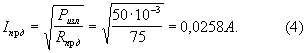
- мощность передатчика 50 мВт;- transmitter power 50 mW;
- чувствительность 5·10-15 Вт;- sensitivity 5 · 10 -15 W;
- дальность связи:- communication range:
на узконаправленные антенны - до 20 км;for narrowly directed antennas - up to 20 km;
на всенаправленные антенны - до 3 км.omnidirectional antennas - up to 3 km.
Сопротивление излучения полуволнового вибратора Rпрд=Rпp=75 Ом.The radiation resistance of a half-wave vibrator R prd = R pp = 75 Ohms.
Тогда максимальный ток в передающей антеннеThen the maximum current in the transmitting antenna
![]()
![]()
Максимальное Емгн прд мгновенное значение напряженности поля, создаваемое передающей антенной на расстоянии r=10 м (длина отсека), определяется [А.С. Дрибкин. Антенно-фидерные устройства. М.: Сов. радио, 1961], какThe maximum E mgn prd instantaneous value of the field strength created by the transmitting antenna at a distance of r = 10 m (compartment length) is determined [A.S. Dribkin. Antenna feeder devices. M .: Sov. radio, 1961] how
![]()
![]()
где ![]()
![]()
θ - угол направления на точку измерения (приема);θ is the angle of direction to the measuring point (reception);
r - расстояние до точки измерения;r is the distance to the measurement point;
l - длина элементарного диполя.l is the length of the elementary dipole.
![]()
![]()
Из этого же источника известно, что ЭДО, возбуждаемую в приемной антенне, можно определить из соотношенияFrom the same source it is known that the EDO excited in the receiving antenna can be determined from the relation
![]()
![]()
где σ - коэффициент усиления антенны (для диполя σ=3,28);where σ is the antenna gain (for the dipole, σ = 3.28);
F(φ,θ) - диаграмма направленности, зависящая от пространственных углов ориентации приемной антенны на источник излучения (может быть принята равной единице вследствие ограниченности по угловому перемещению передатчика и приемника).F (φ, θ) is the radiation pattern depending on the spatial angles of orientation of the receiving antenna to the radiation source (can be taken equal to unity due to the limited angular displacement of the transmitter and receiver).
ОткудаWhere from
![]()
![]()
Коэффициент передачи по мощности для двух смежных отсеков составит:The power transmission coefficient for two adjacent compartments will be:
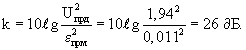
Энергетический запас “приемник-передатчик” составляетThe energy reserve of the “transmitter-receiver” is
![]()
![]()
Таким образом, количество отсеков, обслуживаемых одной радиостанцией в одном направлении:Thus, the number of compartments served by one radio station in one direction:
![]()
![]()
При размещении управляющей радиостанции в середине подводного объекта, общее количество отсеков которой не превышает 10, можно при использовании предлагаемой системы осуществлять связь в пределах всего подводного объекта.When placing the control radio station in the middle of the underwater object, the total number of compartments of which does not exceed 10, you can use the proposed system to communicate within the entire underwater object.
Приведенный расчет проводился для наихудших условий распространения радиоволн. Однако с учетом дополнительного вклада в возбуждение резонаторов отраженных пучков имеется возможность прямой радиосвязи через все отсеки подводного объекта.The above calculation was performed for the worst propagation conditions of radio waves. However, taking into account the additional contribution of reflected beams to the excitation of resonators, there is the possibility of direct radio communication through all compartments of the underwater object.
Для наилучших условий (идеальное распространение энергии без потерь на стенках отсека и оптимальное возбуждение резонатора) расчет не приводится, т.к. длина подводного объекта до 150 м, что значительно меньше дальности действия радиостанции - 3 км.For the best conditions (ideal energy distribution without loss on the compartment walls and optimal resonator excitation), no calculation is given, because the length of the underwater object is up to 150 m, which is significantly less than the range of the radio station - 3 km.
Можно заметить, что, отражаясь от переборок, волны, доходящие до резонаторов, будут испытывать интерференцию, что приведет к случайным замираниям сигнала на входах и, следовательно, выходам резонаторов.It can be noted that, reflected from the bulkheads, waves reaching the resonators will experience interference, which will lead to random fading of the signal at the inputs and, therefore, the outputs of the resonators.
Действительно, излучение антенны создает на стенках отсека сложную интерференционную картину поля с чередованием максимумов и минимумов на расстояниях, кратных ![]()
![]()
Таким образом, для одного из резонаторов условия возбуждения будут близкими к оптимальным.Thus, for one of the resonators, the excitation conditions will be close to optimal.
Тактико-экономическое обоснование заключается в следующем:The feasibility study is as follows:
1. Обеспечивается устойчивая работа системы в аварийных условиях при нарушениях целостности кабельных электрических магистралей, вызванных пожаром и механическими повреждениями или другими причинами.1. Provides stable operation of the system in emergency conditions in case of violation of the integrity of the cable electrical lines caused by fire and mechanical damage or other reasons.
2. Обеспечивается безретрансляционный прием сигналов радиостанций во всех отсеках корабля одновременно при произвольном расположении радиостанции внутри каждого из отсеков.2. A non-relaying reception of signals from radio stations in all compartments of the ship is provided simultaneously with an arbitrary arrangement of the radio station inside each of the compartments.
Claims (1)
Priority Applications (1)
| Application Number | Priority Date | Filing Date | Title |
|---|---|---|---|
| RU2002107637/09A RU2230431C2 (en) | 2002-03-25 | 2002-03-25 | Shipboard emergency radio communication system |
Applications Claiming Priority (1)
| Application Number | Priority Date | Filing Date | Title |
|---|---|---|---|
| RU2002107637/09A RU2230431C2 (en) | 2002-03-25 | 2002-03-25 | Shipboard emergency radio communication system |
Publications (2)
| Publication Number | Publication Date |
|---|---|
| RU2002107637A RU2002107637A (en) | 2003-09-20 |
| RU2230431C2 true RU2230431C2 (en) | 2004-06-10 |
Family
ID=32845522
Family Applications (1)
| Application Number | Title | Priority Date | Filing Date |
|---|---|---|---|
| RU2002107637/09A RU2230431C2 (en) | 2002-03-25 | 2002-03-25 | Shipboard emergency radio communication system |
Country Status (1)
| Country | Link |
|---|---|
| RU (1) | RU2230431C2 (en) |
Cited By (2)
| Publication number | Priority date | Publication date | Assignee | Title |
|---|---|---|---|---|
| RU2446569C1 (en) * | 2010-12-21 | 2012-03-27 | Открытое акционерное общество "Концерн "Созвездие" | Emergency system of radio interior communications |
| RU2756063C1 (en) * | 2020-05-28 | 2021-09-27 | Федеральное государственное казенное военное образовательное учреждение высшего образования "Военный учебно-научный центр Военно-Морского Флота "Военно-морская академия имени Адмирала флота Советского Союза Н.Г. Кузнецова" | Tropospheric radio station of ship |
-
2002
- 2002-03-25 RU RU2002107637/09A patent/RU2230431C2/en not_active IP Right Cessation
Non-Patent Citations (1)
| Title |
|---|
| ВОСКРЕСЕНСКИЙ Д.И. Антенны и устройства СВЧ. - М.: Радио и связь, 1981, с.76. * |
Cited By (2)
| Publication number | Priority date | Publication date | Assignee | Title |
|---|---|---|---|---|
| RU2446569C1 (en) * | 2010-12-21 | 2012-03-27 | Открытое акционерное общество "Концерн "Созвездие" | Emergency system of radio interior communications |
| RU2756063C1 (en) * | 2020-05-28 | 2021-09-27 | Федеральное государственное казенное военное образовательное учреждение высшего образования "Военный учебно-научный центр Военно-Морского Флота "Военно-морская академия имени Адмирала флота Советского Союза Н.Г. Кузнецова" | Tropospheric radio station of ship |
Similar Documents
| Publication | Publication Date | Title |
|---|---|---|
| Domingo | Magnetic induction for underwater wireless communication networks | |
| US7826794B2 (en) | Distributed underwater electromagnetic communication system | |
| WO2015159808A1 (en) | Radio communication device and radio communication system | |
| Molina-Garcia-Pardo et al. | On the possibility of interpreting field variations and polarization in arched tunnels using a model for propagation in rectangular or circular tunnels | |
| CN103392263B (en) | A kind of antenna system | |
| US20020128052A1 (en) | Long-range, full-duplex, modulated-reflector cell phone for voice/data trasmission | |
| US7982679B2 (en) | Transmission of underwater electromagnetic radiation through the seabed | |
| WO2023283352A1 (en) | Multipath repeater systems | |
| WO2011145515A1 (en) | Magnetic wave antenna and magnetic wave communication device | |
| CN112993556A (en) | Small low-frequency transmitting-receiving integrated antenna and application | |
| Hou et al. | Capacity of 4-by-4 MIMO channel using one composite leaky coaxial cable with user position information | |
| US5189432A (en) | Radiating antenna cable apparatus | |
| US6657516B1 (en) | Wideband TE11 mode coaxial turnstile junction | |
| RU2230431C2 (en) | Shipboard emergency radio communication system | |
| Aboderin | Antenna design for underwater applications | |
| Merrill | Some early historical aspects of project sanguine | |
| CN104092024A (en) | Direction backtracking system based on corner reflector antenna array | |
| Nishikawa et al. | Two dimensional position detection method using bi-directional leaky coaxial cable based on TDOA | |
| Manteghi | An electrically small antenna for underwater applications | |
| US3058106A (en) | Space satellites for use as radio system repeaters | |
| US3680133A (en) | Subsurface traveling wave antenna | |
| US6218994B1 (en) | Small antennas for communication over sea ice | |
| RU2260249C2 (en) | Deep-water cable communication system for submarines | |
| RU2446569C1 (en) | Emergency system of radio interior communications | |
| US20240089743A1 (en) | Apparatus, methods and systems for improving coverage of wireless communication networks |
Legal Events
| Date | Code | Title | Description |
|---|---|---|---|
| MM4A | The patent is invalid due to non-payment of fees |
Effective date: 20050326 |