RU2225603C2 - Method and gear for dynamic balancing of gimbal drive - Google Patents
Method and gear for dynamic balancing of gimbal drive Download PDFInfo
- Publication number
- RU2225603C2 RU2225603C2 RU2002112161/11A RU2002112161A RU2225603C2 RU 2225603 C2 RU2225603 C2 RU 2225603C2 RU 2002112161/11 A RU2002112161/11 A RU 2002112161/11A RU 2002112161 A RU2002112161 A RU 2002112161A RU 2225603 C2 RU2225603 C2 RU 2225603C2
- Authority
- RU
- Russia
- Prior art keywords
- balancing
- cardan
- rotation
- imbalance
- supports
- Prior art date
Links
Images
Landscapes
- Testing Of Balance (AREA)
Abstract
Description
1. Способ по п.1 формулы. 1. The method according to claim 1 of the formula.
Изобретение относится к способам уравновешивания роторов и может быть использовано для балансировки карданных передач. The invention relates to methods for balancing rotors and can be used to balance cardan gears.
Известен способ уравновешивания гибких роторов по а.с. 317937 G 01 M 1/24, заключающийся в том, что на ротор устанавливают систему известных грузов, дисбаланс которых пропорционален ординатам кривой прогибов ротора с исходной неуравновешенностью. Недостатком этого способа является необходимость в использовании системы пробных грузов, которые подбираются в соответствии с измеренной кривой прогиба ротора, что накладывает ограничения, связанные со сложной неоднократной обработкой пространственных взаимосвязанных кривых и непростыми математическими преобразованиями при каждом пробном измерении. A known method of balancing flexible rotors by AS 317937 G 01 M 1/24, consisting in the fact that a system of known loads is installed on the rotor, the imbalance of which is proportional to the ordinates of the curve of the rotor deflections with the initial imbalance. The disadvantage of this method is the need to use a system of test weights, which are selected in accordance with the measured curve of the deflection of the rotor, which imposes restrictions associated with the complex repeated processing of spatial interconnected curves and difficult mathematical transformations for each test measurement.
Известен способ балансировки роторов по а.с. 1464093, G 01 M 1/24, заключающийся в использовании опор с регулируемой жесткостью, которая подбирается при одновременном подборе величины снимаемой балансировочным инструментом массы. Недостатком этого способа является сложная система балансировки, многоступенчатость повторяющихся операций, которая ограничивают применение этого способа только специальными устройствами с магнитными подвесами. A known method of balancing rotors by AS 1464093, G 01 M 1/24, which consists in the use of supports with adjustable stiffness, which is selected while simultaneously selecting the mass removed by the balancing tool. The disadvantage of this method is the complex balancing system, multi-stage repetitive operations, which limit the application of this method only to special devices with magnetic suspensions.
Известен также способ уравновешивания роторов по а.с. 386300, G 01 M 1/24, наиболее близкий по технической сущности, принятый за прототип, заключающийся в том, что по найденным значениям величины и угловой координаты неуравновешенности определяют величины и направления смещения главной центральной оси инерции ротора по отношению к оси вращения в плоскостях центров масс отдельных участков ротора и устанавливают в этих плоскостях балансирующие грузы. Недостатком этого способа является то, что способ решает задачу определения группы дискретных грузов, предназначенных для компенсации неуравновешенности, возникшей после изменения формы ротора, на определенной скорости вращения. После снижения скорости дисбаланс вновь увеличится и ничем не будет скомпенсирован. There is also known a method of balancing rotors by AS 386300, G 01 M 1/24, the closest in technical essence, adopted as a prototype, which consists in the fact that the values and the directions of displacement of the main central axis of inertia of the rotor relative to the axis of rotation in the planes of the centers are determined from the found values of the magnitude and angular coordinate of the imbalance masses of individual sections of the rotor and set balancing weights in these planes. The disadvantage of this method is that the method solves the problem of determining a group of discrete weights designed to compensate for the imbalance that occurred after changing the shape of the rotor at a certain rotation speed. After reducing the speed, the imbalance will increase again and will not be compensated for by anything.
Технической задачей заявленного изобретения является повышение качества уравновешивания карданных передач за счет поэтапной компенсации дисбаланса отдельных узлов: предварительно - на валу, затем - на карданах и окончательно - на всей карданной передаче. The technical task of the claimed invention is to improve the quality of balancing the driveshafts due to the phased compensation of the imbalance of individual nodes: first on the shaft, then on the driveshafts and finally on the entire driveshaft.
Поставленная задача решается следующим образом. The problem is solved as follows.
На балансировочном станке определяют величину и угловую координату неуравновешенности, по найденным значениям величины и угловой координаты неуравновешенности одним из известных способов уменьшают дисбаланс, устанавливая балансировочные грузы в двух плоскостях вала карданной передачи, затем воздействием на вибровоспринимающие опоры смещают карданы один относительно другого, обеспечив параллельность осей вращения внешней части одного кардана относительно внешней части другого, и после определения величин и углов появившейся неуравновешенности уменьшают дисбаланс, устанавливая грузы в плоскостях, проходящих через крестовины карданов, и, жестко зафиксировав от колебаний вибровоспринимающие опоры, проводят приработку карданной передачи, после чего убирают фиксацию опор и смещение осей карданов и вала, и при вращении окончательно устраняют дисбаланс, устанавливая балансировочные грузы в двух плоскостях на вал карданной передачи. On the balancing machine, the magnitude and the angular coordinate of the imbalance are determined, using the known values of the magnitude and the angular coordinate of the imbalance, one of the known methods reduces the imbalance by setting the balancing weights in the two planes of the cardan shaft, then, by acting on the vibration-absorbing supports, the cardans are displaced relative to each other, ensuring the rotation axes are parallel the outer part of one cardan relative to the outer part of the other, and after determining the values and angles of the appearing self-balancing reduce unbalance by setting loads in the planes passing through the universal joints of the driveshafts and rigidly fixing vibration-absorbing supports from vibrations, run in the drive-in gear, then fix the supports and the axes of the driveshafts and the shaft, and during rotation they completely eliminate the imbalance by setting balancing weights in two planes on the cardan shaft.
Отличительными признаками в заявленном техническом решении являются:
Воздействием на вибровоспринимающие опоры смещают карданы один относительно другого, обеспечив параллельность осей вращения внешней части одного кардана относительно внешней части другого, и после определения величин и углов появившейся неуравновешенности уменьшают дисбаланс, устанавливая грузы в плоскостях, проходящих через крестовины карданов, и, жестко зафиксировав от колебаний вибровоспринимающие опоры, проводят приработку карданной передачи, после чего убирают фиксацию опор и смещение осей карданов и вала, и при вращении окончательно устраняют дисбаланс, устанавливая балансировочные грузы в двух плоскостях на вал карданной передачи.Distinctive features in the claimed technical solution are:
By acting on vibration-absorbing supports, the cardans are displaced relative to one another, ensuring that the axes of rotation of the outer part of one cardan are parallel to the external part of the other, and after determining the magnitudes and angles of the resulting imbalance, they reduce the imbalance by setting weights in the planes passing through the universal joints of the cardan and rigidly fixing it from vibrations vibration-absorbing bearings, run in the driveshaft, then remove the fixation of the supports and the displacement of the axles of the cardan and shaft, and when the windows rotate atelno eliminate the imbalance, balancing loads in setting the two planes on the shaft driveline.
Такая последовательность действий позволяет выявить неуравновешенность и снизить дисбаланс, возникающий непосредственно в карданном узле при изменившихся углах. Приработка в течение заданного времени повышает равномерность вращения, что улучшает качество уравновешивания карданной передачи. This sequence of actions allows you to identify imbalance and reduce the imbalance that occurs directly in the gimbal node with changing angles. Running in for a predetermined time increases the uniformity of rotation, which improves the quality of balancing the cardan gear.
Из изученной патентной и научно-технической литературы автору неизвестно техническое решение с перечисленной совокупностью признаков, что дало основание сделать вывод о соответствии способа критериям изобретения. From the studied patent and scientific and technical literature, the author does not know the technical solution with the listed set of features, which gave reason to conclude that the method meets the criteria of the invention.
На фиг.1 представлена схема смещения осей вращения карданов относительно первоначальной оси вращения вала, где приняты следующие обозначения:
1, 2 - вибровоспринимающие опоры,
3 - первоначальная ось вращения вала карданной передачи,
4 - вал карданной передачи,
5, 6 - оси вращения карданов,
7, 8 - карданы,
9, 10 - плоскости крестовин карданов,
11 - фиксация вибровоспринимающих опор.Figure 1 presents a diagram of the displacement of the axes of rotation of the cardan relative to the original axis of rotation of the shaft, where the following notation:
1, 2 - vibration-absorbing supports,
3 - the initial axis of rotation of the driveshaft shaft,
4 - cardan shaft,
5, 6 - axis of rotation of the cardan,
7, 8 - cardans,
9, 10 - plane of the universal joints,
11 - fixing vibration-absorbing supports.
Способ реализуется следующим образом. The method is implemented as follows.
Балансируемую карданную передачу устанавливают в вибровоспринимающие опоры 1 и 2, приводят во вращение вокруг оси вращения 3. Известным способом определяют параметры неуравновешенности и балансируют, устанавливая грузы в двух плоскостях на вал 4. Затем, в частности, перемещением опоры 1 в одну и опоры 2 в другую или их поворотом в противоположные стороны, сохраняя параллельность осей вращения 5 и 6 карданов 7 и 8, изменяют ось вращения вала 4 относительно первоначальной оси 3 и фиксируют положение опор. Появившуюся после этого неуравновешенность, после определения ее параметров по величинам и углам, уменьшают, устанавливая балансировочные грузы в плоскостях 9, 10 крестовин карданов 7, 8. После этого жестко фиксируют фиксацией 11 вибровоспринимающие опоры 1 и 2 от восприятия колебаний в этом положении, исключая тем самым воздействие на них вибраций карданной передачи, проводят ее приработку в течение заданного времени. После окончания приработки убирают фиксацию 11 вибровоспринимающих опор, восстанавливают чувствительность к вибрациям и возвращают всю систему в исходное положение, то есть в положение, когда оси вращения 5, 6 совпадают с осью 3. В данном положении по результатам определения параметров неуравновешенности окончательно устраняют дисбаланс, устанавливая балансировочные грузы в двух плоскостях на вал 4 карданной передачи. The balanced cardan drive is installed in vibration-absorbing
Использование заявленного изобретения позволяет повысить качество уравновешивания карданных передач. The use of the claimed invention allows to improve the quality of balancing cardan gears.
2. Устройство по п.1: Стенд динамической балансировки карданных передач относится к области машиностроения и может быть использован для определения и устранения неуравновешенности изделий. 2. The device according to claim 1: The stand for the dynamic balancing of cardan gears relates to the field of mechanical engineering and can be used to determine and eliminate imbalance of products.
Известна механическая система балансировочного станка по а.с. 1619084, G 01 M 1/02, содержащая основание и размещенную на нем платформу, на одной поверхности которой закреплены опоры для ротора, а на другой - шаровые опоры. Узел разделения плоскостей коррекции содержит узел фиксации плоскостей коррекции, включающий две пары опор, закрепленных на платформе, ограничительные стойки и электромагниты, закрепленные на основании. Known mechanical system of a balancing machine for AS 1619084, G 01 M 1/02, containing a base and a platform placed on it, on one surface of which are mounted supports for the rotor, and on the other - ball bearings. The node for separation of the correction planes contains a node for fixing the correction planes, including two pairs of supports fixed on the platform, restrictive racks and electromagnets fixed on the base.
Недостатком этого устройства является то, что опоры для ротора закреплены на общем основании и балансировка ротора осуществляется как единого, не меняющего своей геометрии тела. The disadvantage of this device is that the supports for the rotor are fixed on a common basis and the balancing of the rotor is carried out as a single body that does not change its geometry.
Известно устройство для балансировки роторов по а.с. 564556, G 01 M 1/24, состоящее из станины, торсионного вала, зажимной опоры, перемещающейся с помощью ходового винта. Торсионный вал опирается на подшипниковую опору, свободный его конец снабжен полумуфтой для соединения с балансируемым ротором, который установлен на виброчувствительные опоры. A device for balancing rotors by AS 564556, G 01 M 1/24, consisting of a bed, a torsion shaft, a clamping support moving with a spindle. The torsion shaft rests on a bearing support, its free end is equipped with a coupling half for connecting to a balanced rotor, which is mounted on vibration-sensitive bearings.
Недостатком устройства является малая величина углов колебаний, которые создаются только с одного конца ротора, из-за чего моменты инерции на разных концах ротора имеют разную величину. The disadvantage of this device is the small value of the angles of oscillation that are created only from one end of the rotor, because of which the moments of inertia at different ends of the rotor have different values.
Известно устройство: стенд для обкатки карданных валов по а.с. 1580193, G 01 M 1/24, наиболее близкое по технической сущности и выбранное за прототип. A device is known: a stand for running in cardan shafts by a.s. 1580193, G 01 M 1/24, the closest in technical essence and selected for the prototype.
Стенд содержит основание, размещенную на нем с возможностью перемещений плиту с приводом и размещенные на основании распределительный редуктор с входным валом, выполненным с тормозом, привод вращения карданных передач, связанный с входным валом, и виброизмерительные опоры. На плите размещены виброизмерительные опоры и замыкающий два балансируемых карданных вала редуктор. Недостатком этого решения является сложность конструкции. The stand contains a base, a plate with a drive placed on it with the possibility of movement and a distribution gear placed on the base with an input shaft made with a brake, cardan gear rotation drive connected to the input shaft, and vibration measuring bearings. Vibration mounts and a reducer closing two balancing cardan shafts are placed on the plate. The disadvantage of this solution is the design complexity.
Технической задачей заявленного изобретения является упрощение конструкции балансировочного станка, реализующего совмещение операций приработки и балансировки последовательно карданов и затем всей карданной передачи. The technical task of the claimed invention is to simplify the design of a balancing machine that implements a combination of running-in and balancing sequentially universal joints and then the entire universal joint transmission.
Поставленная задача решается следующим образом. The problem is solved as follows.
Стенд динамической балансировки карданных передач содержит основание, размещенную на нем с возможностью перемещения по его поверхности плиту, виброизмерительные опоры для размещения карданных передач и привод вращения, каждая виброизмерительная опора содержит люльку из двух частей, причем нижняя, подвешенная на пружинах, содержит симметрично расположенную вертикальную ось, на которой с возможностью поворота установлена верхняя часть, с закрепленным на ней шпинделем для подсоединения и вращения карданной передачи, привод вращения установлен на плите с возможностью углового перемещения, соответствующего углу поворота приводного шпинделя вокруг оси люльки таким образом, чтобы их оси вращения находились в одной вертикальной плоскости, виброизмерительные опоры содержат устройство блокировки колебаний и фиксации углового положения люльки и установлены с возможностью перемещения вдоль основания. The dynamic balancing stand for cardan gears contains a base placed on it with the possibility of moving a plate along its surface, vibration measuring supports for placing cardan gears and a rotation drive, each vibration measuring support contains a cradle in two parts, and the lower one, suspended on springs, contains a symmetrically located vertical axis , on which the upper part is rotatably mounted, with a spindle mounted on it for connecting and rotating the cardan gear, mounted on a plate with the possibility of angular movement corresponding to the angle of rotation of the drive spindle around the cradle axis so that their axis of rotation are in the same vertical plane, vibration measuring supports contain a vibration blocking device and fix the angular position of the cradle and are mounted for movement along the base.
Отличительными признаками в заявленном техническом решении являются:
Каждая виброизмерительная опора содержит люльку из двух частей, причем подвешенная на пружинах нижняя часть содержит симметрично расположенную вертикальную ось, на которой с возможностью поворота установлена верхняя часть, с закрепленным на ней шпинделем для подсоединения и вращения карданной передачи, а привод вращения установлен на плите с возможностью углового перемещения, соответствующего углу поворота приводного шпинделя вокруг оси люльки таким образом, чтобы их оси вращения находились в одной вертикальной плоскости, виброизмерительные опоры содержат устройство блокировки колебаний и фиксации углового положения люльки и установлены с возможностью перемещения вдоль основания.Distinctive features in the claimed technical solution are:
Each vibration-measuring support contains a cradle in two parts, the lower part suspended on the springs contains a symmetrically located vertical axis, on which the upper part is rotatably mounted, with a spindle mounted on it for connecting and rotating the cardan gear, and the rotation drive is mounted on the plate with the possibility of angular displacement corresponding to the angle of rotation of the drive spindle around the cradle axis so that their axis of rotation are in the same vertical plane, vibration The support legs contain a device for blocking vibrations and fixing the angular position of the cradle and are mounted with the possibility of movement along the base.
Такое решение позволяет создать угловое смещение в системе опор, карданов и вала карданной передачи и обеспечить режим балансировки, приближенный к реальным условиям работы передач. This solution allows you to create an angular displacement in the system of supports, cardans and cardan shaft and provide a balancing mode close to the actual operating conditions of the gears.
Из изученной патентной и научно-технической литературы автору неизвестно техническое решение с перечисленной совокупностью признаков, что дает основание сделать вывод о соответствии заявленного устройства критериям изобретения. From the studied patent and scientific and technical literature, the author does not know the technical solution with the listed set of features, which gives reason to conclude that the claimed device meets the criteria of the invention.
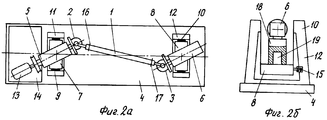
На фиг. 2а, 2б представлен схематический чертеж стенда, на фиг.2а - вид сверху (датчики не показаны), на фиг.2б - вид сбоку со стороны правой опоры. Устройство блокировки колебаний и фиксации угла не показано. На фиг.2а, 2б приняты следующие обозначения:
1 - карданная передача,
2, 3 - карданы,
4 - основание,
5 - шпиндель приводной,
6 - шпиндель,
7, 8 - люльки,
9, 10 - пружины,
11, 12 - опоры,
13 - привод,
14 - плита,
15 - датчики,
16, 17 - балансировочные грузы,
18 - верхняя часть люльки,
19 - ось на нижней части люльки.In FIG. 2a, 2b is a schematic drawing of a stand; FIG. 2a is a plan view (sensors not shown); FIG. 2b is a side view from the side of the right support. A device for blocking vibrations and fixing the angle is not shown. On figa, 2b adopted the following notation:
1 - cardan transmission
2, 3 - cardans,
4 - base
5 - drive spindle,
6 - spindle
7, 8 - cradles,
9, 10 - springs,
11, 12 - supports,
13 - drive
14 - plate
15 - sensors
16, 17 - balancing weights,
18 - the upper part of the cradle,
19 - axis on the bottom of the cradle.
Устройство реализуется следующим образом. The device is implemented as follows.
Для балансировки карданная передача 1 карданами 2, 3 присоединяется к первоначально установленным параллельно продольной оси основания 4 шпинделям 5, 6, закрепленным на верхней части люлек 7, 8, которые на пружинах 9, 10 подвешены в виброизмерительных опорах 11, 12, установленных на основании 4. При помощи привода 13, установленного на плите 14 также параллельно оси основания 4, через приводной шпиндель 5 приводится во вращение и с помощью датчиков 15, входящих в виброизмерительные опоры 11, 12, определяется неуравновешенность карданной передачи 1. По измеренным величинам и углам уменьшается дисбаланс, при этом балансировочные грузы 16, 17 устанавливаются на вал карданной передачи. После этого поворотом верхней части 18 люльки вокруг оси 19 люльки 8 поворачивают шпиндель 6 и соответственно кардан 3 на заданный угол. Аналогично поворотом шпинделя 5 на такой же угол добиваются параллельности осей вращения шпинделей 5 и 6. Зафиксировав углы, вновь включают привод 13, определяют неуравновешенность карданной передачи 1 и уменьшают дисбаланс, устанавливая грузы на вилках карданов 2 и 3. Затем, заблокировав колебания люлек, включают привод для приработки в течение заданного времени. После приработки шпиндели 5, 6 устанавливаются в первоначальное положение и уточнением грузов 16, 17 производится окончательная балансировка карданной передачи. For balancing, the cardan gear 1 with
Использование заявленного изобретения позволяет упростить конструкцию балансировочного станка и повысить качество уравновешивания карданных передач при работе на разных углах карданов. Using the claimed invention allows to simplify the design of the balancing machine and improve the quality of balancing the cardan gears when working at different angles of the cardan.
Claims (2)
Priority Applications (1)
| Application Number | Priority Date | Filing Date | Title |
|---|---|---|---|
| RU2002112161/11A RU2225603C2 (en) | 2002-05-06 | 2002-05-06 | Method and gear for dynamic balancing of gimbal drive |
Applications Claiming Priority (1)
| Application Number | Priority Date | Filing Date | Title |
|---|---|---|---|
| RU2002112161/11A RU2225603C2 (en) | 2002-05-06 | 2002-05-06 | Method and gear for dynamic balancing of gimbal drive |
Publications (2)
| Publication Number | Publication Date |
|---|---|
| RU2002112161A RU2002112161A (en) | 2004-02-20 |
| RU2225603C2 true RU2225603C2 (en) | 2004-03-10 |
Family
ID=32390381
Family Applications (1)
| Application Number | Title | Priority Date | Filing Date |
|---|---|---|---|
| RU2002112161/11A RU2225603C2 (en) | 2002-05-06 | 2002-05-06 | Method and gear for dynamic balancing of gimbal drive |
Country Status (1)
| Country | Link |
|---|---|
| RU (1) | RU2225603C2 (en) |
Cited By (2)
| Publication number | Priority date | Publication date | Assignee | Title |
|---|---|---|---|---|
| RU2480727C2 (en) * | 2010-11-30 | 2013-04-27 | Открытое акционерное общество "Научно-исследовательский технологический институт "НИТИ-ТЕСАР" (ОАО "НИТИ-ТЕСАР") | Cardan drive balancing stand |
| RU2499985C1 (en) * | 2012-04-11 | 2013-11-27 | Федеральное государственное унитарное предприятие "Российский федеральный ядерный центр - Всероссийский научно-исследовательский институт технической физики имени академика Е.И. Забабахина" | Rotor balancing method in one correction plane |
Families Citing this family (1)
| Publication number | Priority date | Publication date | Assignee | Title |
|---|---|---|---|---|
| CN111113202A (en) * | 2020-01-07 | 2020-05-08 | 英华利汽车模具系统(深圳)有限公司 | Automatic running-in machine |
-
2002
- 2002-05-06 RU RU2002112161/11A patent/RU2225603C2/en not_active IP Right Cessation
Cited By (2)
| Publication number | Priority date | Publication date | Assignee | Title |
|---|---|---|---|---|
| RU2480727C2 (en) * | 2010-11-30 | 2013-04-27 | Открытое акционерное общество "Научно-исследовательский технологический институт "НИТИ-ТЕСАР" (ОАО "НИТИ-ТЕСАР") | Cardan drive balancing stand |
| RU2499985C1 (en) * | 2012-04-11 | 2013-11-27 | Федеральное государственное унитарное предприятие "Российский федеральный ядерный центр - Всероссийский научно-исследовательский институт технической физики имени академика Е.И. Забабахина" | Rotor balancing method in one correction plane |
Also Published As
| Publication number | Publication date |
|---|---|
| RU2002112161A (en) | 2004-02-20 |
Similar Documents
| Publication | Publication Date | Title |
|---|---|---|
| US5214585A (en) | Balancing method and product | |
| PL225215B1 (en) | Balancing machine of cardan shafts and the propshaft balancing method | |
| US6360593B1 (en) | Method and apparatus for reducing vibrations transmitted to a vehicle from a wheel unit | |
| RU2225603C2 (en) | Method and gear for dynamic balancing of gimbal drive | |
| EP1806570A2 (en) | Rotor balancing method and device | |
| US3796092A (en) | Torsion test stand | |
| Kang et al. | A modified influence coefficient method for balancing unsymmetrical rotor-bearing systems | |
| JP2004340718A (en) | Triaxial motion table | |
| US2751262A (en) | Resilient bearing support for balancing machines | |
| Tiwari et al. | Dynamic analysis of rotor-bearing system for flexible bearing support condition | |
| CN104440433B (en) | Unbalanced crankshaft balanced grinding method | |
| RU2008120759A (en) | METHOD AND DEVICE FOR AUTOMATIC ROTOR BALANCING | |
| EP3839469B1 (en) | Rotor balancer | |
| Kang et al. | Development and modification of a unified balancing method for unsymmetrical rotor-bearing systems | |
| RU2399428C1 (en) | Procedure for flexible rotors balancing | |
| RU2432557C2 (en) | Stand for complex determination of mass-inertia characteristics of axially symmetric rotors | |
| CN203705121U (en) | Integrated shafting used for wheel dynamic balancing machine | |
| Vispute et al. | Single plane balancing of rotor | |
| RU2353910C1 (en) | Method and device for dynamic balancing of universal-joint drives | |
| Grim et al. | The Basics of Balancing 202 | |
| RU2109260C1 (en) | Method of dynamic balancing of machine cardan mechanism | |
| Sinapov | Forced vibrations of an elastically supported rigid rotor at different types of unbalance | |
| Wang et al. | Torsion effect of swing frame on the measurement of horizontal two-plane balancing machine | |
| RU2225602C2 (en) | Gear for dynamic balancing of articles | |
| Królikowski et al. | of article:„Wpływ kąta załamania osi wału, prędkości obrotowej oraz niewyważenia dynamicznego na drgania poprzeczne |
Legal Events
| Date | Code | Title | Description |
|---|---|---|---|
| MM4A | The patent is invalid due to non-payment of fees |
Effective date: 20090507 |