RU2221972C2 - Refrigerator - Google Patents
Refrigerator Download PDFInfo
- Publication number
- RU2221972C2 RU2221972C2 RU2002102587/13A RU2002102587A RU2221972C2 RU 2221972 C2 RU2221972 C2 RU 2221972C2 RU 2002102587/13 A RU2002102587/13 A RU 2002102587/13A RU 2002102587 A RU2002102587 A RU 2002102587A RU 2221972 C2 RU2221972 C2 RU 2221972C2
- Authority
- RU
- Russia
- Prior art keywords
- refrigerator
- container
- rear wall
- air flow
- cooling chamber
- Prior art date
Links
- 230000003068 static effect Effects 0.000 claims description 4
- 238000001816 cooling Methods 0.000 abstract description 7
- 241000251468 Actinopterygii Species 0.000 abstract description 2
- 235000013372 meat Nutrition 0.000 abstract description 2
- 235000013361 beverage Nutrition 0.000 abstract 1
- 235000019688 fish Nutrition 0.000 abstract 1
- 235000013305 food Nutrition 0.000 abstract 1
- 239000000126 substance Substances 0.000 abstract 1
- 238000005057 refrigeration Methods 0.000 description 3
- 230000005494 condensation Effects 0.000 description 2
- 238000009833 condensation Methods 0.000 description 2
- 238000009434 installation Methods 0.000 description 2
- 230000015572 biosynthetic process Effects 0.000 description 1
- 239000011521 glass Substances 0.000 description 1
- 238000010438 heat treatment Methods 0.000 description 1
- 230000008707 rearrangement Effects 0.000 description 1
- 239000007787 solid Substances 0.000 description 1
- 235000013311 vegetables Nutrition 0.000 description 1
Images


Landscapes
- Cold Air Circulating Systems And Constructional Details In Refrigerators (AREA)
Abstract
Description
Предложенное в качестве изобретения техническое решение относится к холодильному оборудованию, а именно к бытовым холодильникам. The technical solution proposed as an invention relates to refrigeration equipment, namely to domestic refrigerators.
Известен холодильник с многотемпературными отделениями, в котором разница температур в различных, изолированных друг от друга отделениях достигается тем, что нисходящий поток воздуха, проходя через испаритель, состоящий из не менее чем двух, последовательно соединенных элементов, охлаждается и по воздушным изолированным каналам поступает в среднюю зону холодильной камеры, тем самым охлаждая ее и по мере нагрева поднимается вверх (ЕР 0218560 B1, F 25 D 11/02). A refrigerator with multi-temperature compartments is known, in which the temperature difference in different compartments isolated from each other is achieved by the fact that the downward air flow passing through an evaporator consisting of at least two elements connected in series is cooled and enters the middle through isolated air channels the area of the refrigerator compartment, thereby cooling it and rises up with heating (EP 0218560 B1, F 25
Известен также многотемпературный холодильник, разные температуры в отделениях которого достигаются использованием вентилируемого испарителя. Вентилятор, встроенный в заднюю стенку холодильной камеры, забирает теплый воздух из нижней части холодильной камеры и по воздушному каналу подает его через испаритель сначала в верхнюю часть холодильной камеры, где установлены емкости для хранения овощей с пониженной, относительно всей холодильной камеры, температурой, а затем воздух поступает через перегородку с проходным каналом в нижнюю часть холодильной камеры, и циркуляционный контур замыкается (DE 4432439 A1, F 25 D 11/00). A multi-temperature refrigerator is also known, the different temperatures in the compartments of which are achieved using a ventilated evaporator. A fan built into the back wall of the refrigerator compartment draws warm air from the bottom of the refrigerator compartment and feeds it through the air channel through the evaporator, first to the top of the refrigerator compartment, where containers for storing vegetables with a lower temperature relative to the entire refrigerator compartment are installed, and then air enters through the baffle with a passage in the lower part of the refrigerator compartment, and the circulation circuit closes (DE 4432439 A1, F 25
Известные многотемпературные холодильники имеют существенные недостатки, заключающиеся в использовании дополнительного испарителя, вентилятора, размещенных в задней стенке холодильной камеры каналов для прохода воздуха, в отсутствии возможности регулировки объема холодильной камеры. Known multi-temperature refrigerators have significant drawbacks consisting in the use of an additional evaporator, a fan located in the rear wall of the refrigerating chamber of the channels for air passage, in the absence of the ability to adjust the volume of the refrigerating chamber.
Все это ведет к усложнению конструкции, увеличению потребляемой электроэнергии, уменьшению объема холодильной камеры, повышению шума холодильника. All this leads to a complication of the design, an increase in the consumed electric power, a decrease in the volume of the refrigerating chamber, and an increase in the noise of the refrigerator.
Также известен многотемпературный холодильник, в нижней части холодильной камеры которого образовано изолированное стационарное отделение со средней температурой ~ 0oС. По всей ширине задней стенки холодильной камеры термоформовкой выполнен V-образный выступ, с помощью которого холодный воздух, спускающийся по задней стенке холодильной камеры, попадает в изолированное отделение, понижая тем самым в нем температуру (RU 2076544 С1, 6 F 25 D 11/02).Also known is a multi-temperature refrigerator, in the lower part of the refrigerating chamber of which an isolated stationary compartment is formed with an average temperature of ~ 0 o C. A V-shaped protrusion is made along the entire width of the rear wall of the refrigerating chamber with the help of which cold air descending along the rear wall of the refrigerating chamber, enters an isolated compartment, thereby lowering the temperature in it (RU 2076544 C1, 6 F 25
Недостатками данного технического решения являются: стекание конденсата вовнутрь отделения на продукты, находящиеся в нем; невозможность перемещения отделения по объему холодильной камеры; усложнение конструкции, связанное с формированием выступа на задней стенке. The disadvantages of this technical solution are: drainage of condensate into the compartment on the products in it; the impossibility of moving the compartment along the volume of the refrigerator; structural complexity associated with the formation of a protrusion on the rear wall.
Технический результат, который может быть получен при осуществлении предлагаемого изобретения, заключается в расширении функциональных возможностей холодильников, а именно в создании в холодильной камере емкости, перемещаемой по высоте холодильной камеры с возможностью изменения объема холодильной камеры, с температурой в ней от -2oС до +3oС и предназначенной для хранения мяса, рыбы, напитков и т.п. продуктов.The technical result that can be obtained by implementing the present invention is to expand the functionality of refrigerators, namely, to create a container in the refrigerator, moving along the height of the refrigerator with the ability to change the volume of the refrigerator, with a temperature in it from -2 o C to +3 o С and intended for storing meat, fish, drinks, etc. products.
Указанный технический результат достигается тем, что в холодильнике, содержащем теплоизолированные корпус и дверь, холодильную камеру, компрессор, встроенный в верхнюю часть задней стенки статический испаритель, холодильная камера имеет, хотя бы одну емкость, установленную с возможностью ее перемещения по высоте холодильной камеры, направляющую потока воздуха, выполненную в виде пластины с отверстиями или в виде, по крайней мере, двух пластин, расположенных под углом друг к другу, для обеспечения поступления холодного воздуха от задней стенки холодильной камеры в рабочее пространство емкости, создания рабочей температуры в емкости ниже температуры в холодильной камере и стекания конденсата по задней стенке холодильной камеры. Направляющая потока воздуха расположена по всей ширине емкости и вплотную к задней стенке холодильной камеры. Емкость устанавливается в стандартные пазы для полок, под полки и на полки холодильной камеры. Направляющая потока воздуха составляет одно целое с емкостью или прикреплена к верхней кромке задней стенки емкости. В случае установки емкости непосредственно под полкой холодильной камеры направляющая потока воздуха прикреплена к торцу полки, расположенному у задней стенки холодильной камеры. The specified technical result is achieved in that in a refrigerator containing a thermally insulated body and a door, a refrigerator, a compressor, a static evaporator integrated in the upper part of the rear wall, the refrigerator has at least one container installed with the ability to move it along the height of the refrigerator, a guide air flow, made in the form of a plate with holes or in the form of at least two plates located at an angle to each other, to ensure the flow of cold air from the back the walls of the refrigerator compartment into the working space of the container, creating a working temperature in the container below the temperature in the refrigerator and condensation draining along the back wall of the refrigerator. The air flow guide is located across the entire width of the container and is close to the rear wall of the refrigerator. The capacity is installed in standard grooves for shelves, under shelves and on shelves of the refrigerator. The air flow guide is integral with the container or attached to the upper edge of the rear wall of the container. If the container is installed directly under the shelf of the refrigerator compartment, the air flow guide is attached to the end of the shelf located at the rear wall of the refrigerator compartment.
Сущность заявляемого технического решения поясняется чертежами. The essence of the proposed technical solution is illustrated by drawings.
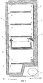
На фиг. 1 схематично изображено поперечное сечение холодильника с емкостью, установленной в стандартные пазы для полок. In FIG. 1 schematically shows a cross-section of a refrigerator with a tank installed in standard grooves for shelves.
На фиг. 2 изображено поперечное сечение холодильника с емкостью, установленной на полку. In FIG. 2 shows a cross section of a refrigerator with a container mounted on a shelf.
На фиг. 3 изображено поперечное сечение холодильника с емкостью, установленной под полкой. In FIG. 3 shows a cross section of a refrigerator with a container mounted under a shelf.
На фиг. 4 - вариант выполнения емкости. In FIG. 4 is an embodiment of a container.
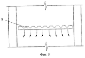
На фиг. 5 - направляющая потока воздуха в виде пластины с отверстиями. In FIG. 5 - air flow guide in the form of a plate with holes.
На фиг. 6 - направляющая потока воздуха в виде 2-х пластин под углом друг к другу;
На фиг. 7 - направляющая потока воздуха в виде 2-х пластин под углом друг к другу и с зазором между ними.In FIG. 6 - air flow guide in the form of 2 plates at an angle to each other;
In FIG. 7 - air flow guide in the form of 2 plates at an angle to each other and with a gap between them.
В соответствии с чертежами (фиг. 1-3) холодильник содержит теплоизолированный корпус 1, теплоизолированную дверь 2, холодильную камеру 3, компрессор 4. Холодильная камера 3 имеет встроенный в заднюю стенку статический испаритель 5 и расположенные по всему объему полки 6 для установки охлаждаемых продуктов, которые могут быть как сплошные, выполненные, например, из стекла, пластмассы, так и решетчатые. В холодильной камере 3 расположена емкость 7, снабженная направляющей 8 потока воздуха. Направляющая 8 потока воздуха расположена по всей ширине емкости 7 и составляет одно целое с емкостью 7 или прикреплена к верхней кромке задней стенки емкости 7. In accordance with the drawings (Figs. 1-3), the refrigerator contains a thermally insulated housing 1, a thermally insulated
Емкость 7 (фиг. 4) состоит из боковых стенок 9, задней стенки 10, днища 11, передней панели 12, которая может быть как жестко прикрепленной к емкости 7, так и откидывающейся, например в виде дверцы 13 (фиг. 3) и направляющих 14. The tank 7 (Fig. 4) consists of
Емкость 7 переставляется с помощью направляющих 14 по объему холодильной камеры 3. При установке емкости 7 непосредственно под полкой 6 холодильной камеры 3 направляющая 8 потока воздуха прикреплена к торцу полки 6, расположенному у задней стенки холодильной камеры 3. Для достижения оптимальных потребительских качеств емкости 7 необходимо придерживаться места ее установки не выше 1/3 длины испарителя от его верха.
На боковых стенках 9 емкости 7 сформированы фиксаторы 15, с помощью которых емкость 7 прилегает к задней стенке холодильной камеры 3, при этом направляющая 8 потока воздуха упирается в заднюю стенку холодильной камеры 3. On the
Направляющая 8 потока воздуха выполнена в виде пластины с отверстиями (фиг. 5) или в виде двух пластин, расположенных под углом друг к другу (фиг. 6) или в виде двух пластин, расположенных под углом друг к другу и с зазором между ними для стекания конденсата (фиг. 7). The
Холодильник работает следующим образом. The refrigerator operates as follows.
В холодильной камере 3 при работе компрессора 4 происходит охлаждение воздуха у задней стенки в районе встроенного испарителя 5. Охлаждаясь, воздух опускается вдоль задней стенки, частично отклоняясь у полок 6 к теплоизолированной двери 2. In the
Основная масса холодного воздуха опускается до емкости 7, а точнее до направляющей 8 потока воздуха, и по ней часть воздуха попадает в рабочий объем емкости 7, тем самым охлаждая продукты, находящиеся в данной емкости. Через зазоры направляющей 8 потока воздуха происходит стекание конденсата. The bulk of the cold air is lowered to the
Остальная часть воздуха спускается по задней стенке холодильной камеры 3, отбирая тепло от продуктов, и отепленный воздух, поднимаясь, возвращается к статическому испарителю 5, где вновь охлаждается, и цикл повторяется до получения необходимой температуры воздуха в холодильной камере 3. The rest of the air descends along the back wall of the
Таким образом, применение емкости позволит обеспечить удобство в пользовании холодильником за счет возможности ее легкой перестановки с одного места на другое в объеме холодильной камеры и при необходимости увеличения объема холодильной камеры - удаление емкости из холодильника. Thus, the use of the container will ensure convenience in using the refrigerator due to the possibility of its easy rearrangement from one place to another in the volume of the refrigerator and, if necessary, increase the volume of the refrigerator, removing the container from the refrigerator.
Claims (4)
Priority Applications (1)
| Application Number | Priority Date | Filing Date | Title |
|---|---|---|---|
| RU2002102587/13A RU2221972C2 (en) | 2002-02-04 | 2002-02-04 | Refrigerator |
Applications Claiming Priority (1)
| Application Number | Priority Date | Filing Date | Title |
|---|---|---|---|
| RU2002102587/13A RU2221972C2 (en) | 2002-02-04 | 2002-02-04 | Refrigerator |
Publications (2)
| Publication Number | Publication Date |
|---|---|
| RU2002102587A RU2002102587A (en) | 2003-10-20 |
| RU2221972C2 true RU2221972C2 (en) | 2004-01-20 |
Family
ID=32090681
Family Applications (1)
| Application Number | Title | Priority Date | Filing Date |
|---|---|---|---|
| RU2002102587/13A RU2221972C2 (en) | 2002-02-04 | 2002-02-04 | Refrigerator |
Country Status (1)
| Country | Link |
|---|---|
| RU (1) | RU2221972C2 (en) |
Cited By (7)
| Publication number | Priority date | Publication date | Assignee | Title |
|---|---|---|---|---|
| WO2006041323A3 (en) * | 2004-10-15 | 2006-06-01 | Foodcap Int Ltd | Methods and apparatus for thermal regulation of perishable products |
| US8317052B2 (en) | 2004-10-15 | 2012-11-27 | Foodcap International Limited | Container, lid and clip therefor |
| RU2478174C2 (en) * | 2007-12-21 | 2013-03-27 | Бсх Бош Унд Сименс Хаусгерете Гмбх | Domestic appliance door and domestic appliance with such door |
| US8899068B2 (en) | 2010-10-28 | 2014-12-02 | Lg Electronics Inc. | Refrigerator comprising vacuum space |
| US9950835B2 (en) | 2004-07-20 | 2018-04-24 | Foodcap International Limited | Product distribution methods and apparatus |
| RU2721856C2 (en) * | 2015-03-20 | 2020-05-25 | Пепсико, Инк. | Cooling system and method |
| RU204841U1 (en) * | 2020-10-02 | 2021-06-15 | Общество с ограниченной ответственностью "ОМЕКС" | Compartment for storing food in a refrigerated display cabinet with a door |
Citations (3)
| Publication number | Priority date | Publication date | Assignee | Title |
|---|---|---|---|---|
| US4217010A (en) * | 1978-12-22 | 1980-08-12 | General Electric Company | Adjustable volume-split refrigerator |
| DE4432439A1 (en) * | 1994-09-12 | 1996-03-14 | Bauknecht Hausgeraete | Refrigerator with two compartments in cooling space |
| RU2076544C1 (en) * | 1994-03-01 | 1997-03-27 | Акционерное общество "Новолипецкий металлургический комбинат" | MULTI-TEMPERATURE REFRIGERATOR |
-
2002
- 2002-02-04 RU RU2002102587/13A patent/RU2221972C2/en not_active IP Right Cessation
Patent Citations (3)
| Publication number | Priority date | Publication date | Assignee | Title |
|---|---|---|---|---|
| US4217010A (en) * | 1978-12-22 | 1980-08-12 | General Electric Company | Adjustable volume-split refrigerator |
| RU2076544C1 (en) * | 1994-03-01 | 1997-03-27 | Акционерное общество "Новолипецкий металлургический комбинат" | MULTI-TEMPERATURE REFRIGERATOR |
| DE4432439A1 (en) * | 1994-09-12 | 1996-03-14 | Bauknecht Hausgeraete | Refrigerator with two compartments in cooling space |
Cited By (13)
| Publication number | Priority date | Publication date | Assignee | Title |
|---|---|---|---|---|
| US9950835B2 (en) | 2004-07-20 | 2018-04-24 | Foodcap International Limited | Product distribution methods and apparatus |
| US8317052B2 (en) | 2004-10-15 | 2012-11-27 | Foodcap International Limited | Container, lid and clip therefor |
| WO2006041323A3 (en) * | 2004-10-15 | 2006-06-01 | Foodcap Int Ltd | Methods and apparatus for thermal regulation of perishable products |
| US9097452B2 (en) | 2004-10-15 | 2015-08-04 | Foodcap International Limited | Methods and apparatus for thermal regulation of perishable products |
| RU2478174C2 (en) * | 2007-12-21 | 2013-03-27 | Бсх Бош Унд Сименс Хаусгерете Гмбх | Domestic appliance door and domestic appliance with such door |
| US8899068B2 (en) | 2010-10-28 | 2014-12-02 | Lg Electronics Inc. | Refrigerator comprising vacuum space |
| US9651292B2 (en) | 2010-10-28 | 2017-05-16 | Lg Electronics Inc. | Refrigerator comprising vacuum space |
| US10337788B2 (en) | 2010-10-28 | 2019-07-02 | Lg Electronics Inc. | Refrigerator comprising vacuum space |
| US11384977B2 (en) | 2010-10-28 | 2022-07-12 | Lg Electronics Inc. | Refrigerator comprising vacuum space |
| US11821678B2 (en) | 2010-10-28 | 2023-11-21 | Lg Electronics Inc. | Refrigerator comprising vacuum space |
| US12196481B2 (en) | 2010-10-28 | 2025-01-14 | Lg Electronics Inc. | Refrigerator comprising vacuum space |
| RU2721856C2 (en) * | 2015-03-20 | 2020-05-25 | Пепсико, Инк. | Cooling system and method |
| RU204841U1 (en) * | 2020-10-02 | 2021-06-15 | Общество с ограниченной ответственностью "ОМЕКС" | Compartment for storing food in a refrigerated display cabinet with a door |
Similar Documents
| Publication | Publication Date | Title |
|---|---|---|
| US6629429B1 (en) | Refrigerator | |
| US7665326B2 (en) | Drawer appliance | |
| RU2565087C2 (en) | Multiple-chamber refrigerating device for storage of fresh food products at different temperatures | |
| US5117649A (en) | Horizontal refrigerator | |
| US6675603B1 (en) | Sealed refrigerator pan assembly | |
| US7096936B1 (en) | Refrigerator with quick chill and thaw system | |
| JP3904866B2 (en) | refrigerator | |
| RU2221972C2 (en) | Refrigerator | |
| US2312326A (en) | Refrigerator | |
| JP5254578B2 (en) | refrigerator | |
| JPH11183014A (en) | refrigerator | |
| EP1124101B1 (en) | Refrigerator appliance with refrigeration grid provided with eutectic plates | |
| JP5165522B2 (en) | refrigerator | |
| US2657544A (en) | Refrigerator tray | |
| JP5617003B2 (en) | refrigerator | |
| EP2921804B1 (en) | Refrigerating apparatus with improved air circulation system | |
| WO2007010267A2 (en) | Improvements in or relating to cold storage | |
| JP2007163066A (en) | refrigerator | |
| CN103673451B (en) | Refrigerating appliance | |
| US2810271A (en) | Refrigerating apparatus | |
| JP2010096473A (en) | Refrigerator | |
| JP2015014452A (en) | refrigerator | |
| JP5620538B2 (en) | refrigerator | |
| JPH01210792A (en) | Refrigerator | |
| JP4746018B2 (en) | refrigerator |
Legal Events
| Date | Code | Title | Description |
|---|---|---|---|
| MM4A | The patent is invalid due to non-payment of fees |
Effective date: 20180205 |