JP5254578B2 - refrigerator - Google Patents

refrigerator Download PDF

Info

Publication number
JP5254578B2
JP5254578B2 JP2007204505A JP2007204505A JP5254578B2 JP 5254578 B2 JP5254578 B2 JP 5254578B2 JP 2007204505 A JP2007204505 A JP 2007204505A JP 2007204505 A JP2007204505 A JP 2007204505A JP 5254578 B2 JP5254578 B2 JP 5254578B2
Authority
JP
Japan
Prior art keywords
cold air
refrigerator
air passage
refrigerator compartment
cold
Prior art date
Legal status (The legal status is an assumption and is not a legal conclusion. Google has not performed a legal analysis and makes no representation as to the accuracy of the status listed.)
Active
Application number
JP2007204505A
Other languages
Japanese (ja)
Other versions
JP2009041793A5 (en
JP2009041793A (en
Inventor
泰治 大城
宏 吉村
Current Assignee (The listed assignees may be inaccurate. Google has not performed a legal analysis and makes no representation or warranty as to the accuracy of the list.)
Sharp Corp
Original Assignee
Sharp Corp
Priority date (The priority date is an assumption and is not a legal conclusion. Google has not performed a legal analysis and makes no representation as to the accuracy of the date listed.)
Filing date
Publication date
Application filed by Sharp Corp filed Critical Sharp Corp
Priority to JP2007204505A priority Critical patent/JP5254578B2/en
Publication of JP2009041793A publication Critical patent/JP2009041793A/en
Publication of JP2009041793A5 publication Critical patent/JP2009041793A5/ja
Application granted granted Critical
Publication of JP5254578B2 publication Critical patent/JP5254578B2/en
Active legal-status Critical Current
Anticipated expiration legal-status Critical

Links

Images

Description

本発明は、貯蔵室に冷熱を放出する部材を備えた冷蔵庫に関する。   The present invention relates to a refrigerator provided with a member for releasing cold heat in a storage room.

従来の冷蔵庫は特許文献1に開示されている。この冷蔵庫は冷蔵室の背面に冷気通路が上下に延びて設けられる。冷気通路の前面には熱伝導性の高い部材が配される。部材には冷気を吐出する吐出口が左右の端部に設けられる。   A conventional refrigerator is disclosed in Patent Document 1. This refrigerator is provided with a cold air passage extending vertically on the back of the refrigerator compartment. A member having high thermal conductivity is disposed on the front surface of the cold air passage. The member is provided with outlets for discharging cool air at the left and right ends.

冷気通路を流通する冷気は吐出口から冷蔵室内に吐出され、冷蔵室内を冷却する。また、冷気通路を流通する冷気の冷熱は部材を介して背面の広い範囲から冷蔵室内に放出される。これにより、冷蔵室内の温度分布を均一にすることができる。   The cold air flowing through the cold air passage is discharged from the discharge port into the refrigerator compartment to cool the refrigerator compartment. Moreover, the cold heat | fever of the cold air which distribute | circulates a cold air | gas channel | path is discharge | released in the refrigerator compartment from the wide range of a back surface via a member. Thereby, the temperature distribution in the refrigerator compartment can be made uniform.

特開2001−66051号公報(第2頁−第6頁、第2図)Japanese Patent Laid-Open No. 2001-66051 (page 2 to page 6, FIG. 2)

しかしながら、上記従来の冷蔵庫によると、冷蔵室が広くなると吐出口から吐出される冷気が冷蔵室の端部まで行き届かない。このため、冷蔵室の温度分布が不均一になる問題があった。冷気を冷蔵室の端部に行き届かせるために冷気通路の横幅を広く形成すると、冷気通路の流路面積が広くなるため冷気の流速が低下する。これにより、下方から冷気通路に流入する冷気が冷気通路の上部に行き届かない。その結果、上記と同様に冷蔵室の温度分布が不均一になる問題がある。   However, according to the conventional refrigerator, the cold air discharged from the discharge port does not reach the end of the refrigerator compartment when the refrigerator compartment is widened. For this reason, there has been a problem that the temperature distribution in the refrigerator compartment becomes non-uniform. If the width of the cold air passage is formed wide in order to allow the cold air to reach the end of the refrigerator compartment, the flow area of the cold air passage is widened, so the flow rate of the cold air is reduced. Thereby, the cold air flowing into the cold air passage from below does not reach the upper portion of the cold air passage. As a result, there is a problem that the temperature distribution in the refrigerator compartment becomes non-uniform similarly to the above.

本発明は、容積の広い貯蔵室の温度分布を均一にできる冷蔵庫を提供することを目的とする。   An object of this invention is to provide the refrigerator which can make uniform temperature distribution of the storage chamber with a large volume.

上記目的を達成するために本発明は、貯蔵物を収納する貯蔵室と、前記貯蔵室に流入する冷気を生成する冷却器と、前記貯蔵室の背面に配されて前記冷却器からの冷気が流通する冷気通路と、前記冷気通路の周囲に延びて前記冷気通路の前面側を覆うとともに前記冷気通路を流通する冷気の冷熱を伝えて前記貯蔵室内に放出する部材と、冷気が流入する側の前記冷気通路に配される断熱部材と、前記冷気通路を流通する冷気を前記貯蔵室に吐出する吐出口とを備えたことを特徴としている。   In order to achieve the above object, the present invention provides a storage chamber for storing stored items, a cooler for generating cold air flowing into the storage chamber, and a cooler disposed on the back surface of the storage chamber for receiving the cool air from the cooler. A cold air passage that circulates, a member that extends around the cold air passage to cover the front side of the cold air passage, transmits cold heat of the cold air that flows through the cold air passage, and discharges it into the storage chamber; A heat insulating member disposed in the cold air passage and a discharge port for discharging the cold air flowing through the cold air passage to the storage chamber are provided.

この構成によると、冷却器で生成された冷気は冷気通路を流通して吐出口から吐出され、貯蔵室内を流通して貯蔵物が冷却される。冷気通路を流通する冷気の冷熱は部材を熱伝導して貯蔵室の背面の広い範囲から貯蔵室内に放出される。この時、貯蔵室背面の冷気通路に流入した直後の冷気の冷熱は断熱部材によって断熱される。   According to this configuration, the cold air generated by the cooler flows through the cold air passage and is discharged from the discharge port, and flows through the storage chamber to cool the stored item. The cold heat of the cold air flowing through the cold air passage is conducted through the member and discharged into the storage chamber from a wide area on the back surface of the storage chamber. At this time, the cold heat of the cool air immediately after flowing into the cool air passage on the back of the storage chamber is insulated by the heat insulating member.

また本発明は上記構成の冷蔵庫において、前記部材を着脱自在にしたことを特徴としている。   Further, the present invention is characterized in that in the refrigerator configured as described above, the member is detachable.

また本発明は上記構成の冷蔵庫において、前記吐出口を前記冷気通路の側端部に配置したことを特徴としている。この構成によると、吐出口と貯蔵室の側壁とが接近して配置される。   Moreover, the present invention is characterized in that, in the refrigerator having the above-described configuration, the discharge port is disposed at a side end portion of the cold air passage. According to this configuration, the discharge port and the side wall of the storage chamber are arranged close to each other.

また本発明は上記構成の冷蔵庫において、前記冷気通路を形成する樹脂成形品から成るダクトの前面に前記部材を配置して前記吐出口を前記ダクトの側壁に開口し、前記部材によって前記側壁の外側を覆ったことを特徴としている。この構成によると、ダクトの側壁に開口する吐出口から貯蔵室内に吐出された冷気は部材の端部の背面側で拡散して貯蔵室内を流通する。   According to the present invention, in the refrigerator configured as described above, the member is disposed on a front surface of a duct made of a resin molded product forming the cold air passage, and the discharge port is opened on a side wall of the duct. It is characterized by covering. According to this configuration, the cold air discharged into the storage chamber from the discharge port opened in the side wall of the duct diffuses on the back side of the end portion of the member and circulates in the storage chamber.

また本発明は上記構成の冷蔵庫において、前記部材の少なくとも一部に前記冷気通路を流通する冷気が直接接することを特徴としている。   Moreover, the present invention is characterized in that in the refrigerator configured as described above, cold air flowing through the cold air passage is in direct contact with at least a part of the member.

また本発明は上記構成の冷蔵庫において、前記冷気通路は下部で左右に分岐して上下方向に延びるとともに上部の連結部で連結される第1、第2分岐路を有し、前記冷却器で生成された冷気を下方から前記冷気通路に流入させたことを特徴としている。この構成によると、貯蔵室の下方から冷気通路に流入する冷気は第1、第2分岐路に分岐して上昇して貯蔵室に吐出される。また、一部の冷気は第1、第2分岐路の一方から上部の連結部を通って他方を流通する。   Further, the present invention provides the refrigerator having the above-described configuration, wherein the cold air passage has a first and a second branch passage that branches from side to side in the lower part and extends in the vertical direction and is connected by a connection part in the upper part, and is generated by the cooler. It is characterized in that the cooled cold air flows into the cold air passage from below. According to this configuration, the cold air flowing into the cold air passage from below the storage chamber is branched into the first and second branch passages, rises, and is discharged into the storage chamber. Some of the cool air flows from one of the first and second branch paths to the other through the upper connecting portion.

また本発明は上記構成の冷蔵庫において、前記吐出口を前記連結部に設けたことを特徴としている。この構成によると、貯蔵室の略中央上部から冷気が吐出される。   Moreover, the present invention is characterized in that, in the refrigerator having the above-described configuration, the discharge port is provided in the connecting portion. According to this structure, cold air is discharged from the substantially upper center of the storage chamber.

また本発明は上記構成の冷蔵庫において、前記貯蔵室の下方に断熱壁を介して他の貯蔵室を配置し、前記冷気通路に冷気を送出する送風機と前記断熱壁とを正面投影において重なる位置に配置したことを特徴としている。この構成によると、貯蔵室の下方に配された冷却器で生成された冷気が送風機の駆動によって冷気通路に流入する。   Further, in the refrigerator having the above-described configuration, another storage room is disposed below the storage room via a heat insulating wall, and the blower for sending the cold air to the cold air passage and the heat insulating wall overlap with each other in a front projection. It is characterized by the arrangement. According to this structure, the cold air | gas produced | generated with the cooler distribute | arranged below the storage room flows in into a cold air | gas channel | path by the drive of an air blower.

また本発明は上記構成の冷蔵庫において、前記部材の表面に結露水を溜める凹部または凸部を設けたことを特徴としている。この構成によると、部材の表面に発生する結露水は流下して凹部の内面または凸部の上面で保持される。凹部または凸部で保持される結露水はその後蒸発して貯蔵室内が保湿される。   Moreover, the present invention is characterized in that in the refrigerator configured as described above, a concave portion or a convex portion for collecting condensed water is provided on the surface of the member. According to this configuration, the condensed water generated on the surface of the member flows down and is held on the inner surface of the concave portion or the upper surface of the convex portion. The condensed water held in the recesses or protrusions is then evaporated and the storage chamber is moisturized.

また本発明は上記構成の冷蔵庫において、前記凹部または前記凸部の周面に前記吐出口を形成したことを特徴としている。この構成によると、凹部の内周面または凸部の外周面に開口した吐出口から吐出された冷気は部材に沿って流通する。   Moreover, the present invention is characterized in that, in the refrigerator having the above-described configuration, the discharge port is formed on a peripheral surface of the concave portion or the convex portion. According to this structure, the cold air discharged from the discharge port opened on the inner peripheral surface of the concave portion or the outer peripheral surface of the convex portion flows along the member.

本発明によると、貯蔵室背面の冷気通路を流通する冷気の冷熱を放出する部材を冷気通路の周囲に延びて設けたので、冷気通路の流路面積を必要な大きさに保って形成するとともに部材によってより広い範囲から冷熱を貯蔵室に放出することができる。これにより、冷気の流速の著しい低下を抑制して冷気通路内を冷気が行き届き、冷熱が貯蔵室全体に行き届く。従って、容積の広い貯蔵室の温度分布を均一にできる。   According to the present invention, the member that discharges the cold heat of the cold air flowing through the cold air passage at the back of the storage chamber is provided to extend around the cold air passage, so that the flow passage area of the cold air passage is maintained at a required size and formed. The member can release cold heat from a wider range to the storage chamber. Thereby, the remarkable fall of the flow rate of cold air is suppressed, cold air reaches the inside of the cold air passage, and cold heat reaches the entire storage room. Therefore, the temperature distribution in the storage chamber having a large volume can be made uniform.

また、部材が貯蔵室の開口部から離れた背面に配されるため開口部から外気が流入しても部材に到達するまでに降温され、部材に発生する結露を低減することができる。更に、冷気通路に流入した直後の低温の冷気は断熱部材によって冷熱が断熱されるため貯蔵室の背面に発生する結露を低減することができる。   In addition, since the member is arranged on the back surface away from the opening of the storage chamber, even if outside air flows in from the opening, the temperature is lowered until the member reaches the member, and condensation generated on the member can be reduced. Furthermore, since the cold heat immediately after flowing into the cold air passage is thermally insulated by the heat insulating member, dew condensation generated on the back surface of the storage chamber can be reduced.

また本発明によると、部材を着脱自在にしたので、部材を容易に清掃して貯蔵室内を清潔に維持することができる。   Further, according to the present invention, since the member is made detachable, the member can be easily cleaned to keep the storage chamber clean.

また本発明によると、吐出口を冷気通路の側端部に配置したので、貯蔵室の側端部を更に冷却して貯蔵室の温度分布をより均一にすることができる。   According to the present invention, since the discharge port is arranged at the side end of the cold air passage, the side end of the storage chamber can be further cooled to make the temperature distribution in the storage chamber more uniform.

また本発明によると、冷気通路を形成するダクトの側壁に開口して吐出口を形成し、部材によってダクトの側壁の外側を覆ったので、貯蔵室に吐出された冷気が部材に沿って拡散して流通する。従って、部材に伝えられる冷熱量が増加して貯蔵室の温度分布をより均一にできる。   Further, according to the present invention, since the discharge port is formed by opening on the side wall of the duct forming the cool air passage, and the outside of the side wall of the duct is covered by the member, the cool air discharged into the storage chamber diffuses along the member. Circulate. Therefore, the amount of cold heat transmitted to the member increases, and the temperature distribution in the storage chamber can be made more uniform.

また本発明によると、部材の少なくとも一部に冷気通路を流通する冷気が直接接するので、部材に伝えられる冷熱量をより増加させることができる。   According to the present invention, since the cold air flowing through the cold air passage is in direct contact with at least a part of the member, the amount of cold heat transmitted to the member can be further increased.

また本発明によると、冷気通路が下部で第1、第2分岐路に分岐するため、冷気通路の流路面積を増加させることなく貯蔵室の端部に冷気を吐出させることができる。また、第1、第2分岐路の上部が連結部で連結されるため、第1、第2分岐路に分岐した冷気量に差が生じても連結部を介して均一化される。従って、貯蔵室に吐出される冷気量を左右で略同じにして温度分布を均一にすることができる。   According to the present invention, since the cold air passage is branched into the first and second branch passages at the lower portion, the cold air can be discharged to the end of the storage chamber without increasing the flow passage area of the cold air passage. Moreover, since the upper part of the 1st, 2nd branch path is connected by a connection part, even if a difference arises in the quantity of cold air branched to the 1st, 2nd branch path, it equalizes via a connection part. Accordingly, it is possible to make the temperature distribution uniform by making the amount of cool air discharged into the storage chamber substantially the same on the left and right.

また本発明によると、吐出口を連結部に設けたので、貯蔵室の略中央上部から冷気が吐出される。従って、貯蔵室の端部及び中央部に冷気が吐出され、貯蔵室の温度分布をより均一にすることができる。   According to the present invention, since the discharge port is provided in the connecting portion, the cold air is discharged from the substantially upper center of the storage chamber. Therefore, cold air is discharged to the end and center of the storage chamber, and the temperature distribution in the storage chamber can be made more uniform.

また本発明によると、貯蔵室の下方に断熱壁と送風機とを正面投影において重なる位置に配置したので、貯蔵室と送風機とが接近して配置される。このため、貯蔵室の容積が大きくても送風機に近い吐出口と遠い吐出口との間で吐出される冷気流の強さの差が小さくなる。従って、貯蔵室の温度分布を更に均一にすることができる。また、貯蔵室内に送風機が配置されないため、貯蔵室内の容積を広く確保して冷蔵庫の容積効率を向上することができる。   Moreover, according to this invention, since the heat insulation wall and the air blower were arrange | positioned in the position which overlaps in a front projection below the storage chamber, a storage chamber and an air blower are arrange | positioned closely. For this reason, even if the volume of a store room is large, the difference in the intensity | strength of the cold airflow discharged between the discharge outlet close | similar to a fan and a distant discharge opening becomes small. Therefore, the temperature distribution in the storage chamber can be made more uniform. Moreover, since the blower is not arranged in the storage chamber, it is possible to secure a large volume in the storage chamber and improve the volumetric efficiency of the refrigerator.

また本発明によると、冷気通路の周囲に延びる部材の表面に結露水を溜める凹部または凸部を設けたので、広い範囲で結露水を保持することができる。従って、結露水の蒸発による貯蔵室内の保湿効果を向上することができる。   Further, according to the present invention, since the concave portion or the convex portion for accumulating the dew condensation water is provided on the surface of the member extending around the cold air passage, the dew condensation water can be held in a wide range. Therefore, the moisturizing effect in the storage chamber due to evaporation of condensed water can be improved.

また本発明によると、凹部または凸部の周面に吐出口を形成したので、吐出口から吐出された冷気が部材に沿って流通する。従って、部材に伝えられる冷熱量が増加して貯蔵室の温度分布をより均一にできる。   According to the present invention, since the discharge port is formed on the peripheral surface of the concave portion or the convex portion, the cold air discharged from the discharge port flows along the member. Therefore, the amount of cold heat transmitted to the member increases, and the temperature distribution in the storage chamber can be made more uniform.

以下に本発明の実施形態を図面を参照して説明する。図1、図2は第1実施形態の冷蔵庫を示す正面図及び右側面図である。冷蔵庫1は上部に扉2aで開閉される冷蔵室2(貯蔵室)が配される。冷蔵室2の下方には扉3a、4aで開閉される温度切替室3及び製氷室4が左右に並設される。温度切替室3及び製氷室4の下方には扉6aで開閉される冷凍室6が配され、冷凍室6の下方に扉5aで開閉される野菜室5が配されている。   Embodiments of the present invention will be described below with reference to the drawings. 1 and 2 are a front view and a right side view showing the refrigerator of the first embodiment. The refrigerator 1 is provided with a refrigerator compartment 2 (storage compartment) that is opened and closed by a door 2a. Below the refrigerator compartment 2, a temperature switching chamber 3 and an ice making chamber 4 that are opened and closed by doors 3a and 4a are arranged side by side. Below the temperature switching chamber 3 and the ice making chamber 4, a freezing room 6 that is opened and closed by a door 6 a is arranged, and below the freezing room 6 is a vegetable room 5 that is opened and closed by a door 5 a.

冷蔵室2は貯蔵物を冷蔵保存し、野菜室5は冷蔵室2よりも高い室内温度(約8℃)で野菜を冷却保存する。温度切替室3は詳細を後述するように、使用者により室温を切り替えられるようになっている。冷凍室6は貯蔵物を冷凍保存し、製氷室4は冷凍室6に連通して氷を製氷する。尚、製氷室4及び冷凍室6は氷点以下に維持され、本明細書において製氷室4は冷凍室6の一部を構成する。   The refrigerator compartment 2 stores stored items in a refrigerator, and the vegetable compartment 5 cools and preserves vegetables at a room temperature (about 8 ° C.) higher than the refrigerator compartment 2. As will be described later in detail, the temperature switching chamber 3 can be switched by the user at room temperature. The freezer 6 stores the stored items in a frozen state, and the ice making chamber 4 communicates with the freezer 6 to make ice. The ice making room 4 and the freezing room 6 are maintained below the freezing point, and the ice making room 4 constitutes a part of the freezing room 6 in this specification.

図3、図4は冷蔵庫1の右側面断面図及び正面図である。冷蔵庫1の本体部は外箱1aと内箱1bとの間に発泡断熱材1cが充填されている。製氷室4及び温度切替室3と冷蔵室2との間は断熱壁7により隔離され、冷凍室6と野菜室5との間は断熱壁8により隔離される。また、温度切替室3と冷凍室6との間は断熱壁35により隔離され、温度切替室3と製氷室4との間は縦断熱壁36により隔離されている。   3 and 4 are a right side cross-sectional view and a front view of the refrigerator 1. The main body of the refrigerator 1 is filled with a foam heat insulating material 1c between the outer box 1a and the inner box 1b. The ice making chamber 4 and the temperature switching chamber 3 are separated from the refrigerator compartment 2 by a heat insulating wall 7, and the freezer compartment 6 and the vegetable compartment 5 are separated from each other by a heat insulating wall 8. Further, the temperature switching chamber 3 and the freezing chamber 6 are isolated by a heat insulating wall 35, and the temperature switching chamber 3 and the ice making chamber 4 are isolated by a vertical heat insulating wall 36.

発泡断熱材1cはウレタン発泡断熱材等から成り、外箱1aと内箱1bとの間に充填される際に断熱壁7、8内に同時に充填される。即ち、発泡断熱材1cの原液が外箱1aと内箱1bとの間とこれに連通する断熱壁7、8に同時に注入され、一体に発泡される。これにより、断熱壁7、8を簡単に薄く形成することができる。従って、冷蔵室2の容積を広く確保することができる。   The foam heat insulating material 1c is made of urethane foam heat insulating material or the like, and is filled in the heat insulating walls 7 and 8 simultaneously when filled between the outer box 1a and the inner box 1b. That is, the stock solution of the foam heat insulating material 1c is injected simultaneously between the outer box 1a and the inner box 1b and into the heat insulating walls 7 and 8 communicating with the outer box 1a, and is foamed integrally. Thereby, the heat insulation walls 7 and 8 can be easily formed thinly. Therefore, the volume of the refrigerator compartment 2 can be ensured widely.

また、断熱壁7、8の外装は内箱1bと別部材から成り、発泡断熱材1cの充填前は断熱壁7、8の側面が開口して内箱1bが断熱壁7、8の側面に対向して開口する。発泡断熱材1cの充填により断熱壁7、8の側面の開口と内箱1bの開口とが連結して一体となる。   The exterior of the heat insulating walls 7 and 8 is made of a separate member from the inner box 1b. Before filling the foam heat insulating material 1c, the side surfaces of the heat insulating walls 7 and 8 are opened and the inner box 1b is formed on the side surfaces of the heat insulating walls 7 and 8. Open oppositely. By filling the foam heat insulating material 1c, the openings on the side surfaces of the heat insulating walls 7 and 8 and the opening of the inner box 1b are connected and integrated.

これにより、断熱壁7、8によって隔離された温度帯の異なる各貯蔵室間での冷気や暖気の漏れが防止される。従って、熱ロスの低減による省エネルギー化を図ることができる。また、断熱壁7、8の振動や、該振動による断熱壁7、8と内箱1bとの摺動によって発生する異常音を防止することができる。加えて、一体形成による構造的な強度を向上することができる。   Thereby, the leakage of cold air or warm air between the storage chambers separated by the heat insulating walls 7 and 8 in different temperature zones is prevented. Therefore, it is possible to save energy by reducing heat loss. Moreover, the abnormal noise which generate | occur | produces by the vibration of the heat insulation walls 7 and 8 and the sliding of the heat insulation walls 7 and 8 and the inner case 1b by this vibration can be prevented. In addition, the structural strength by the integral formation can be improved.

製氷室4、冷凍室6、野菜室5及び温度切替室3には貯蔵物を収納する収納ケース43が設けられる。冷蔵室2には貯蔵物を載置する複数の収納棚41が設けられる。冷蔵室2の扉2aには複数の収納ポケット42が設けられる。これらにより、冷蔵庫1の使い勝手が向上されている。   The ice making room 4, the freezing room 6, the vegetable room 5 and the temperature switching room 3 are provided with a storage case 43 for storing stored items. The refrigerator compartment 2 is provided with a plurality of storage shelves 41 on which stored items are placed. A plurality of storage pockets 42 are provided on the door 2 a of the refrigerator compartment 2. Thereby, the usability of the refrigerator 1 is improved.

また、冷蔵室2内の下部には上面が仕切板41aにより仕切られて隔離された隔離室から成るチルド室21が設けられる。チルド室21は冷蔵室2と異なる温度帯の例えばチルド温度帯(約0℃)に維持される。チルド室21には貯蔵物を収納する収納ケース107が配される。チルド室21に替えて氷温(約−3℃)に維持される氷温室にしてもよい。   In addition, a chilled chamber 21 including an isolation chamber whose upper surface is partitioned and separated by a partition plate 41a is provided at a lower portion in the refrigerator compartment 2. The chilled chamber 21 is maintained in a temperature range different from that of the refrigerator compartment 2, for example, a chilled temperature range (about 0 ° C.). The chilled chamber 21 is provided with a storage case 107 for storing stored items. Instead of the chilled chamber 21, an ice greenhouse maintained at an ice temperature (about −3 ° C.) may be used.

野菜室5の背後には機械室50が設けられ、機械室50内に圧縮機57が配される。圧縮機57には凝縮器、膨張器(いずれも不図示)及び冷却器11が接続され、圧縮機57の駆動によりイソブタン等の冷媒が循環して冷凍サイクルが運転される。これにより、冷却器11が冷凍サイクルの低温側となる。   A machine room 50 is provided behind the vegetable room 5, and a compressor 57 is disposed in the machine room 50. The compressor 57 is connected to a condenser, an expander (not shown), and a cooler 11, and a refrigerant such as isobutane is circulated by driving the compressor 57 to operate a refrigeration cycle. Thereby, the cooler 11 becomes the low temperature side of the refrigeration cycle.

機械室50の後部には電装部51が設けられる。電装部51は冷蔵庫1の本体部に取付けられる背面側が開口した電装ボックス52を有し、機械室50の背面を塞ぐ背面カバー50aにより密閉される。電装ボックス52は金属板の絞り加工により形成され、放熱面積が大きく電装部品の発熱を容易に放熱できるとともに電装部51内を容易に密閉することができる。   An electrical component 51 is provided at the rear of the machine room 50. The electrical component 51 has an electrical component box 52 that is attached to the main body of the refrigerator 1 and has an open rear side. The electrical component 51 is sealed by a rear cover 50 a that closes the rear surface of the machine room 50. The electrical box 52 is formed by drawing a metal plate, has a large heat radiation area, can easily dissipate heat generated by the electrical components, and can easily seal the interior of the electrical component 51.

電装部51には圧縮機57や各送風機等を制御する制御回路を有した制御基板53を含む電装部品が内装される。電装部51を機械室50内に設置したので、冷蔵室2の背後に設置した場合に比して使用頻度の高い冷蔵室2の容積を広く確保し、冷蔵庫1の容積効率を向上して利便性を向上することができる。   The electrical component 51 includes electrical components including a control board 53 having a control circuit for controlling the compressor 57 and each blower. Since the electrical unit 51 is installed in the machine room 50, the volume of the refrigerator room 2, which is frequently used, is increased as compared with the case where it is installed behind the refrigerator room 2, and the volume efficiency of the refrigerator 1 is improved. Can be improved.

冷凍室6の背後には背面板6bで仕切られる冷気通路31が設けられる。冷蔵室2の背後には冷蔵室ダンパ20を介して冷気通路31と連通する冷気通路32が設けられる。冷気通路31は仕切板31cにより前部31aと後部31bとに仕切られ、後部31bに冷却器11が配される。冷却器11が冷凍室6の背面側に配されるため、冷却器11の冷熱が仕切板31c、前部31a、背面板6bを介して冷凍室6側へ放出される。このため、冷凍室6が効率よく間接冷却され、冷却効率が向上されるようになっている。   Behind the freezer compartment 6 is provided a cold air passage 31 partitioned by a back plate 6b. Behind the refrigerator compartment 2 is provided a cold air passage 32 communicating with the cold air passage 31 via the refrigerator compartment damper 20. The cool air passage 31 is partitioned into a front part 31a and a rear part 31b by a partition plate 31c, and the cooler 11 is arranged in the rear part 31b. Since the cooler 11 is arranged on the back side of the freezer compartment 6, the cold heat of the cooler 11 is released to the freezer compartment 6 side through the partition plate 31c, the front part 31a, and the back plate 6b. For this reason, the freezer compartment 6 is indirectly cooled efficiently, and the cooling efficiency is improved.

冷凍サイクルの低温側となる冷却器11と冷気通路31を流通する空気とが熱交換して冷気が生成される。冷却器11の下方には冷却器11を除霜する除霜ヒータ33が設けられている。除霜ヒータ33の下方には除霜による水を受けるつゆ受皿63が設けられる。つゆ受皿63にはドレンパイプ64が設けられ、機械室50内に配された蒸発皿(不図示)にドレンパイプ64を介してドレン水が導かれる。   The cooler 11 on the low temperature side of the refrigeration cycle exchanges heat with the air flowing through the cold air passage 31 to generate cold air. A defrost heater 33 for defrosting the cooler 11 is provided below the cooler 11. Below the defrost heater 33, a soup saucer 63 for receiving water by defrost is provided. The soy saucer 63 is provided with a drain pipe 64, and drain water is guided to an evaporating dish (not shown) disposed in the machine room 50 via the drain pipe 64.

冷気通路31、32内には冷凍室送風機12及び冷蔵室送風機23がそれぞれ配される。詳細を後述するように、冷却器11で生成された冷気は冷凍室送風機12の駆動により冷気通路31の前部31aを流通し、冷凍室6、製氷室4及び温度切替室3に供給される。また、該冷気は冷蔵室送風機23の駆動により、冷気通路32を介して冷蔵室2、チルド室21及び野菜室5に供給される。   In the cold air passages 31 and 32, the freezer compartment fan 12 and the refrigerator compartment fan 23 are respectively arranged. As will be described in detail later, the cold air generated by the cooler 11 flows through the front portion 31 a of the cold air passage 31 by driving the freezer compartment fan 12, and is supplied to the freezer compartment 6, the ice making chamber 4, and the temperature switching chamber 3. . The cold air is supplied to the refrigerator compartment 2, the chilled compartment 21 and the vegetable compartment 5 through the cold passage 32 by driving the refrigerator compartment fan 23.

冷凍室送風機12は軸流ファンから成り、排気側を前方上方に向けて配置される。これにより、下方の冷却器11で冷却された冷気を冷凍室送風機12の斜め後方から効率よく吸い込むことができる。また、冷気通路31の前部31aに向かって前方上方に冷気を送出し、製氷室4に吐出するとともに上方の冷気通路32に導く。従って、上方へ効率よく冷気を流通させて低騒音化及び省エネルギー化を図ることができる。   The freezer compartment fan 12 is composed of an axial fan, and is disposed with the exhaust side facing forward and upward. Thereby, the cold air cooled by the lower cooler 11 can be efficiently sucked from the diagonally rear side of the freezer compartment fan 12. Further, the cool air is sent forward and upward toward the front portion 31 a of the cool air passage 31, discharged to the ice making chamber 4, and led to the upper cool air passage 32. Accordingly, it is possible to efficiently distribute the cool air upward to reduce noise and save energy.

冷蔵室送風機23は軸流ファンから成り、軸方向を上下方向に向けて配置される。これにより、上記と同様に、上方へ効率よく冷気を流通させて低騒音化及び省エネルギー化を図ることができる。また、冷蔵室送風機23が高さ方向に低くなり、冷蔵室送風機23と断熱壁7とを正面投影において重なるように同一水平面内に配置することができる。   The refrigerating room blower 23 is composed of an axial fan, and is arranged with the axial direction directed up and down. Thereby, similarly to the above, it is possible to efficiently distribute the cool air upward to reduce noise and save energy. Moreover, the refrigerator compartment fan 23 becomes low in a height direction, and the refrigerator compartment fan 23 and the heat insulation wall 7 can be arrange | positioned in the same horizontal surface so that it may overlap in a front projection.

これにより、使用頻度の高い冷蔵室2の背後に冷蔵室送風機23が配置されず、冷気通路32の奥行を狭くすることができる。即ち、冷気通路32の奥行きは冷蔵室送風機23の吐出側で例えば80mmに形成され、空気流の下流側に向かって徐々に狭くなって例えば12mmに形成されている。この時、冷気通路32の左右方向の幅の合計は冷蔵室送風機23の吐出側付近よりも広く形成される。これにより、冷気通路32の通風面積を確保して冷気流量が維持され、送風効率の低下が防止されている。従って、狭くなった冷気通路32の前方の冷蔵室2の奥行きが増加し、冷蔵室2の容積を広く確保することができる。   Thereby, the refrigerator air blower 23 is not arrange | positioned behind the refrigerator compartment 2 with a high usage frequency, and the depth of the cold air | gas channel | path 32 can be narrowed. That is, the depth of the cold air passage 32 is formed to 80 mm, for example, on the discharge side of the refrigerator fan 23, and is gradually narrowed toward the downstream side of the air flow, for example, 12 mm. At this time, the total width in the left-right direction of the cold air passage 32 is formed wider than the vicinity of the discharge side of the refrigerator compartment fan 23. Thereby, the ventilation area of the cool air passage 32 is ensured, the cool air flow rate is maintained, and the reduction of the blowing efficiency is prevented. Therefore, the depth of the refrigerator compartment 2 in front of the narrowed cold air passage 32 is increased, and the volume of the refrigerator compartment 2 can be secured widely.

尚、断熱壁7を同図に示すよりも上方に設けて冷蔵室2の容積を維持し、温度切替室3や製氷室4の容積を広く確保してもよい。また、冷蔵室送風機23を遠心ファンにより形成してもよい。この時、遠心ファンは吸込み側を下方に向け、吐出側を左右方向に向けて配置され、空気の吐出時または吐出後に空気流を上方に向けるようにするとよい。   In addition, the heat insulation wall 7 may be provided above the figure to maintain the volume of the refrigerator compartment 2, and the volume of the temperature switching chamber 3 and the ice making chamber 4 may be secured widely. Moreover, you may form the refrigerator compartment fan 23 with a centrifugal fan. At this time, the centrifugal fan may be arranged with the suction side facing downward and the discharge side facing left and right, so that the air flow is directed upward during or after air discharge.

また、冷蔵室送風機23が断熱壁7と上下方向で重なる領域に設けられるため、冷凍室送風機12は製氷室4の上部に配される製氷皿62から離れた低い位置に配置される。しかし、冷凍室送風機12の冷気の吐出し方向が前方上方の製氷皿62の方向になっているため、製氷皿62の貯水を効率よく冷却することができる。   In addition, since the refrigerating room blower 23 is provided in a region that overlaps the heat insulating wall 7 in the vertical direction, the freezing room blower 12 is disposed at a low position away from the ice making tray 62 disposed above the ice making room 4. However, since the discharge direction of the cold air from the freezer blower 12 is the direction of the ice tray 62 at the upper front, the water stored in the ice tray 62 can be efficiently cooled.

冷気通路32の前面側はパネル組品120により覆われる。パネル組品120は発泡樹脂成形品等から成るダクト102の前面に樹脂成形品から成るパネル100が配され、その前面側に高熱伝導性を有する部材101が配される。ダクト102には断熱性の高い発泡ポリスチレン等の発泡樹脂が用いられる。パネル100には加工が容易なPP、PS、ABS等の樹脂が用いられる。部材101にはアルミニウムや耐食性の高いステンレス等の金属が用いられる。   The front side of the cold air passage 32 is covered with the panel assembly 120. In the panel assembly 120, a panel 100 made of a resin molded product is arranged on the front surface of a duct 102 made of a foamed resin molded product, and a member 101 having high thermal conductivity is arranged on the front side thereof. For the duct 102, a foamed resin such as foamed polystyrene having high heat insulation is used. The panel 100 is made of a resin such as PP, PS, or ABS that can be easily processed. The member 101 is made of metal such as aluminum or stainless steel having high corrosion resistance.

ダクト102はチルド室21に面した下部の略全面を所定の厚みで覆って断熱する断熱部102dを有している。これにより、冷気通路32は冷却器11から冷気が流入する側に断熱部材が配される。冷却器11から冷気通路32に流入した直後の低温の冷気は断熱部102dによって冷熱が断熱される。このため、冷蔵室2内に配されたチルド室21の背面に発生する結露を低減することができる。   The duct 102 has a heat insulating portion 102d that covers and heat-insulates a substantially entire lower portion facing the chilled chamber 21 with a predetermined thickness. As a result, the cool air passage 32 is provided with a heat insulating member on the side where the cool air flows from the cooler 11. The low temperature cold air immediately after flowing into the cold air passage 32 from the cooler 11 is thermally insulated by the heat insulating portion 102d. For this reason, the dew condensation which generate | occur | produces on the back surface of the chilled room 21 distribute | arranged in the refrigerator compartment 2 can be reduced.

冷蔵室2の天井面にはランプカバー109により覆われた照明ランプ110が配される。照明ランプ110の出射光は上方から冷蔵室2内を照明するとともに、部材101の表面で反射して後方から冷蔵室2内を照明する。これにより、冷蔵室2内をより明るくすることができる。ランプカバー109や収納棚41を半透明または透明なガラスや樹脂(ABS、PS、ポリカーボネイト、アクリル等)により形成するとより望ましい。   An illumination lamp 110 covered with a lamp cover 109 is disposed on the ceiling surface of the refrigerator compartment 2. The light emitted from the illumination lamp 110 illuminates the inside of the refrigerator compartment 2 from above, and reflects off the surface of the member 101 to illuminate the inside of the refrigerator compartment 2 from behind. Thereby, the inside of the refrigerator compartment 2 can be made brighter. It is more desirable that the lamp cover 109 and the storage shelf 41 are made of translucent or transparent glass or resin (ABS, PS, polycarbonate, acrylic, etc.).

図4は冷蔵庫1の正面断面図を示している。部材101はパネル100に突設される係合爪100aと取付部材101aによってパネル100の上部に着脱自在に設けられる。従って、部材101を容易に清掃して冷蔵室2内を清潔に維持することができる。   FIG. 4 shows a front sectional view of the refrigerator 1. The member 101 is detachably provided on the upper portion of the panel 100 by an engaging claw 100a projecting from the panel 100 and an attachment member 101a. Therefore, the member 101 can be easily cleaned and the inside of the refrigerator compartment 2 can be kept clean.

ダクト102はパネル100に突設された係合爪(不図示)によってパネル100に取り付けられる。これにより、ダクト102、パネル100及び部材101が一体化される。パネル組品120はパネル100の背面側周部に設けられた係合爪(不図示)により内箱1bに取り付けられている。取付部材101aにはビスや樹脂製の先端が矢じり状の押しピン等が用いられる。   The duct 102 is attached to the panel 100 by an engaging claw (not shown) protruding from the panel 100. Thereby, the duct 102, the panel 100, and the member 101 are integrated. The panel assembly 120 is attached to the inner box 1b by an engaging claw (not shown) provided on the back side peripheral portion of the panel 100. As the attachment member 101a, a screw or a resin-made push pin with a pointed arrow shape is used.

尚、部材101の下端を境界にしてパネル100、ダクト102を上下に分割し、部材101、パネル100の上部及びダクト102の上部を組品にして上記と同様に着脱自在に形成してもよい。   The panel 100 and the duct 102 may be divided into upper and lower parts with the lower end of the member 101 as a boundary, and the member 101, the upper part of the panel 100, and the upper part of the duct 102 may be assembled to be detachable as described above. .

冷気通路32はダクト102によって下部で分岐した第1、第2分岐路32a、32bが形成される。第1、第2分岐路32a、32bは冷蔵室2の上部で連結部32cにより連結される。冷気通路32の下部にはチルド室21に冷気吐出する吐出口103a、103bがパネル100に開口して設けられる。   The cold air passage 32 is formed with first and second branch passages 32 a and 32 b branched at the lower portion by the duct 102. The first and second branch paths 32a and 32b are connected to each other at the upper portion of the refrigerator compartment 2 by a connecting portion 32c. Discharge ports 103 a and 103 b for discharging cool air to the chilled chamber 21 are provided in the lower portion of the cool air passage 32 so as to open to the panel 100.

第1、第2分岐路32a、32bの上端には冷蔵室2に冷気を吐出する吐出口105a、105bがそれぞれ部材101に開口して設けられる。連結部32cには冷蔵室2の略中央上部に冷気を吐出する吐出口105cが部材101に開口して設けられる。   Discharge ports 105a and 105b for discharging cold air to the refrigerator compartment 2 are provided at the upper ends of the first and second branch paths 32a and 32b, respectively, so as to open to the member 101. The connecting portion 32 c is provided with a discharge port 105 c that discharges cool air in the upper part of the center of the refrigerator compartment 2 so as to open to the member 101.

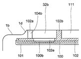
図5は図4のA−A断面図を示し、第2分岐路32bの断面を示している。第1分岐路32aと第2分岐路32bとは対称に形成される。ダクト102は後方に突出する突起部102a、102bを有し、突起部102a、102bが内箱1bに当接して第2分岐路32bが形成される。   FIG. 5 is a cross-sectional view taken along the line AA of FIG. 4 and shows a cross section of the second branch path 32b. The first branch path 32a and the second branch path 32b are formed symmetrically. The duct 102 has protrusions 102a and 102b protruding rearward, and the protrusions 102a and 102b abut against the inner box 1b to form the second branch path 32b.

内側の突起部102bは環状に形成され、第1、第2分岐路32a、32b間に空間部111を形成する。外側の突起部102aは第1、第2分岐路32a、32bの側壁を形成し、所定間隔で開口して吐出口104a(図4参照)、104bが設けられる。第1、第2分岐路32a、32bを流通する冷気は吐出口104a、104bから冷蔵室2の側壁に向かって吐出される。吐出口104a、104bを冷気通路32の側端部に配置したので、冷蔵室2内を側端部まで容易に冷却することができる。尚、内箱1bは突起部102aの外側で前方に向かって傾斜した傾斜面1dを有している。   The inner protrusion 102b is formed in an annular shape, and forms a space 111 between the first and second branch paths 32a and 32b. The outer protruding portion 102a forms the side walls of the first and second branch paths 32a and 32b and is opened at a predetermined interval to be provided with discharge ports 104a (see FIG. 4) and 104b. The cold air flowing through the first and second branch paths 32a and 32b is discharged from the discharge ports 104a and 104b toward the side wall of the refrigerator compartment 2. Since the discharge ports 104a and 104b are arranged at the side end of the cold air passage 32, the inside of the refrigerator compartment 2 can be easily cooled to the side end. The inner box 1b has an inclined surface 1d that is inclined forwardly outside the protrusion 102a.

ダクト102の前面側、パネル100及び部材101は突起部102aよりも外側に配され、冷気通路32の周囲に延びて形成されている。ダクト102には第1、第2分岐路32a、32bに面して開口部102eが形成される。パネル100には第1、第2分岐路32a、32bに面して厚みを薄く形成した凹部100bが設けられる。   The front surface side of the duct 102, the panel 100, and the member 101 are arranged outside the protrusion 102 a and are formed to extend around the cool air passage 32. An opening 102e is formed in the duct 102 so as to face the first and second branch paths 32a and 32b. The panel 100 is provided with a concave portion 100b that faces the first and second branch paths 32a and 32b and has a small thickness.

冷気通路32を流通する冷気の冷熱は凹部100bを介して部材101に伝えられ、部材101を介して冷蔵室2内に放出される。これにより、冷蔵室2の温度分布が均一化される。凹部100bを開口して冷気通路32を流通する冷気が直接部材101に接するようにしてもよい。   The cold heat of the cold air flowing through the cold air passage 32 is transmitted to the member 101 via the recess 100 b and is released into the refrigerator compartment 2 via the member 101. Thereby, the temperature distribution of the refrigerator compartment 2 is equalized. The cold air flowing through the cold air passage 32 by opening the recess 100 b may be in direct contact with the member 101.

また、凹部100bを空間111の前方側へ延びて形成してもよい。これにより、冷気通路32bの冷気の一部が凹部100bを介して空間111の前方に流入し、部材101の中央部から冷熱が放出される。これにより、部材101からより均一に冷熱を放出することができる。この時、空間111の前面に吐出口を設けて部材101の中央から冷気を吐出してもよい。   Further, the recess 100b may be formed to extend to the front side of the space 111. Thereby, a part of the cool air in the cool air passage 32b flows into the front of the space 111 through the recess 100b, and the cool heat is released from the central portion of the member 101. Thereby, cold heat can be more uniformly released from the member 101. At this time, a discharge port may be provided on the front surface of the space 111 to discharge cool air from the center of the member 101.

尚、冷気の冷熱が多い場合は凹部100bを省いて開口部102eの前面側をダクト102により遮蔽し、断熱厚さを調整してもよい。   If the cold air has a lot of cold heat, the concave portion 100b may be omitted and the front side of the opening 102e may be shielded by the duct 102 to adjust the heat insulation thickness.

図6は部材101の側面断面図を示している。部材101の表面には水平に延びる凹部113及び凸部112が形成される。凹部113の内面及び凸部112の上面は上方に面し、部材101に発生する結露水を溜める。結露水は扉2aを開いた際等に温度の高い外気が冷蔵室2に流入し、低温の部材101に接触して発生する。扉101を閉じて冷蔵室2内が冷却されると部材101に保持された結露水は徐々に蒸発する。これにより、冷蔵室2の保湿効果を得ることができる。   FIG. 6 shows a side sectional view of the member 101. A concave portion 113 and a convex portion 112 extending horizontally are formed on the surface of the member 101. The inner surface of the concave portion 113 and the upper surface of the convex portion 112 face upward, and accumulates condensed water generated in the member 101. Condensed water is generated when outside air having a high temperature flows into the refrigerator compartment 2 when the door 2a is opened, etc., and contacts the low temperature member 101. When the door 101 is closed and the inside of the refrigerator compartment 2 is cooled, the condensed water held by the member 101 gradually evaporates. Thereby, the moisturizing effect of the refrigerator compartment 2 can be acquired.

また、高熱伝導性を有する部材101を冷蔵室2の開口部から離れた背面にのみ配置しているため、開口部から外気が流入しても部材101に到達するまでに降温される。従って、部材101に発生する結露を低減することができる。   In addition, since the member 101 having high thermal conductivity is disposed only on the back surface away from the opening of the refrigerator compartment 2, even if outside air flows from the opening, the temperature is lowered until the member 101 is reached. Therefore, condensation occurring on the member 101 can be reduced.

部材101の表面に形成される吐出口114(吐出口105aや空間111の前面の吐出口等)は凹部113の内周面や凸部112の外周面に開口して形成される。吐出口114から吐出される冷気は部材101表面に沿って流通し、部材101に伝えられる冷熱量が増加して冷蔵室2の温度分布をより均一にできる。尚、吐出口114にはダクト102及びパネル100を貫通する通路(不図示)を介して冷気が供給される。これにより、冷蔵室2の背面の全領域において吐出口114を形成して冷気を吐出することができる。   A discharge port 114 (such as a discharge port 105a or a discharge port on the front surface of the space 111) formed on the surface of the member 101 is formed to be open on the inner peripheral surface of the recess 113 or the outer peripheral surface of the protrusion 112. The cold air discharged from the discharge port 114 flows along the surface of the member 101, and the amount of cold heat transmitted to the member 101 increases, so that the temperature distribution in the refrigerator compartment 2 can be made more uniform. The discharge port 114 is supplied with cold air via a passage (not shown) that penetrates the duct 102 and the panel 100. Thereby, the discharge port 114 can be formed in the whole area | region of the back surface of the refrigerator compartment 2, and cold air can be discharged.

部材表面の凹部113や凸部112は他の形状でもよい。例えば、図7の上面断面図に示すように、部材101に形成した凹部113の側面の内周面に吐出口114が形成される。また、図8の正面図に示すように部材表面に文字や図柄から成るマーク115を突設してもよい。図8のB−B断面図を図9に示すように、マーク115による凸部112の外周面に吐出口114を形成することができる。この時、吐出口114の吐出方向を上下方向や左右方向等の所望の方向に設定することにより、冷蔵室2内の温度分布を調整することができる。   The concave portion 113 and the convex portion 112 on the member surface may have other shapes. For example, as shown in the top sectional view of FIG. 7, the discharge port 114 is formed on the inner peripheral surface of the side surface of the recess 113 formed in the member 101. Moreover, as shown in the front view of FIG. 8, the mark 115 which consists of a character and a pattern may protrude from the member surface. As shown in FIG. 9, which is a cross-sectional view taken along the line B-B in FIG. At this time, the temperature distribution in the refrigerator compartment 2 can be adjusted by setting the discharge direction of the discharge port 114 to a desired direction such as a vertical direction or a horizontal direction.

図4において、冷蔵室2内にはチルド室21と隔壁(不図示)によって隔離された自動製氷用のタンク108が配される。タンク108内の水はポンプ(不図示)によってパイプ(不図示)を通り、下方の製氷室4に設けられた製氷装置108aの製氷皿62へ供給される。これにより、製氷皿62に自動的に水を供給して氷が自動的に作られる。   In FIG. 4, a tank 108 for automatic ice making separated from the chilled chamber 21 and a partition wall (not shown) is arranged in the refrigerator compartment 2. Water in the tank 108 passes through a pipe (not shown) by a pump (not shown) and is supplied to an ice tray 62 of an ice making device 108a provided in the ice making chamber 4 below. Thereby, water is automatically supplied to the ice tray 62, and ice is automatically made.

冷蔵室送風機23、冷蔵室ダンパ20及び冷凍室送風機12は上下方向にほぼ並べて配置される。即ち、冷蔵室送風機23、冷蔵室ダンパ20及び冷凍室送風機12は平面投影において重なるように配置されている。これにより、冷蔵庫1の左右方向の幅を狭くできるとともに、冷気通路31、32を短縮して容積効率や送風効率をより向上することができる。   The refrigerator compartment fan 23, the refrigerator compartment damper 20, and the freezer compartment fan 12 are arranged substantially side by side in the vertical direction. That is, the refrigerating room blower 23, the refrigerating room damper 20, and the freezing room blower 12 are arranged so as to overlap in the planar projection. Thereby, while the width | variety of the left-right direction of the refrigerator 1 can be narrowed, the cool air passages 31 and 32 can be shortened and volume efficiency and ventilation efficiency can be improved more.

冷凍室6の背後の冷気通路31は冷凍室送風機12の前面を開口し、冷凍室送風機12によって製氷室4に空気が送出される。製氷室4に連通する冷凍室6の下部には冷凍室戻り口22が設けられる。また、冷気通路31から分岐して温度切替室3に冷気を導く導入通風路15が設けられる。   The cold air passage 31 behind the freezer compartment 6 opens the front of the freezer compartment fan 12, and air is sent out to the ice making chamber 4 by the freezer compartment fan 12. A freezer compartment return port 22 is provided at the lower part of the freezer compartment 6 communicating with the ice making chamber 4. Further, an introduction ventilation path 15 that branches from the cold air passage 31 and guides the cold air to the temperature switching chamber 3 is provided.

冷気通路31の上部は冷蔵室ダンパ20を介して冷気通路32に連通する。冷蔵室ダンパ20を開いて冷凍室送風機12を駆動すると冷蔵室2及びチルド室21に冷気が供給される。冷蔵室ダンパ20は正面投影において縦断熱壁36と重なるように縦断熱壁36の後方に配される。   The upper part of the cold air passage 31 communicates with the cold air passage 32 via the refrigerator compartment damper 20. When the refrigerator compartment damper 20 is opened and the freezer compartment fan 12 is driven, cold air is supplied to the refrigerator compartment 2 and the chilled compartment 21. The refrigerator compartment damper 20 is arranged behind the vertical heat insulation wall 36 so as to overlap the vertical heat insulation wall 36 in front projection.

温度切替室3の容積を広く確保するため、温度切替室3と製氷室4とを隔離する縦断熱壁36は図中、右側に偏って配置される。冷気通路32は冷蔵室ダンパ20の出口側から左右に分岐して冷蔵室2全体から冷気が吐出されるようになっている。この時、冷蔵室ダンパ20を左右方向の中央に配置すると、左右に分岐する冷気通路32に均一に冷気を流通させることができる。   In order to secure a large volume of the temperature switching chamber 3, the vertical heat insulating wall 36 that separates the temperature switching chamber 3 and the ice making chamber 4 is arranged to be biased to the right side in the drawing. The cold air passage 32 branches from the outlet side of the cold room damper 20 to the left and right so that the cold air is discharged from the entire cold room 2. At this time, if the refrigerator compartment damper 20 is arranged in the center in the left-right direction, the cold air can be evenly circulated through the cold air passage 32 branched to the left and right.

しかし、温度切替室3の背後に冷気通路31の前部31a(図3参照)や冷蔵室ダンパ20のバッフルを設けると、温度切替室3から冷気通路31内に熱が放出される。冷気通路31を流通する冷気が例えば−23℃に生成される。このため、温度切替室3が該冷気よりも高温(例えば、3℃や8℃や50℃)に制御されていると、熱ロスが大きくなる。   However, if the front portion 31 a (see FIG. 3) of the cold air passage 31 and the baffle of the refrigerator compartment damper 20 are provided behind the temperature switching chamber 3, heat is released from the temperature switching chamber 3 into the cold air passage 31. Cold air flowing through the cold air passage 31 is generated at, for example, -23 ° C. For this reason, when the temperature switching chamber 3 is controlled to a temperature higher than the cold air (for example, 3 ° C., 8 ° C., or 50 ° C.), heat loss increases.

従って、縦断熱壁36の後方に冷蔵室ダンパ20のバッフルや冷気通路31の前部31a(図3参照)を設け、温度切替室3から冷気通路31への熱の放出が防止されている。これにより、冷蔵室ダンパ20を左右方向の中央に近づけるとともに、冷却効率をより向上することができる。   Therefore, the baffle of the refrigerator compartment damper 20 and the front part 31a (see FIG. 3) of the cold air passage 31 are provided behind the vertical heat insulating wall 36 to prevent heat from being released from the temperature switching chamber 3 to the cold air passage 31. As a result, the refrigerator compartment damper 20 can be brought closer to the center in the left-right direction, and the cooling efficiency can be further improved.

冷蔵室2の背面下部には冷蔵室流出口2bが開口し、野菜室5には野菜室流入口5bが設けられる。冷蔵室流出口2bと野菜室流入口5bとは温度切替室3の背面を通る連結路34により連結され、冷蔵室2と野菜室5が連通している。野菜室5の背面上部には冷気通路31に連通する戻り通風路46(図3参照)が設けられている。   The refrigerator compartment outlet 2b is opened at the lower back of the refrigerator compartment 2, and the vegetable compartment inlet 5b is provided in the vegetable compartment 5. The refrigerator compartment outlet 2b and the vegetable compartment inlet 5b are connected by a connecting path 34 that passes through the back surface of the temperature switching chamber 3 so that the refrigerator compartment 2 and the vegetable compartment 5 communicate with each other. A return ventilation path 46 (see FIG. 3) communicating with the cold air passage 31 is provided at the upper back of the vegetable compartment 5.

温度切替室3の上部には温度切替室送風機18及びヒータ16が配置される。温度切替室3の右下部には温度切替室吐出ダンパ37が設けられる。温度切替室吐出ダンパ37は導入通風路15上に配され、温度切替室送風機18は導入通風路15の上方に配置される。温度切替室吐出ダンパ37を開いて温度切替室送風機18を駆動すると導入通風路15を介して冷却器11から冷気が温度切替室3に流入する。温度切替室吐出ダンパ37の開閉量によって導入通風路15から温度切替室3に流入する風量が調整される。   A temperature switching chamber blower 18 and a heater 16 are disposed on the upper portion of the temperature switching chamber 3. A temperature switching chamber discharge damper 37 is provided at the lower right of the temperature switching chamber 3. The temperature switching chamber discharge damper 37 is disposed on the introduction ventilation path 15, and the temperature switching chamber blower 18 is disposed above the introduction ventilation path 15. When the temperature switching chamber discharge damper 37 is opened and the temperature switching chamber blower 18 is driven, cold air flows from the cooler 11 into the temperature switching chamber 3 through the introduction ventilation path 15. The amount of air flowing into the temperature switching chamber 3 from the introduction ventilation path 15 is adjusted by the opening / closing amount of the temperature switching chamber discharge damper 37.

温度切替室3の左下部には温度切替室戻りダンパ38が設けられる。温度切替室戻りダンパ38は下方に延びる戻り通風路17を開閉し、温度切替室3内の空気は戻り通風路17を介して冷気通路31に戻るようになっている。   A temperature switching chamber return damper 38 is provided at the lower left portion of the temperature switching chamber 3. The temperature switching chamber return damper 38 opens and closes the return ventilation path 17 extending downward, and the air in the temperature switching chamber 3 returns to the cool air passage 31 via the return ventilation path 17.

冷却器11は冷媒が流通する冷媒管11aが蛇行して形成され、冷媒管11aの左右端部がエンドプレート11bにより支持されている。冷媒管11aには放熱用の多数のフィン(不図示)が接して設けられている。   The cooler 11 is formed by meandering refrigerant pipes 11a through which refrigerant flows, and left and right ends of the refrigerant pipes 11a are supported by end plates 11b. A large number of fins (not shown) for heat dissipation are provided in contact with the refrigerant pipe 11a.

温度切替室3から戻り通風路17を流通する空気は冷却器11の上下方向の中間に設けた流出口17aから冷却器11に戻される。また、冷凍室戻り口22を介して冷凍室6から流出する冷気は冷却器11の下部に戻り、野菜室5から流出して戻り通路46を通る冷気は冷却器11の下方に戻る。   The air flowing from the temperature switching chamber 3 through the return ventilation path 17 is returned to the cooler 11 through an outlet 17 a provided in the middle of the cooler 11 in the vertical direction. The cold air flowing out from the freezer compartment 6 through the freezer return port 22 returns to the lower part of the cooler 11, and the cold air flowing out from the vegetable compartment 5 and passing through the return passage 46 returns to the lower part of the cooler 11.

従って、各貯蔵室から流出した冷気は冷却器11に分散して戻される。このため、各貯蔵室を循環して戻ってきた水分を含む冷気による霜が一部に集中的に発生せずに、冷却器11全体に分散して発生する。これにより、霜による冷気流れの目詰まりが防止され、冷却器11の冷却性能低下を防止することができる。   Therefore, the cold air flowing out from each storage chamber is returned to the cooler 11 in a dispersed manner. For this reason, the frost by the cold air containing the water | moisture content which circulated through each store room and returned does not generate | occur | produce intensively, but disperse | distributes and generate | occur | produces to the cooler 11 whole. Thereby, clogging of the cold air flow due to frost is prevented, and a decrease in cooling performance of the cooler 11 can be prevented.

また、容積の狭い温度切替室3を流通した冷気が冷却器11の上部で冷却され、容積の広い冷蔵室3、野菜室5及び冷凍室6を流通した冷気が冷却器11の上下方向の全体で冷却される。従って、温度切替室3から流出した冷気が必要以上に冷却器11と熱交換されず、冷却器11の熱交換効率を向上することができる。   In addition, the cold air that has flowed through the temperature switching chamber 3 with a small volume is cooled at the upper part of the cooler 11, and the cold air that has flowed through the large-sized refrigerating chamber 3, the vegetable room 5, and the freezer room 6 Cooled by. Therefore, the cold air flowing out from the temperature switching chamber 3 is not heat exchanged with the cooler 11 more than necessary, and the heat exchange efficiency of the cooler 11 can be improved.

また、冷凍室戻り口22を介して冷凍室6から流出した冷気は両側のエンドプレート11bの間に導かれる。野菜室5から流出した冷気は戻り通風路46(図3参照)を介して冷却器11の両側のエンドプレート11bの内側及び外側の左右方向全体に導かれる。   Further, the cold air flowing out from the freezer compartment 6 through the freezer return port 22 is guided between the end plates 11b on both sides. The cold air flowing out from the vegetable compartment 5 is guided to the entire left and right direction inside and outside the end plates 11b on both sides of the cooler 11 via a return ventilation path 46 (see FIG. 3).

これにより、野菜室5から流出した冷気の熱交換面積が冷凍室6から流出した冷気の熱交換面積よりも大きくなる。従って、冷凍室6から戻る低温の冷気を必要以上に冷却させず、野菜室5から戻る高温の冷気を冷却器11全体で冷却して冷却器11の熱交換効率をより向上することができる。   Thereby, the heat exchange area of the cold air flowing out from the vegetable compartment 5 becomes larger than the heat exchange area of the cold air flowing out from the freezer compartment 6. Therefore, the low temperature cold air returning from the freezer compartment 6 is not cooled more than necessary, and the high temperature cold air returning from the vegetable compartment 5 is cooled by the entire cooler 11 so that the heat exchange efficiency of the cooler 11 can be further improved.

温度切替室3は冷凍温度に維持される場合があるため、エンドプレート11bには戻り通風路17の流出口17aに対向する位置に切欠き(不図示)が設けられる。これにより、温度切替室3を流出した冷気を両側のエンドプレート11bの間に導いて冷気を分散させることができる。従って、冷却器11の結露を分散して目詰まりをより防止することができる。   Since the temperature switching chamber 3 may be maintained at the freezing temperature, the end plate 11b is provided with a notch (not shown) at a position facing the outlet 17a of the return ventilation path 17. Thereby, the cold air that has flowed out of the temperature switching chamber 3 can be guided between the end plates 11b on both sides to disperse the cold air. Therefore, the condensation of the cooler 11 can be dispersed and clogging can be further prevented.

冷媒管11aの上部には気液分離器45が接続される。気液分離器45は温度切替室3から離れて製氷室4側の端部に配置される。これにより、温度切替室吐出ダンパ37を温度切替室3の下部に配置しても気液分離器45と干渉しない。その結果、冷蔵室ダンパ20と温度切替室吐出ダンパ37との干渉を回避して縦断熱壁36の後方に冷蔵室ダンパ20を配置することができる。   A gas-liquid separator 45 is connected to the upper part of the refrigerant pipe 11a. The gas-liquid separator 45 is arranged at the end of the ice making chamber 4 away from the temperature switching chamber 3. Thereby, even if the temperature switching chamber discharge damper 37 is disposed below the temperature switching chamber 3, it does not interfere with the gas-liquid separator 45. As a result, it is possible to avoid the interference between the refrigerator compartment damper 20 and the temperature switching chamber discharge damper 37 and arrange the refrigerator compartment damper 20 behind the vertical heat insulating wall 36.

図10は冷蔵庫1の冷気の流れを示す冷気回路図である。冷凍室6、冷蔵室2及び温度切替室3はそれぞれ並列に配される。製氷室4は冷凍室6と直列に配され、野菜室5は冷蔵室2と直列に配される。冷却器11で生成された冷気は、冷凍室送風機12の駆動により製氷室4に送出される。製氷室4に送出された冷気は製氷室4及び冷凍室6を流通し、冷凍室戻り口22から流出して冷却器11に戻る。これにより、製氷室4及び冷凍室6内が冷却される。   FIG. 10 is a cold air circuit diagram showing the flow of cold air in the refrigerator 1. The freezer compartment 6, the refrigerator compartment 2, and the temperature switching chamber 3 are each arranged in parallel. The ice making room 4 is arranged in series with the freezer room 6, and the vegetable room 5 is arranged in series with the refrigerator room 2. The cold air generated by the cooler 11 is sent to the ice making chamber 4 by driving the freezer blower 12. The cold air sent to the ice making room 4 flows through the ice making room 4 and the freezing room 6, flows out from the freezing room return port 22, and returns to the cooler 11. As a result, the ice making chamber 4 and the freezing chamber 6 are cooled.

冷凍室送風機12の排気側で分岐した冷気は冷蔵室送風機23の駆動により、冷蔵室ダンパ20を介して冷蔵室送風機23の吸込み側に送られる。冷蔵室送風機23から送出された冷気は冷気通路32内を前後方向では絞られながら左右に広がって流れる。これにより、冷気は急激に流通速度を下げて動圧を静圧に変換され、上方へ流れる。冷気の流通速度が低下することによって送風効率を向上することができる。   The cold air branched off on the exhaust side of the freezer compartment fan 12 is sent to the suction side of the refrigerator compartment fan 23 via the refrigerator compartment damper 20 by driving the refrigerator compartment fan 23. The cold air sent out from the cold room blower 23 flows in the cold air passage 32 while being squeezed in the front-rear direction and spreading left and right. As a result, the cool air suddenly lowers the flow rate, converts the dynamic pressure into static pressure, and flows upward. The ventilation efficiency can be improved by reducing the flow rate of the cold air.

冷気通路32を流通する冷気の一部は下部に設けられた吐出口103a、103bからチルド室21に吐出される。吐出口103a、103bから吐出された冷気はチルド室21内のケース107に流入する。冷気通路32に流入した冷気を直ちにチルド室21に供給するため、ケース107内の貯蔵物は冷蔵室2よりも低温に冷却される。   A part of the cold air flowing through the cold air passage 32 is discharged into the chilled chamber 21 from discharge ports 103a and 103b provided in the lower part. The cold air discharged from the discharge ports 103a and 103b flows into the case 107 in the chilled chamber 21. Since the cold air flowing into the cold air passage 32 is immediately supplied to the chilled chamber 21, the stored item in the case 107 is cooled to a temperature lower than that of the refrigerator compartment 2.

冷気通路32を流通する残りの冷気は左右に分岐した第1、第2分岐路32a、32bを上昇し、吐出口104a、104bから冷蔵室2へ吐出される。また、第1、第2分岐路32a、32bの上部及び連結部32cに設けた吐出口105a〜105cから冷蔵室内に冷気が吐出される。また、冷気通路32を流通する冷気の冷熱が冷気通路32の周囲に延びる部材101に伝えられる。これにより、冷蔵室2が広くても冷蔵室2背面の広い範囲から冷熱が放出され、冷蔵室2の温度分布が均一化される。   The remaining cold air flowing through the cold air passage 32 moves up the first and second branch passages 32a and 32b branched to the left and right, and is discharged from the discharge ports 104a and 104b to the refrigerator compartment 2. Further, cool air is discharged into the refrigerator compartment from the discharge ports 105a to 105c provided in the upper portions of the first and second branch paths 32a and 32b and the connecting portion 32c. Further, the cold heat of the cold air flowing through the cold air passage 32 is transmitted to the member 101 extending around the cold air passage 32. Thereby, even if the refrigerator compartment 2 is large, cold heat is discharged | emitted from the wide range of the refrigerator compartment 2 back surface, and the temperature distribution of the refrigerator compartment 2 is equalized.

連結部32cが設けられるため、第1、第2分岐路32a、32bに分岐した冷気量に差が生じても連結部32cを介して均一化される。従って、冷蔵室2に吐出される冷気量を左右で略同じにして温度分布を均一にすることができる。また、吐出口105cを連結部32cに設けたので、冷蔵室2の略中央上部から冷気が吐出される。従って、吐出口104a、104b、105a、105bから冷蔵室2の端部に冷気が吐出されるとともに吐出口105cから中央部に冷気が吐出される。従って、冷蔵室2の温度分布をより均一にすることができる。   Since the connecting portion 32c is provided, even if there is a difference in the amount of cold air branched into the first and second branch paths 32a and 32b, it is made uniform through the connecting portion 32c. Therefore, it is possible to make the temperature distribution uniform by making the amount of cold air discharged into the refrigerator compartment 2 substantially the same on the left and right. Moreover, since the discharge port 105c is provided in the connection part 32c, cold air is discharged from the substantially center upper part of the refrigerator compartment 2. FIG. Accordingly, cold air is discharged from the discharge ports 104a, 104b, 105a, and 105b to the end of the refrigerator compartment 2, and cold air is discharged from the discharge port 105c to the central portion. Therefore, the temperature distribution in the refrigerator compartment 2 can be made more uniform.

吐出口104a、104bから内箱1bに沿って吐出される冷気は傾斜面1dで斜め前方に流れ、冷気通路32の周囲に延びる部材101によって上下方向に拡散される。これにより、部材101の外周全体から拡散しながら冷蔵室2内に均一に冷気が流れ出す。また、部材101の外周全体に流れだす冷気によって部材101が更に冷却され、部材101から放出される冷熱量を増加させることができる。   The cool air discharged from the discharge ports 104a and 104b along the inner box 1b flows obliquely forward on the inclined surface 1d, and is diffused in the vertical direction by the member 101 extending around the cool air passage 32. As a result, cold air uniformly flows into the refrigerator compartment 2 while diffusing from the entire outer periphery of the member 101. Further, the member 101 is further cooled by the cold air flowing out over the entire outer periphery of the member 101, and the amount of cold heat released from the member 101 can be increased.

冷蔵室2に吐出された冷気は収納棚41や仕切板41a上を前方へ流通し、これらに載置された貯蔵物と熱交換する。そして、扉2aに設けた収納ポケット42内の貯蔵物を冷却して下方に流れる。下方に流通する冷気は冷蔵室流出口2b側の冷蔵室2の側壁とケース107の外側の間を通って冷蔵室流出口2bから連結路34に流入する。   The cold air discharged into the refrigerator compartment 2 circulates forward on the storage shelf 41 and the partition plate 41a, and exchanges heat with the stored items placed thereon. And the stored item in the storage pocket 42 provided in the door 2a is cooled and flows downward. The cold air flowing downward flows between the side wall of the refrigerating chamber 2 on the side of the refrigerating chamber outlet 2 b and the outside of the case 107 and flows into the connecting path 34 from the refrigerating chamber outlet 2 b.

連結路34を流通する冷気は野菜室5に流入する。野菜室5に流入した冷気は野菜室5内を流通し、戻り通風路46を介して冷却器11に戻る。これにより、冷蔵室2及び野菜室5内が冷却され、設定温度になると冷蔵室ダンパ20が閉じられる。   The cold air flowing through the connection path 34 flows into the vegetable compartment 5. The cold air flowing into the vegetable compartment 5 circulates in the vegetable compartment 5 and returns to the cooler 11 through the return ventilation path 46. Thereby, the inside of the refrigerator compartment 2 and the vegetable compartment 5 is cooled, and when it becomes preset temperature, the refrigerator compartment damper 20 will be closed.

また、冷凍室送風機12の排気側で分岐した冷気は、温度切替室送風機18の駆動により温度切替室吐出ダンパ37を介して温度切替室3に流入する。温度切替室3に流入した冷気は温度切替室3内を流通して温度切替室戻りダンパ38から流出し、戻り通風路17を介して冷却器11に戻る。これにより、温度切替室3内が冷却される。   Further, the cold air branched on the exhaust side of the freezer compartment fan 12 flows into the temperature switching chamber 3 through the temperature switching chamber discharge damper 37 by driving the temperature switching chamber blower 18. The cold air that has flowed into the temperature switching chamber 3 flows through the temperature switching chamber 3, flows out of the temperature switching chamber return damper 38, and returns to the cooler 11 through the return ventilation path 17. Thereby, the inside of the temperature switching chamber 3 is cooled.

前述のように、温度切替室3は使用者の操作により室内温度を切り替えることができるようになっている。温度切替室3の動作モードは温度帯に応じてワイン(8℃)、冷蔵(3℃)、チルド(0℃)、ソフト冷凍(−8℃)、冷凍(−15℃)の各冷却モードが設けられる。   As described above, the temperature switching chamber 3 can switch the room temperature by a user's operation. The operation modes of the temperature switching chamber 3 are wine (8 ° C.), refrigeration (3 ° C.), chilled (0 ° C.), soft freezing (−8 ° C.), and freezing (−15 ° C.) depending on the temperature zone. Provided.

これにより、使用者は所望の温度で貯蔵物を冷凍または冷蔵して冷却保存できる。室内温度の切り替えは温度切替室吐出ダンパ37を開く量を可変して行うことができる。尚、例えば冷凍の室内温度から冷蔵の室内温度に切り替える際にヒータ16に通電して昇温してもよい。これにより、迅速に所望の室内温度に切り替えることができる。   Thus, the user can store the refrigerated product at a desired temperature by refrigeration or refrigeration. The room temperature can be switched by varying the amount of opening of the temperature switching chamber discharge damper 37. For example, the heater 16 may be energized to switch the temperature from the refrigerated room temperature to the refrigerated room temperature. Thereby, it can switch to desired room temperature rapidly.

また、ヒータ16に通電することにより、温度切替室3の室内温度を貯蔵物を冷却保存する低温側から常温よりも高温の高温側に切り替えることができる。これにより、調理済み加熱食品の一時的な保温や温調理等を行うことができる。   Further, by energizing the heater 16, the room temperature of the temperature switching chamber 3 can be switched from a low temperature side where the stored items are cooled and stored to a high temperature side higher than normal temperature. Thereby, temporary heat insulation, warm cooking, etc. of the cooked heated food can be performed.

本実施形態によると、冷蔵室2背面の冷気通路32を流通する冷気の冷熱を放出する部材101を冷気通路32の周囲に延びて設けたので、冷気通路32の流路面積を必要な大きさに保って形成するとともに部材101によってより広い範囲から冷熱を冷蔵室2に放出することができる。これにより、冷気の流速の著しい低下を抑制して冷気通路32内を冷気が行き届き、冷熱が冷蔵室2全体に行き届く。従って、冷蔵室2の容積を広くしても温度分布を均一にできる。部材101は冷気通路32の側方に延びて形成しているが、上下に延びて形成してもよい。   According to the present embodiment, the member 101 that releases the cold heat of the cold air flowing through the cold air passage 32 on the back of the refrigerator compartment 2 is provided extending around the cold air passage 32, so that the flow passage area of the cold air passage 32 has a required size. It is possible to release the cold heat from a wider range to the refrigerating chamber 2 by the member 101. Thereby, the remarkable fall of the flow velocity of cold air is suppressed, cold air reaches the inside of the cold air passage 32, and cold heat reaches the entire refrigerator compartment 2. Therefore, even if the volume of the refrigerator compartment 2 is increased, the temperature distribution can be made uniform. The member 101 is formed to extend to the side of the cold air passage 32, but may be formed to extend vertically.

更に、部材101は第1、第2分岐路32a、32b間の空間部111の前面も覆うため、より広範囲に冷気の冷熱を放出することができる。従って、冷蔵室2の温度分布をより均一にするとともに、保湿効果を向上することができる。加えて、照明ランプ110の光を反射する面積も増加するため冷蔵室2内をより広範囲に明るくすることができる。   Furthermore, since the member 101 also covers the front surface of the space 111 between the first and second branch paths 32a and 32b, it is possible to release the cold heat of cold air over a wider range. Therefore, the temperature distribution in the refrigerator compartment 2 can be made more uniform and the moisturizing effect can be improved. In addition, since the area where the illumination lamp 110 reflects the light increases, the inside of the refrigerator compartment 2 can be brightened in a wider range.

また、部材101が冷蔵室2の開口部から離れた背面に配されるため、部材101に発生する結露を低減することができる。更に、結露水の保持面積を広くとれるため冷蔵室2内に流下する結露水を低減できる。加えて、冷気通路32に流入した直後の低温の冷気は断熱部102dによって冷熱が断熱されるため、冷蔵室2内のチルド室21の背面に発生する結露を低減することができる。   Further, since the member 101 is disposed on the back surface away from the opening of the refrigerator compartment 2, dew condensation generated on the member 101 can be reduced. Furthermore, since the holding area of the dew condensation water can be widened, the dew condensation water flowing into the refrigerator compartment 2 can be reduced. In addition, since the cold heat of the low temperature cold air immediately after flowing into the cold air passage 32 is thermally insulated by the heat insulating portion 102d, dew condensation occurring on the back surface of the chilled chamber 21 in the refrigerator compartment 2 can be reduced.

また、冷気通路32が空間111によって第1、第2分岐路32a、32bに分岐するため、冷蔵庫1が大型となって、左右の巾が広くなっても冷気通路32の流路面積を適度に保つことができる。これにより、冷蔵室送風機23からの冷気を充分に冷蔵室2の上部まで送ることができる。また、冷蔵庫2の端部に冷気を送ることができる。   In addition, since the cold air passage 32 is branched into the first and second branch passages 32a and 32b by the space 111, the refrigerator 1 becomes large and the flow area of the cold air passage 32 can be appropriately increased even if the left and right widths are widened. Can keep. Thereby, the cold air from the refrigerator compartment fan 23 can be sufficiently sent to the upper part of the refrigerator compartment 2. Further, cold air can be sent to the end of the refrigerator 2.

また、冷蔵室2の下方の断熱壁7と冷蔵室送風機23とを正面投影において重なる位置に配置したので、冷蔵室2と冷蔵室送風機23とが接近して配置される。このため、冷蔵室2の容積が大きくても冷蔵室送風機23に近い吐出口と遠い吐出口との間で吐出される冷気流の強さの差が小さくなる。   Moreover, since the heat insulation wall 7 under the refrigerator compartment 2 and the refrigerator compartment fan 23 were arrange | positioned in the position which overlaps in front projection, the refrigerator compartment 2 and the refrigerator compartment fan 23 are arrange | positioned closely. For this reason, even if the volume of the refrigerator compartment 2 is large, the difference of the strength of the cold airflow discharged between the outlet near the refrigerator fan 23 and the outlet far from the refrigerator 23 becomes small.

従って、冷蔵室2の温度分布を更に均一にすることができる。また、冷蔵室2内に冷蔵室送風機23が配置されないため、冷蔵室2の容積を広く確保して冷蔵庫1の容積効率を向上することができる。尚、冷蔵室2の容積を維持して温度切替室3等の他の貯蔵室の容積を広く確保してもよい。   Therefore, the temperature distribution in the refrigerator compartment 2 can be made more uniform. Moreover, since the refrigerator compartment fan 23 is not arrange | positioned in the refrigerator compartment 2, the volume of the refrigerator compartment 2 can be ensured widely, and the volumetric efficiency of the refrigerator 1 can be improved. In addition, the volume of the other storage chambers, such as the temperature switching chamber 3, may be ensured by maintaining the volume of the refrigerator compartment 2.

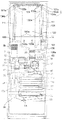
次に、図11は第2実施形態の冷蔵庫を示す正面断面図である。説明の便宜上、前述の図1〜図10に示す第1実施形態と同様の部分には同一の符号を付している。本実施形態は冷蔵室2の背面の冷気通路32が分岐せずに上方に延び、上部で左右に広がる。その他の部分は第1実施形態と同様である。   Next, FIG. 11 is a front sectional view showing the refrigerator of the second embodiment. For convenience of explanation, the same reference numerals are assigned to the same parts as those in the first embodiment shown in FIGS. In the present embodiment, the cold air passage 32 on the back surface of the refrigerator compartment 2 extends upward without branching, and extends to the left and right at the top. Other parts are the same as those in the first embodiment.

ダクト102の背面に突設される突起部102aは中央部に冷気通路32を形成する。突起部102aは冷気通路32の両側方でそれぞれ環状に設けられ、空間部111を形成する。冷気通路32は空間部111の上方で左右に広がり、左右の端部に吐出口104a、104bが形成される。   A protrusion 102a protruding from the rear surface of the duct 102 forms a cold air passage 32 at the center. The protrusions 102 a are provided in an annular shape on both sides of the cold air passage 32 to form a space 111. The cool air passage 32 extends left and right above the space 111, and discharge ports 104a and 104b are formed at the left and right ends.

また、部材101はダクト102の側壁よりも外側を覆い、冷気通路32の周囲に延びて形成される。これにより、第1実施形態と同様に、冷気通路32の流路面積を小さく形成するとともに部材101によって広い範囲から冷熱を冷蔵室2に放出することができる。これにより、冷気の流速の著しい低下を抑制して冷気通路32内を冷気が行き届き、冷熱が冷蔵室2全体に行き届く。従って、冷蔵室2の容積を広くしても温度分布を均一にできる。   The member 101 covers the outer side of the side wall of the duct 102 and extends around the cool air passage 32. Thereby, similarly to 1st Embodiment, the flow-path area of the cold air | gas channel | path 32 can be formed small, and cold heat can be discharge | released to the refrigerator compartment 2 from the wide range by the member 101. FIG. Thereby, the remarkable fall of the flow velocity of cold air is suppressed, cold air reaches the inside of the cold air passage 32, and cold heat reaches the entire refrigerator compartment 2. Therefore, even if the volume of the refrigerator compartment 2 is increased, the temperature distribution can be made uniform.

吐出口104a、104bは冷蔵室2の上部に設けられるため、吐出口104a、104bから吐出された冷気は自重により流下する。これにより、冷蔵室2内に冷気を行き渡らせることができる。   Since the discharge ports 104a and 104b are provided in the upper part of the refrigerator compartment 2, the cold air discharged from the discharge ports 104a and 104b flows down by its own weight. Thereby, cold air can be spread in the refrigerator compartment 2.

次に、図12は第3実施形態の冷蔵庫を示す側面断面図である。説明の便宜上、前述の図1〜図10に示す第1実施形態と同様の部分には同一の符号を付している。本実施形態は冷蔵室送風機23が排気側を後方上方に向けて傾斜して配置されている。その他の部分は第1実施形態と同様である。   Next, FIG. 12 is a side sectional view showing the refrigerator of the third embodiment. For convenience of explanation, the same reference numerals are assigned to the same parts as those in the first embodiment shown in FIGS. In this embodiment, the refrigerating room blower 23 is disposed so that the exhaust side is inclined rearward and upward. Other parts are the same as those in the first embodiment.

本実施形態によると、第1実施形態と同様の効果を得ることができる。また、冷却器11で生成された冷気は冷凍室送風機12により冷気通路31の前部31aに導かれ、冷蔵室ダンパ20を介して冷蔵室送風機23の吸気側に導かれる。冷気通路32は冷蔵室送風機23よりも上方で冷蔵室ダンパ20よりも後方に配置される。   According to this embodiment, the same effect as that of the first embodiment can be obtained. In addition, the cold air generated by the cooler 11 is guided to the front portion 31 a of the cold air passage 31 by the freezer blower 12, and is led to the intake side of the refrigerating room blower 23 through the refrigerating room damper 20. The cold air passage 32 is disposed above the cold room blower 23 and behind the cold room damper 20.

このため、冷蔵室送風機23によって前部31aから冷気がスムーズに冷気通路32へ導かれる。従って、冷気流の渦が発生しにくく圧力損失も小さくなり、送風効率を向上して省エネルギー化を図るとともに騒音の発生を抑えることができる。   For this reason, the cool air is smoothly guided from the front portion 31 a to the cool air passage 32 by the refrigerator compartment fan 23. Therefore, the vortex of the cold airflow is not easily generated, and the pressure loss is also reduced, so that the blowing efficiency can be improved to save energy and the generation of noise can be suppressed.

次に、図13、図14は第4実施形態の冷蔵庫を示す正面図及び右側面断面図である。説明の便宜上、前述の図1〜図10に示す第1実施形態と同様の部分には同一の符号を付している。本実施形態は第1実施形態に対して冷蔵室送風機23(図3参照)が省かれ、冷凍室送風機12及び冷蔵室ダンパ20の配置が異なっている。その他の部分は第1実施形態と同様である。   Next, FIG. 13, FIG. 14 is the front view and right side sectional drawing which show the refrigerator of 4th Embodiment. For convenience of explanation, the same reference numerals are assigned to the same parts as those in the first embodiment shown in FIGS. In the present embodiment, the refrigerator compartment fan 23 (see FIG. 3) is omitted from the first embodiment, and the arrangement of the refrigerator compartment fan 12 and the refrigerator compartment damper 20 is different. Other parts are the same as those in the first embodiment.

冷凍室送風機12は冷蔵庫1本体の右側の端部に配置され、正面投影において断熱壁7と一部が重なり下部が冷凍室6側に延びている。これにより、冷気通路31は冷却器11と冷凍室送風機12との距離が長く、広い空間をとることができる。このため、この空間部分が冷凍室送風機12の吸い込み側の負の圧力室として働き、冷却器11の上部付近において前後方向及び左右方向で冷気流がほぼ均一となる。その結果、冷却器11と熱交換する冷気は前後方向及び左右方向で均一に流通し、冷却器11の熱交換効率が向上する。   The freezer compartment blower 12 is disposed at the right end of the refrigerator 1 main body, and partially overlaps the heat insulating wall 7 in front projection, and the lower portion extends to the freezer compartment 6 side. Thereby, the cool air passage 31 has a long distance between the cooler 11 and the freezer compartment fan 12 and can take a wide space. For this reason, this space part functions as a negative pressure chamber on the suction side of the freezer compartment blower 12, and in the vicinity of the upper portion of the cooler 11, the cold airflow is substantially uniform in the front-rear direction and the left-right direction. As a result, the cool air that exchanges heat with the cooler 11 circulates uniformly in the front-rear direction and the left-right direction, and the heat exchange efficiency of the cooler 11 is improved.

また、冷凍室送風機12は製氷室4上部に配される製氷皿62の後方に配置され、正面の製氷皿62に向けて送風する。このため、製氷皿62に対して充分な冷却を行うことができ、製氷を早く完了させることができる。尚、冷凍室送風機12と製氷皿62の位置関係によっては、製氷皿62の方向に向けて冷凍室送風機12を配置してもよい。例えば、冷凍室送風機12を斜め上向きや斜め下向きに配置してもよく、左右方向に少し傾けて配置してもよい。   Moreover, the freezer compartment fan 12 is arrange | positioned behind the ice-making tray 62 distribute | arranged to the ice-making chamber 4 upper part, and blows it toward the ice-making tray 62 of the front. For this reason, the ice tray 62 can be sufficiently cooled, and the ice making can be completed quickly. Depending on the positional relationship between the freezer blower 12 and the ice tray 62, the freezer blower 12 may be disposed toward the ice tray 62. For example, the freezer compartment fan 12 may be disposed obliquely upward or obliquely downward, or may be disposed slightly inclined in the left-right direction.

また、冷気の吐出し方向を少し左右方向の中央よりに向けるように冷凍室送風機12を配置してもよい。これにより、冷蔵室用ダンパ20や温度切替室吐出ダンパ37への送風効率が向上する。   Moreover, you may arrange | position the freezer compartment fan 12 so that the discharge direction of cold air may face a little from the center of the left-right direction. Thereby, the ventilation efficiency to the refrigerator 20 for refrigerator compartments and the temperature switching chamber discharge damper 37 improves.

冷蔵室ダンパ20は冷凍室送風機12の左方に隣接し、正面投影において断熱壁7と重なって配置される。これにより、製氷室4の奥行を広く確保して容積効率を向上できるとともに、冷蔵室ダンパ20の下方のスペースを広く確保して冷却器11と冷凍室送風機12との距離を容易に長くすることができる。尚、冷蔵室ダンパ20が断熱壁7の上下方向に離れて近設されていてもよい。   The refrigerator compartment damper 20 is adjacent to the left side of the freezer compartment fan 12 and is disposed so as to overlap the heat insulating wall 7 in front projection. Accordingly, the depth of the ice making chamber 4 can be secured widely to improve the volumetric efficiency, and the space below the refrigerator compartment damper 20 can be secured widely to easily increase the distance between the cooler 11 and the freezer compartment fan 12. Can do. It should be noted that the refrigerator compartment damper 20 may be provided close to the heat insulating wall 7 in the vertical direction.

本実施形態によると、第1実施形態と同様の効果を得ることができる。また、冷蔵室2の下方の断熱壁7と冷凍室送風機12とを正面投影において重なる位置に配置したので、冷蔵室2と冷凍室送風機12とが接近して配置される。このため、冷蔵室2の容積が大きくても冷凍室送風機12に近い吐出口と遠い吐出口との間で吐出される冷気流の強さの差が小さくなる。   According to this embodiment, the same effect as that of the first embodiment can be obtained. Moreover, since the heat insulation wall 7 below the refrigerator compartment 2 and the freezer compartment fan 12 are arranged at the overlapping position in the front projection, the refrigerator compartment 2 and the freezer compartment fan 12 are arranged close to each other. For this reason, even if the volume of the refrigerator compartment 2 is large, the difference of the strength of the cold airflow discharged between the discharge port close to the freezer blower 12 and the distant discharge port becomes small.

従って、冷蔵室2の温度分布を更に均一にすることができる。また、冷蔵室2内に冷凍室送風機12が配置されないため、冷蔵室2の容積を広く確保して冷蔵庫1の容積効率を向上することができる。   Therefore, the temperature distribution in the refrigerator compartment 2 can be made more uniform. Moreover, since the freezer compartment fan 12 is not arranged in the refrigerator compartment 2, the volume of the refrigerator compartment 2 can be secured widely and the volume efficiency of the refrigerator 1 can be improved.

第1〜第4実施形態において、野菜室5の流出口にダンパを設けてもよい。これにより、温度切替室3を高温側から低温側に切り替えた際に、該ダンパを閉じて温度切替室3からの熱風が野菜室5に逆流することを防止できる。また、温度切替室3を高温側から低温側へ切り替える際に冷凍室送風機12が停止されている場合には、冷凍室戻り口22が閉じられるように通路開閉機構(例えば、ダンパ)を設けてもよい。これにより、温度切替室送風機18の駆動によって冷凍室戻り口22から冷凍室6内へ熱風が逆流することを防止できる。   In the first to fourth embodiments, a damper may be provided at the outlet of the vegetable compartment 5. Thereby, when the temperature switching chamber 3 is switched from the high temperature side to the low temperature side, it is possible to prevent the hot air from the temperature switching chamber 3 from flowing backward into the vegetable chamber 5 by closing the damper. In addition, when the freezer compartment fan 12 is stopped when the temperature switching chamber 3 is switched from the high temperature side to the low temperature side, a passage opening / closing mechanism (for example, a damper) is provided so that the freezer compartment return port 22 is closed. Also good. Thereby, it is possible to prevent the hot air from flowing backward from the freezer return port 22 into the freezer compartment 6 by driving the temperature switching chamber blower 18.

本発明によると、貯蔵室に冷熱を放出する部材を備えた冷蔵庫に利用することができる。   According to this invention, it can utilize for the refrigerator provided with the member which discharge | releases cold heat in a storage room.

本発明の第1実施形態の冷蔵庫を示す正面図The front view which shows the refrigerator of 1st Embodiment of this invention. 本発明の第1実施形態の冷蔵庫を示す右側面図The right view which shows the refrigerator of 1st Embodiment of this invention. 本発明の第1実施形態の冷蔵庫を示す右側面断面図Sectional drawing on the right side showing the refrigerator according to the first embodiment of the present invention. 本発明の第1実施形態の冷蔵庫を示す正面断面図Front sectional drawing which shows the refrigerator of 1st Embodiment of this invention. 図4のA−A断面図AA sectional view of FIG. 本発明の第1実施形態の冷蔵庫の部材を示す側面断面図Side surface sectional drawing which shows the member of the refrigerator of 1st Embodiment of this invention. 本発明の第1実施形態の冷蔵庫の他の部材を示す上面断面図Top sectional drawing which shows the other member of the refrigerator of 1st Embodiment of this invention. 本発明の第1実施形態の冷蔵庫の他の部材を示す正面図The front view which shows the other member of the refrigerator of 1st Embodiment of this invention. 図8のB−B断面図BB sectional view of FIG. 本発明の第1実施形態の冷蔵庫の冷気の流れを示す冷気回路図The cold air circuit diagram which shows the flow of the cold air of the refrigerator of 1st Embodiment of this invention 本発明の第2実施形態の冷蔵庫を示す正面断面図Front sectional drawing which shows the refrigerator of 2nd Embodiment of this invention. 本発明の第3実施形態の冷蔵庫を示す右側面断面図Sectional drawing on the right side showing the refrigerator of the third embodiment of the present invention 本発明の第4実施形態の冷蔵庫を示す正面断面図Front sectional drawing which shows the refrigerator of 4th Embodiment of this invention. 本発明の第5実施形態の冷蔵庫を示す右側面断面図Sectional drawing of right side which shows the refrigerator of 5th Embodiment of this invention.

符号の説明Explanation of symbols

1 冷蔵庫
2 冷蔵室
3 温度切替室
4 製氷室
5 野菜室
6 冷凍室
7、8、35 断熱壁
11 冷却器
12 冷凍室送風機
15 導入通風路
16 ヒータ
17 戻り通風路
18 温度切替室送風機
20 冷蔵室ダンパ
22 冷凍室戻り口
23 冷蔵室送風機
31、32 冷気通路
32a 第1分岐路
32b 第2分岐路
32c 連結部
36 縦断熱壁
37 温度切替室吐出ダンパ
38 温度切替室戻りダンパ
45 気液分離器
57 圧縮機
100 パネル
101 部材
102 ダクト
102a 突起部
102d 断熱部
103a、103b、104a、104b、105a、105b、105c 吐出口
108 タンク
111 空間部
120 パネル組品
DESCRIPTION OF SYMBOLS 1 Refrigerator 2 Refrigeration room 3 Temperature switching room 4 Ice making room 5 Vegetable room 6 Freezer room 7, 8, 35 Insulation wall 11 Cooler 12 Freezer room blower 15 Introduction ventilation path 16 Heater 17 Return ventilation path 18 Temperature switching room blower 20 Cold storage room Damper 22 Freezer compartment return port 23 Refrigerating room blower 31, 32 Cold air passage 32a First branch passage 32b Second branch passage 32c Connecting portion 36 Vertical heat insulating wall 37 Temperature switching chamber discharge damper 38 Temperature switching chamber return damper 45 Gas-liquid separator 57 Compressor 100 Panel 101 Member 102 Duct 102a Protruding part 102d Heat insulating part 103a, 103b, 104a, 104b, 105a, 105b, 105c Discharge port 108 Tank 111 Space part 120 Panel assembly

Claims (4)

貯蔵物を収納する貯蔵室と、
前記貯蔵室に流入する冷気を生成する冷却器と、
前記貯蔵室の背面に配されて前記冷却器からの冷気が流通する冷気通路と、
前記冷気通路の周囲に延びて前記冷気通路の前面側を覆うとともに前記冷気通路を流通する冷気の冷熱を伝えて前記貯蔵室内に放出する部材と、
冷気が流入する側の前記冷気通路に配される断熱部と、
前記冷気通路を流通する冷気を前記貯蔵室に吐出する吐出口と、
を備え、水平に延びて結露水を溜める凹部を前記部材の表面に設け、
前記凹部は、内面上部に形成されて下方に面する上面部と、内面下部に形成されて上方に面する下面部とを有し、
前記上面部に前記吐出口を形成したことを特徴とする冷蔵庫。
A storage room for storing stored items;
A cooler for generating cold air flowing into the storage chamber;
A cold air passage which is arranged on the back of the storage chamber and through which the cold air from the cooler flows;
A member extending around the cold air passage to cover the front side of the cold air passage and transmitting the cold heat of the cold air flowing through the cold air passage to be discharged into the storage chamber;
A heat insulating portion disposed in the cold air passage on the side where the cold air flows;
A discharge port for discharging cold air flowing through the cold air passage to the storage chamber;
Provided with a recess that extends horizontally and accumulates condensed water on the surface of the member,
The concave portion has an upper surface portion formed on the upper surface of the inner surface and facing downward, and a lower surface portion formed on the lower surface of the inner surface and facing upward.
A refrigerator characterized in that the discharge port is formed in the upper surface portion .
前記上面部は前方へ行くほど上方になるように傾斜していることを特徴とする請求項1に記載の冷蔵庫。 The refrigerator according to claim 1, wherein the upper surface portion is inclined so as to be upward as it goes forward . 前記部材を着脱自在にしたことを特徴とする請求項1または請求項2に記載の冷蔵庫。 The refrigerator according to claim 1 or 2, wherein the member is detachable . 前記部材の少なくとも一部に前記冷気通路を流通する冷気が直接接することを特徴とする請求項1〜請求項3のいずれかに記載の冷蔵庫。The refrigerator according to any one of claims 1 to 3, wherein cold air flowing through the cold air passage is in direct contact with at least a part of the member.
JP2007204505A 2007-08-06 2007-08-06 refrigerator Active JP5254578B2 (en)

Priority Applications (1)

Application Number Priority Date Filing Date Title
JP2007204505A JP5254578B2 (en) 2007-08-06 2007-08-06 refrigerator

Applications Claiming Priority (1)

Application Number Priority Date Filing Date Title
JP2007204505A JP5254578B2 (en) 2007-08-06 2007-08-06 refrigerator

Related Child Applications (2)

Application Number Title Priority Date Filing Date
JP2013086183A Division JP5620538B2 (en) 2013-04-17 2013-04-17 refrigerator
JP2013086182A Division JP5617003B2 (en) 2013-04-17 2013-04-17 refrigerator

Publications (3)

Publication Number Publication Date
JP2009041793A JP2009041793A (en) 2009-02-26
JP2009041793A5 JP2009041793A5 (en) 2010-09-24
JP5254578B2 true JP5254578B2 (en) 2013-08-07

Family

ID=40442717

Family Applications (1)

Application Number Title Priority Date Filing Date
JP2007204505A Active JP5254578B2 (en) 2007-08-06 2007-08-06 refrigerator

Country Status (1)

Country Link
JP (1) JP5254578B2 (en)

Families Citing this family (6)

* Cited by examiner, † Cited by third party
Publication number Priority date Publication date Assignee Title
JP2011064340A (en) * 2009-09-15 2011-03-31 Sharp Corp Refrigerator
JP2017215120A (en) * 2016-06-02 2017-12-07 パナソニックIpマネジメント株式会社 refrigerator
JP6854596B2 (en) * 2016-06-27 2021-04-07 日立グローバルライフソリューションズ株式会社 refrigerator
JP7223581B2 (en) * 2019-01-23 2023-02-16 日立グローバルライフソリューションズ株式会社 refrigerator
JP2020118340A (en) * 2019-01-23 2020-08-06 日立グローバルライフソリューションズ株式会社 refrigerator
JP7028946B2 (en) * 2020-11-17 2022-03-02 日立グローバルライフソリューションズ株式会社 refrigerator

Family Cites Families (8)

* Cited by examiner, † Cited by third party
Publication number Priority date Publication date Assignee Title
JP3611021B2 (en) * 1999-08-31 2005-01-19 シャープ株式会社 refrigerator
JP3652183B2 (en) * 1999-09-28 2005-05-25 シャープ株式会社 refrigerator
JP3644855B2 (en) * 1999-10-06 2005-05-11 シャープ株式会社 refrigerator
JP3714830B2 (en) * 1999-10-07 2005-11-09 シャープ株式会社 refrigerator
JP3644860B2 (en) * 1999-12-10 2005-05-11 シャープ株式会社 refrigerator
JP3582644B2 (en) * 2000-02-04 2004-10-27 シャープ株式会社 refrigerator
JP4642791B2 (en) * 2007-02-14 2011-03-02 シャープ株式会社 refrigerator
JP4896760B2 (en) * 2007-02-14 2012-03-14 シャープ株式会社 refrigerator

Also Published As

Publication number Publication date
JP2009041793A (en) 2009-02-26

Similar Documents

Publication Publication Date Title
JP5254578B2 (en) refrigerator
JP4667307B2 (en) refrigerator
JP4642791B2 (en) refrigerator
JP3714830B2 (en) refrigerator
JP4562763B2 (en) refrigerator
JP4033888B2 (en) refrigerator
JP3647343B2 (en) refrigerator
JP5617003B2 (en) refrigerator
JP5620538B2 (en) refrigerator
JP4111942B2 (en) refrigerator
JP4959474B2 (en) refrigerator
JP2009092340A (en) Refrigerator
JP4896760B2 (en) refrigerator
JP2009068800A (en) Refrigerator
JP4079960B2 (en) refrigerator
JP2009192112A (en) Refrigerator
JP5265237B2 (en) refrigerator
JP5490853B2 (en) refrigerator
JP5133634B2 (en) refrigerator
JP5411922B2 (en) refrigerator
JP5237598B2 (en) refrigerator
JP2009041864A (en) Refrigerator
JP2009121784A (en) Refrigerator
JP2015014452A (en) Refrigerator
JP4746018B2 (en) refrigerator

Legal Events

Date Code Title Description
A521 Written amendment

Free format text: JAPANESE INTERMEDIATE CODE: A523

Effective date: 20100806

A621 Written request for application examination

Free format text: JAPANESE INTERMEDIATE CODE: A621

Effective date: 20100806

A977 Report on retrieval

Free format text: JAPANESE INTERMEDIATE CODE: A971007

Effective date: 20120116

A131 Notification of reasons for refusal

Free format text: JAPANESE INTERMEDIATE CODE: A131

Effective date: 20120131

A521 Written amendment

Free format text: JAPANESE INTERMEDIATE CODE: A523

Effective date: 20120402

A131 Notification of reasons for refusal

Free format text: JAPANESE INTERMEDIATE CODE: A131

Effective date: 20120925

A521 Written amendment

Free format text: JAPANESE INTERMEDIATE CODE: A523

Effective date: 20121122

TRDD Decision of grant or rejection written
A01 Written decision to grant a patent or to grant a registration (utility model)

Free format text: JAPANESE INTERMEDIATE CODE: A01

Effective date: 20130319

A61 First payment of annual fees (during grant procedure)

Free format text: JAPANESE INTERMEDIATE CODE: A61

Effective date: 20130418

R150 Certificate of patent or registration of utility model

Ref document number: 5254578

Country of ref document: JP

Free format text: JAPANESE INTERMEDIATE CODE: R150

Free format text: JAPANESE INTERMEDIATE CODE: R150

FPAY Renewal fee payment (event date is renewal date of database)

Free format text: PAYMENT UNTIL: 20160426

Year of fee payment: 3

S531 Written request for registration of change of domicile

Free format text: JAPANESE INTERMEDIATE CODE: R313531

R350 Written notification of registration of transfer

Free format text: JAPANESE INTERMEDIATE CODE: R350

RD03 Notification of appointment of power of attorney

Free format text: JAPANESE INTERMEDIATE CODE: R3D03