RU2215879C2 - Piston machine (versions) - Google Patents
Piston machine (versions) Download PDFInfo
- Publication number
- RU2215879C2 RU2215879C2 RU2000115856/06A RU2000115856A RU2215879C2 RU 2215879 C2 RU2215879 C2 RU 2215879C2 RU 2000115856/06 A RU2000115856/06 A RU 2000115856/06A RU 2000115856 A RU2000115856 A RU 2000115856A RU 2215879 C2 RU2215879 C2 RU 2215879C2
- Authority
- RU
- Russia
- Prior art keywords
- cylinder
- cylinders
- pistons
- inlet
- windows
- Prior art date
Links
Images


Abstract
Description
Изобретение относится к машиностроению, в частности к конструкции поршневых двухтактных и четырехтактных двигателей внутреннего сгорания, а также к конструкции поршневых компрессоров и насосов, которые имеют механизм движения поршней и рабочий цилиндр с впускными и выпускными окнами. The invention relates to mechanical engineering, in particular to the design of reciprocating two-stroke and four-stroke internal combustion engines, as well as to the design of reciprocating compressors and pumps, which have a piston movement mechanism and a working cylinder with inlet and outlet windows.
В качестве группы изобретений предлагается несколько независимых вариантов исполнения поршневой машины, которая может быть использована по различному назначению с сохранением основных отличительных особенностей. Все варианты поршневой машины имеют один вид и обеспечивают получение сходного технического результата, т.к. обеспечивают сжатие газа или перекачку жидкой среды с помощью поступательного движения поршней и работы распределительного механизма. As a group of inventions, several independent piston engine versions are proposed, which can be used for various purposes while maintaining the main distinguishing features. All variants of the piston machine have one look and provide a similar technical result, because provide gas compression or pumping a liquid medium using the translational movement of the pistons and the operation of the distribution mechanism.
В качестве ближайшего прототипа для поршневой машины, имеющей цилиндр, поршень, впускные и выпускные окна, а также устройство для перекрытия окон, может быть принята поршневая машина, имеющая эти же ограничительные признаки. К такой поршневой машине можно отнести четырехтактные и двухтактные двигатели внутреннего сгорания, а также компрессоры для сжатия и отсоса газов (вакуумные компрессоры) и поршневые насосы для перекачки жидких сред. As the closest prototype for a piston machine having a cylinder, a piston, inlet and outlet windows, and also a device for closing the windows, a piston machine having the same limiting features can be adopted. Such a piston machine can include four-stroke and two-stroke internal combustion engines, as well as compressors for compressing and suctioning gases (vacuum compressors) and piston pumps for pumping liquid media.
Все перечисленные известные варианты поршневой машины имеют сложный механизм газораспределения с рядом недостатков, которые снижают технико-экономические показатели поршневой машины. Так, например, у четырехтактного двигателя механизм газораспределения включает в себя подъемные клапаны принудительного действия и кулачковый вал. Подъемные клапаны и кулачковый вал имеют неуравновешенные инерционные массы, которые ограничивают скорость вращения вала двигателя и не позволяют развить его возможную максимальную мощность. Наличие клапанных тарелок, перекрывающих окна, не обеспечивает их полное открытие и увеличивает сопротивление газового тракта. Для уменьшения сопротивления газового тракта иногда используют несколько подъемных клапанов для одного цилиндра, но это значительно усложняет конструкции двигателя. All of the known variants of the piston engine listed above have a complex gas distribution mechanism with a number of disadvantages that reduce the technical and economic performance of the piston engine. So, for example, in a four-stroke engine, the gas distribution mechanism includes forced-lift valves and a cam shaft. The lifting valves and the camshaft have unbalanced inertial masses that limit the rotation speed of the motor shaft and prevent it from developing its maximum possible power. The presence of valve plates overlapping the windows does not ensure their full opening and increases the resistance of the gas path. To reduce the resistance of the gas path, sometimes several lift valves are used for one cylinder, but this greatly complicates the design of the engine.
Газораспределительный механизм, имеющий кулачковый распредвал, клапаны, толкатели, подвержен быстрому износу, имеет низкий механический кпд и повышенный уровень шума. По мере износа кулачков распредвала и толкателей требуется периодическая регулировка зазоров в процессе эксплуатации. A gas distribution mechanism having a camshaft, valves, pushers, is subject to rapid wear, has a low mechanical efficiency and an increased noise level. As the camshafts and cam followers wear out, periodic clearance adjustment is required during operation.
В поршневых компрессорах и насосах в качестве распределительного механизма используются подъемные самодействующие клапаны, запорные элементы которых также имеют неуравновешенные инерционные массы. Поэтому самодействующие клапаны имеют низкую надежность и не позволяют увеличить скорость вращения поршневой машины. In reciprocating compressors and pumps, self-acting lifting valves are used as a distribution mechanism, the shut-off elements of which also have unbalanced inertial masses. Therefore, self-acting valves have low reliability and do not allow to increase the speed of rotation of the piston machine.
В двухтактных двигателях внутреннего сгорания в качестве распределительного механизма используются выполненные на стенке цилиндра окна, которые перекрываются поршнем. Такое расположение окон влечет за собой необходимость увеличения длины цилиндров и поршней. При малой длине цилиндров и поршней возникает вероятность выноса масла из картера двигателя в выпускные окна и попадания топлива в картер двигателя через впускные окна. Кроме того, по этой причине необходимо размещать дополнительные поршневые кольца на нижней части юбки поршня. In two-stroke internal combustion engines, windows made on the cylinder wall, which are overlapped by a piston, are used as a distribution mechanism. This arrangement of windows entails the need to increase the length of the cylinders and pistons. If the length of the cylinders and pistons is short, there is a chance that the oil will escape from the crankcase into the exhaust ports and fuel will enter the crankcase through the intake ports. In addition, for this reason, it is necessary to place additional piston rings on the bottom of the piston skirt.
Задачей изобретения является повышение технико-экономических показателей поршневой машины за счет упрощения и повышения надежности распределительного механизма у машин, сжимающих газ или перекачивающих жидкость. The objective of the invention is to increase the technical and economic indicators of a piston machine by simplifying and increasing the reliability of the distribution mechanism of machines that compress gas or pump liquid.
В качестве ближайшего прототипа можно принять конструкцию поршневой машины, используемой в качестве двигателя-компрессора, которая описана в книге [2]. As the closest prototype, we can take the design of the piston machine used as an engine-compressor, which is described in the book [2].
Недостатком известной машины является малая эффективность ее работы. A disadvantage of the known machine is the low efficiency of its work.
Техническим результатом для всех вариантов является повышение эффективности. The technical result for all options is to increase efficiency.
Поставленная задача в части первого варианта достигается тем, что поршневая машина, например, как двухтактный или четырехтактный двигатель внутреннего сгорания, компрессор для сжатия или отсоса газа или насос для перекачки жидкой среды, содержащая цилиндры с полостями, в которых перемещаются поршни, камеру впуска и камеру выпуска, в которых вращаются цилиндрические золотники, связанные с валом двигателя, и впускные и выпускные окна, соединенные перепускными каналами с камерами впуска и выпуска, согласно изобретению содержит как минимум два цилиндра, впускная камера расположена над одним цилиндром, а выпускная - над другим, при этом каждая камера работает на два цилиндра. The task in part of the first embodiment is achieved by the fact that the piston machine, for example, as a two-stroke or four-stroke internal combustion engine, a compressor for compressing or sucking gas or a pump for pumping a liquid medium containing cylinders with cavities in which the pistons, the intake chamber and the chamber move of the outlet, in which the cylindrical spools connected with the motor shaft rotate, and the inlet and outlet windows connected by the bypass channels to the intake and exhaust chambers, according to the invention, contains at least two cylinders, the inlet chamber is located above one cylinder, and the exhaust chamber is above the other, with each chamber working on two cylinders.
Поставленная задача достигается также тем, что полости цилиндров могут быть соединены между собой при помощи канала с образованием общей камеры сгорания для двух цилиндров, а поршни совершают движение в одном направлении, при этом один цилиндр имеет впускные окна, а другой цилиндр - выпускные окна, либо цилиндры работают независимо друг от друга, поршни цилиндров совершают встречное движение и работают в противофазе, в камерах впуска и выпуска размещены по два золотника, а каждый цилиндр имеет и впускное и выпускное окно. The task is also achieved by the fact that the cavity of the cylinders can be interconnected using a channel with the formation of a common combustion chamber for two cylinders, and the pistons move in one direction, while one cylinder has inlet windows and the other cylinder has outlet windows, or the cylinders operate independently of each other, the pistons of the cylinders counter-move and work in antiphase, two spools are placed in the intake and exhaust chambers, and each cylinder has an inlet and an outlet window.
Поставленная задача в части второго варианта достигается тем, что в поршневой машине, содержащей как минимум два смежных рабочих цилиндра с рабочими полостями, в которых перемещаются поршни, связанные каждый со своим кривошипом, камеры впуска и камеры выпуска, в которых перемещаются золотники, связанные с поршнями, впускные и выпускные окна, выполненные в рабочих цилиндрах над поршнями при их положении в верхней мертвой точке и соединенные перепускными каналами с окнами камеры впуска и камеры выпуска, согласно изобретению, золотники связаны с поршнями при помощи штоков, а камеры установлены над рабочими поршнями через разделяющую перегородку. The task in part of the second option is achieved by the fact that in a piston machine containing at least two adjacent working cylinders with working cavities in which pistons are moved, each connected with its crank, intake chambers and exhaust chambers in which spools connected with pistons are moved , inlet and outlet windows made in the working cylinders above the pistons at their position at top dead center and connected bypass channels with the windows of the intake chamber and exhaust chamber, according to the invention, anes to the pistons by means of rods, a camera installed above the working piston through the separating partition.
Поставленная задача достигается также тем, что рабочие полости могут быть соединены между собой при помощи канала с образованием общей камеры сгорания для двух рабочих цилиндров, поршни совершают движение в одном направлении, при этом один цилиндр имеет впускные окна, а другой цилиндр - выпускные окна, либо цилиндры являются независимыми, рабочие поршни совершают встречное движение и работают в противофазе, при этом каждый цилиндр имеет впускные и выпускные окна. The task is also achieved by the fact that the working cavities can be interconnected using a channel with the formation of a common combustion chamber for two working cylinders, the pistons move in one direction, while one cylinder has inlet windows and the other cylinder has outlet windows, or the cylinders are independent, the working pistons counter-move and work in antiphase, with each cylinder having inlet and outlet windows.
Поставленная задача достигается также тем, что золотники могут быть выполнены прямоугольного сечения. The task is also achieved by the fact that the spools can be made of rectangular cross-section.
Поставленная задача в части третьего варианта достигается тем, что в поршневой машине, содержащей цилиндры, расположенные через разделяющую перегородку один над другим, у которых поршни цилиндров первого ряда связаны штоками с поршнями цилиндров второго ряда, а рабочий цилиндр выполнен сдвоенным и имеет впускные и выпускные окна и общую камеру сгорания, сообщающую его рабочие полости, которые расположены по обе стороны перегородки, согласно изобретению рабочие полости цилиндров первого ряда выполнены проточными и соединены со стороны входа и выхода газа с рабочими полостями цилиндров второго ряда, а впускные и выпускные окна цилиндров первого ряда выполнены в верхней части цилиндра над поршнем при его положении в верхней мертвой точке. The task in part of the third option is achieved by the fact that in a piston machine containing cylinders located through a separating partition one above the other, in which the pistons of the cylinders of the first row are connected by rods to the pistons of the cylinders of the second row, and the working cylinder is doubled and has inlet and outlet windows and a common combustion chamber communicating its working cavities, which are located on both sides of the partition, according to the invention, the working cavities of the cylinders of the first row are flow-through and connected from the side gas inlet and outlet with working cavities of the second row cylinders, and the inlet and outlet windows of the first row cylinders are made in the upper part of the cylinder above the piston at its position at top dead center.
Поршневая машина в варианте выполнения по пунктам 1 и 2 формулы изобретения поясняется на фиг. 1-5 и имеет следующий перечень позиций:
1 - сдвоенный рабочий цилиндр;
2 - поршень левого цилиндра;
3 - поршень правого цилиндра;
4 - полость левого цилиндра;
5 - полость правого цилиндра;
6 - канал, соединяющий полости 4 и 5;
7 - впускное окно цилиндра 1;
8 - выпускное окно цилиндра I;
9 - камера впуска;
10 - камера выпуска;
11 - перегородка, разделяющая камеры;
12 - сальник перегородки;
13 - распределительный вал;
14 - подшипники вала 12;
15 - приводной шкив вала 12;
16 - золотниковый клапан камеры впуска;
17 - золотниковый клапан камеры выпуска;
18 - выпускное окно золотника 16;
19 - впускное окно золотника 17;
20 - прижимное седло золотника 16;
21 - окно седла 20;
22 - прижимное седло золотника 17;
23 - окно седла 22;
24 - упругая поджимная подушка седел 20 и 22;
25 - перепускной канал из камеры 9 в полость 5;
26 - перепускной канал из полости 4 в камеру 10;
27 - свеча зажигания или форсунка;
28 - нагнетатель;
29 - впускное окно камеры впуска;
30 - выпускное окно камеры выпуска;
31 - коленвал двигателя;
32 - кривошип;
33 - маслозаполненный картер механизма движения.The piston machine in the embodiment of
1 - dual slave cylinder;
2 - the piston of the left cylinder;
3 - the piston of the right cylinder;
4 - cavity of the left cylinder;
5 - cavity of the right cylinder;
6 - channel connecting the
7 - inlet window of
8 - exhaust window of cylinder I;
9 - intake chamber;
10 - exhaust chamber;
11 - a partition separating the chambers;
12 - the seal of the septum;
13 - a camshaft;
14 -
15 - a drive pulley of a
16 - spool valve of the intake chamber;
17 - spool valve of the exhaust chamber;
18 - the outlet window of the
19 - inlet window of the
20 - pressure seat of the
21 - a window of a
22 - pressure seat of the
23 - a
24 - elastic cushion cushion saddles 20 and 22;
25 - bypass channel from the
26 - bypass channel from the
27 - spark plug or nozzle;
28 - supercharger;
29 - inlet window of the intake chamber;
30 - exhaust window of the exhaust chamber;
31 - engine crankshaft;
32 - crank;
33 - oil-filled crankcase of the movement mechanism.
Двигатель имеет минимум два смежных взаимосвязанных рабочих цилиндра с общей камерой сгорания, у которых один цилиндр имеет впускные окна, а другой цилиндр имеет выпускные окна. Поршни цилиндров совершают движение в одном направлении. Принцип работы многоцилиндрового двигателя с четным количеством цилиндров не будет отличаться от двигателя, имеющего два смежных взаимосвязанных цилиндра, а поэтому для рассмотрения предложен двухцилиндровый двигатель. The engine has at least two adjacent interconnected working cylinders with a common combustion chamber, in which one cylinder has inlet windows and the other cylinder has outlet windows. Cylinder pistons move in one direction. The principle of operation of a multi-cylinder engine with an even number of cylinders will not differ from an engine having two adjacent interconnected cylinders, and therefore a two-cylinder engine is proposed for consideration.
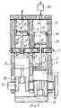
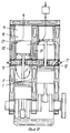
Двигатель, показанный на фиг. 1, имеет два смежных взаимосвязанных цилиндра 1, в которых перемещаются поршни 2 и 3. Над поршнями 2 и 3 образованы полости 4 и 5 рабочих цилиндров, которые соединены между собой каналом 6. Два смежных соединенных между собой цилиндра можно рассматривать как один сдвоенный цилиндр, который имеет общую камеру сгорания и одну на два цилиндра свечу зажигания или форсунку для впрыска топлива 27. Двигатель имеет одну камеру впуска 9 и одну камеру выпуска 10. Через камеры 9 и 10 проходит проводной вал 13, установленный в подшипниках 14. На валу 13 жестко закреплены шкив 15, взаимодействующий с зубчатым ремнем или цепью, а также золотник 16 камеры впуска и золотник 17 камеры выпуска. На цилиндрической поверхности золотника 16 выполнено окно 18, а на поверхности золотника 17 - окно 19. К цилиндрической поверхности золотника 16 прижато седло 20, имеющее окно 21, а к цилиндрической поверхности золотника 17 прижато седло 22, имеющее окно 23. Прижатие седел 20 и 22 к золотникам 16 и 17 осуществляется упругими подушками или обычными подпружиненными подушками. Конструктивное выполнение поджимных седел может быть различным. В частности, седла могут быть выполнены из антифрикционных материалов, не требующих смазки, например на основе графитофторопласта. Камера впуска 9 имеет впускное окно 29, а камера выпуска 10 имеет выпускное окно 30. К камере впуска может быть подключен нагнетатель 28. К цилиндру 5 в варианте использования поршневой машины в качестве двигателя внутреннего сгорания подключена свеча зажигания 27 или форсунка для впрыска топлива. The engine shown in FIG. 1 has two adjacent
Если бы цилиндры были не сдвоенными, пришлось бы иметь на каждый цилиндр одну камеру впуска и одну камеру выпуска. Соответственно на два цилиндра потребовалось бы использовать две камеры впуска и две камеры выпуска. Кроме того, помимо уменьшения количества камер сдвоенный цилиндр позволяет улучшить условия продувки двухтактного двигателя. If the cylinders were not dual, one would have to have one inlet chamber and one exhaust chamber for each cylinder. Accordingly, two inlet chambers and two exhaust chambers would be required for two cylinders. In addition, in addition to reducing the number of chambers, a twin cylinder improves the purge conditions of a two-stroke engine.
Принцип работы двигателя, показанного на фиг. 1: в результате вращения золотниковых клапанов обеспечивается периодическое совмещение окон 18 и 19 золотниковых клапанов соответственно с окнами 7 и 8 цилиндра 1. В зависимости от длины окон 18 и 19 по дуге окружности золотников и их размещения на цилиндрической поверхности золотников по углу поворота вала может быть реализована заданная диаграмма распределения жидкости или газа в зависимости от назначения поршневой машины. The principle of operation of the engine shown in FIG. 1: as a result of the rotation of the slide valves, the
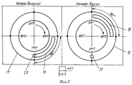
Диаграммы фаз распределения жидкой или газообразной среды в зависимости от назначения поршневой машины показаны на фиг. 2, 3, 4 и 5. The phase diagrams of the distribution of a liquid or gaseous medium depending on the purpose of the piston machine are shown in FIG. 2, 3, 4 and 5.
Вариант четырехтактного двигателя имеет диаграмму газораспределения, показанную на фиг. 2. The four stroke engine variant has a timing diagram shown in FIG. 2.
Четырехтактный двигатель характеризуется тем, что у него полный цикл работы происходит за два оборота вала двигателя. Поэтому передаточное отношение по вращению от вала двигателя к валу газораспределительного механизма устанавливается как два к одному. Соответственно за два оборота вала золотниковые клапаны совершают один оборот. На диаграмме фаз газораспределения видно, что за один оборот золотника поршень два раза подходит к ВМТ и НМТ, а поворот вала двигателя на 180o соответствует повороту золотникового клапана на 90o. Показанное на фиг. 2 положение золотниковых клапанов по углу поворота вала соответствует положению поршня в НМТ. Вращение золотниковых клапанов происходит по часовой стрелке.A four-stroke engine is characterized by the fact that it has a full cycle of work in two revolutions of the engine shaft. Therefore, the gear ratio for rotation from the engine shaft to the camshaft is set to two to one. Accordingly, in two turns of the shaft, the spool valves make one revolution. The diagram of the valve timing shows that for one revolution of the spool the piston twice approaches the TDC and BDC, and a 180 o rotation of the engine shaft corresponds to a 90 o rotation of the spool valve. Shown in FIG. 2, the position of the slide valves in the angle of rotation of the shaft corresponds to the position of the piston in the BDC. Spool valves rotate clockwise.
При переходе поршня от НМТ к ВМТ в камере выпуска происходит совмещение окна 20 седла с окном 16 золотника, которое имеет длину по дуге окружности 90o. Это значит, что при проходе поршня от НМТ к ВМТ газ на всем ходе поршня поступает из полости цилиндра в камеру выпуска 8, а затем через окно 27 идет на выхлоп, т. е. происходит полная очистка цилиндра 1 от сгоревших газов. Одновременно золотник 13 камеры впуска 8 поворачивается на 90o. При подходе поршня к ВМТ происходит закрытие окна 20 и прекращается выпуск газа из цилиндра. К этому моменту в камере впуска 7 окно 13 золотника 13 подходит к окну 18 седла 17. Происходит совмещение окон и при ходе поршня от ВМТ к НМТ осуществляется цикл всасывания, и газ из атмосферы или от нагнетателя 25 через окно 29 поступает в камеру впуска 7, а затем через окна 18 и 21, через канал 25 и окно 7 поступает в цилиндр 1. Цикл всасывания в цилиндр происходит на всем ходе поршня от ВМТ к НМТ, т.к. окно 18 имеет длину по дуге окружности золотника 90o. При подходе поршня к НМТ окна 18 и 21 закрываются. Далее при ходе поршня от НМТ к ВМT происходит сжатие газа в цилиндре, т.к. все окна в цилиндре на этом ходе поршня находятся в закрытом состояние. В ВМТ поршня происходит принудительное воспламенение топливной смеси от свечи зажигания 27 или самовоспламенение при подаче топлива через форсунку 27. Газ при сгорании расширяется и происходит рабочий ход поршня от ВМТ к НМТ. При положении поршня в НМТ или несколько раньше совмещаются отверстия 19 и 23 в камере выпуска, и происходит выхлоп из цилиндра сгоревших газов и начинается очистка цилиндра за счет движения поршня от НМТ к ВМТ. Далее все циклы работы четырехтактного двигателя повторяются.When the piston moves from BDC to BDC in the exhaust chamber, the
На фиг. 3 показана диаграмма фаз газораспределения при использовании поршневой машины в качестве двухтактного двигателя внутреннего сгорания (ДДВС). У ДДВС полный цикл работы происходит за один оборот вала двигателя. Поэтому вал двигателя и золотниковые клапаны должны вращаться синхронно. Рассматривается вариант, когда вращение вала двигателя идет по часовой стрелке. Показанное на фиг. 3 положение золотниковых клапанов по углу поворота вала соответствует положению поршня в HМT. In FIG. 3 shows a valve timing diagram when using a piston engine as a two-stroke internal combustion engine (ICE). At ДДВС the full cycle of work occurs for one revolution of a shaft of the engine. Therefore, the motor shaft and spool valves must rotate synchronously. The option is considered when the rotation of the motor shaft is clockwise. Shown in FIG. 3, the position of the slide valves in the angle of rotation of the shaft corresponds to the position of the piston in the HMT.
Из диаграммы видно, что в этом положении поршня окно 19 седла камеры выпуска открыто и продолжается выпуск из цилиндра сгоревших газов. При этом, т. к. общая длина окна 19 по дуге окружности на цилиндрической поверхности золотника 17 равна α1+α2, из диаграммы видно, что выпуск выхлопных газов из цилиндра начался раньше до подхода поршня к НМТ на угол поворота вала α2. После поворота вала золотникового клапана 17 на угол α1 окно 21 седла 20 камеры впуска еще закрыто. При дальнейшем повороте золотникового клапана 17 на угол α2, а золотникового клапана 16 на угол α3 окна 23 и 21 будут открыты, и будет происходить продувка цилиндра свежим газом. После поворота золотникового клапана 17 на угол α2, а золотникового клапана 16 на угол α3 окно 23 закроется, выпуск газа из цилиндра прекратится и начнется заполнение цилиндра через окно 21 с избыточным давлением газа, которое может создать нагнетатель 28. Продолжительность заполнения цилиндра с избыточным давлением будет соответствовать времени поворота золотникового клапана 16 на угол α4. Такое чередование открытия и закрытия впускных 21 и выпускных окон 23 позволяет обеспечить эффективную прямоточную продувку цилиндра в направление стрелки на фиг. 3 и осуществить заполнение цилиндра после закрытия окна 23 с избыточным давлением.The diagram shows that in this position of the piston, the
После заполнения цилиндра свежей порцией газа поршень продолжает движение от НМТ к ВМТ при закрытых окнах 21 и 23 и происходит процесс сжатия. В ВМТ происходит принудительное зажигание рабочей смеси от свечи или самовоспламенение при дизельном варианте и начинается расширение газа и рабочий ход поршня до начала открытия окна 23. Затем идет выпуск сгоревших газов продувка цилиндра и заполнение его с избыточным давлением, и процесс работы ДДВС повторяется. After filling the cylinder with a fresh portion of gas, the piston continues to move from BDC to TDC with
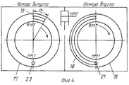
На фиг. 4 показана диаграмма фаз газораспределения в случае использования поршневой машины в качестве поршневого компрессора (ПК) для сжатия газа или для отсоса газа и создания в системе вакуума (вакуумный компрессор). In FIG. 4 shows a gas distribution phase diagram in the case of using a piston machine as a reciprocating compressor (PC) to compress gas or to suck out gas and create a vacuum in the system (vacuum compressor).
Полный цикл работы ПК происходит за один оборот его вала. Поэтому вал ПК и золотниковые клапаны должны вращаться синхронно, для чего передаточное отношение по вращению от вала ПК к валу золотниковых клапанов принимается один к одному. Рассматривается вариант, когда вращение вала идет в направлении часовой стрелки. Показанное на фиг.4 положение золотниковых клапанов по углу поворота вала соответствует положению поршня в НМТ. Из диаграммы видно, что в этом положении золотниковых клапанов окна 21 и 18 закрыты. При движении поршня от НМТ к ВМТ и повороте золотникового клапана 16 на 1800 окно 21 остается закрытым на всем ходе поршня. При повороте золотникового клапана 17 окно 23 остается закрытым до тех пор, пока не начнется совмещение окон 19 и 23. За это время золотниковый клапан 17 повернется на угол 180-α°. В это время поршень идет к ВМТ и сжимает газ в цилиндре 1 на расчетную величину. Т. е. происходит процесс предварительного сжатия газа по принципу, который используется, например, в винтовых компрессорах. Величина предварительного сжатия является расчетной и выбирается такой, чтобы она соответствовала заданному давлению в системе, на которую будет работать ПК.The full cycle of the PC occurs in one revolution of its shaft. Therefore, the PC shaft and spool valves must rotate synchronously, for which the gear ratio for rotation from the PC shaft to the spool valve shaft is taken one to one. The option is considered when the rotation of the shaft is in the clockwise direction. Shown in figure 4, the position of the slide valves in the angle of rotation of the shaft corresponds to the position of the piston in the BDC. The diagram shows that in this position of the spool valves, the
Величина предварительного сжатия является функцией степени сжатия газа, которая будет создана в цилиндре до открытия выпускного окна 23. При повороте золотникового клапана 17 на угол больше, чем 180-α°, начнется совмещение окон 19 и 23, и сжатый газ начнет выталкиваться в камеру выпуска и далее в систему, где должно быть такое же расчетное давление. Длительность выталкивания будет соответствовать времени поворота золотника 17 на угол α°, когда окно 23 закроется цилиндрической поверхностью золотникового клапана 17. Выталкивание сжатого газа из цилиндра закончится при подходе поршня к ВМТ. К этому моменту окно 18 золотникового клапана 16 подойдет к окну 21 и при движении поршня от ВМТ к НМТ начинается процесс всасывания газа в цилиндр, который будет продолжаться на всем ходе поршня до прихода его в НМТ. За это время золотниковый клапан 16 повернется на 180o. После окончания цикла всасывания окно 21 закроется и поршень из НМТ пойдет к ВМТ, т.е. начнется сжатие газа, и весь цикл работы ПК будет повторяться.The amount of pre-compression is a function of the degree of compression of the gas that will be created in the cylinder before opening the
В случае подключения к камере впуска 9 нагнетателя 28 производительность компрессора может быть поднята на величину, пропорциональную величине избыточного давления, которое будет создано перед впускным окном 7 цилиндра 1. In the case of connecting to the
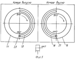
На фиг.5 показана диаграмма фаз распределения в случае использования поршневой машины в качестве поршневого насоса для перекачки жидкой несжимаемой среды. Полный цикл работы ПН происходит за один оборот его вала. Поэтому вал ПН и золотниковые клапаны должны вращаться синхронно, для чего передаточное отношение по вращению вала ПН к валу золотниковых клапанов принимается один к одному. Рассматривается вариант, когда вращение вала идет в направление часовой стрелки. Показанное на фиг.5 положение золотниковых клапанов по углу поворота вала соответствует положению поршня в НМТ. Figure 5 shows a phase diagram of the distribution in the case of using a piston machine as a piston pump for pumping a liquid incompressible medium. The full cycle of operation of the monopole occurs in one revolution of its shaft. Therefore, the PN shaft and slide valves must rotate synchronously, for which the gear ratio for the rotation of the PN shaft to the shaft of the slide valves is taken one to one. The option is considered when the rotation of the shaft is in the clockwise direction. Shown in figure 5, the position of the slide valves in the angle of rotation of the shaft corresponds to the position of the piston in the BDC.
Из диаграммы видно, что в этом положении поршня заканчивается открытие окна 21, т. е. закончится всасывание жидкой среды в цилиндр 1 и начинает открываться окно 23, а это значит, что начинается цикл выталкивания среды из цилиндра 1 в камеру выпуска 10. Дуга окружности окна 18 золотникового клапана 16 камеры впуска 9 и дуга окружности окна 19 золотникового клапана 17 камеры выпуска 10 равны 1800. Поэтому впуск жидкой среды в цилиндр 1 идет на всем насосном ходе поршня при его движении от ВМТ к НМТ.The diagram shows that in this position of the piston the opening of the
Также выпуск жидкой среды из цилиндра 1 идет на всем выталкивающем ходе поршня при его движении от НМТ к ВМТ. Also, the release of liquid medium from
Предложенные варианты поршневой машины, которая может работать в качестве четырехтактного или двухтактного двигателя внутреннего сгорания, а также компрессора для сжатия газа или насоса для перекачки жидкой среды, имеют новую конструкцию распределительного механизма. The proposed piston engine, which can operate as a four-stroke or two-stroke internal combustion engine, as well as a compressor for compressing gas or a pump for pumping a liquid medium, have a new design of the distribution mechanism.
Если сравнивать предложенную поршневую машину в варианте четырехтактного двигателя с уже известными четырехтактными двигателями, у которых распределительный механизм включает в себя кулачковый распредвал, коромысла, подъемные клапаны, сальники и пружины, то можно отметить следующие преимущества предлагаемой конструкции:
- повышается надежность и долговечность, т.к. отсутствует кулачковый распредвал сложной формы, который испытывает динамические пульсирующие нагрузки, подвержен износу и требует обильной смазки;
- инерционные клапаны подъемного типа заменены безынерционными золотниковыми клапанами вращательного действия. В результате может быть увеличена скорость вращения двигателя и уменьшена его масса при заданной мощности;
- снижен уровень шума газораспределительного механизма, т.к. он не испытывает динамических нагрузок из-за отсутствия кулачков и не требуется регулировка зазоров между клапанами и толкателями для компенсации величины износа трущихся поверхностей в процессе эксплуатации;
- золотниковый клапан находится в более легких условиях работы и не требует притирки в процессе эксплуатации, т.к. седло является самоподжимным;
- на привод золотниковых клапанов требуются меньшие затраты энергии, чем на привод подъемных клапанов с использованием кулачкового вала;
- золотниковый клапан является полнопроходным и имеет меньшее газодинамическое сопротивление. Для полного открытия впускных и выпускных окон требуется меньший угол поворота вала, т.е. на всем цикле срабатывания они полностью открыты, а поэтому увеличиваются коэффициент заполнения цилиндра и мощность двигателя;
- меньше вспомогательных деталей типа сальников, пружин.If we compare the proposed piston engine in the variant of a four-stroke engine with the already known four-stroke engines, in which the distribution mechanism includes cam camshaft, rocker arms, lifting valves, oil seals and springs, then the following advantages of the proposed design can be noted:
- increased reliability and durability, because there is no camshaft of complex shape, which experiences dynamic pulsating loads, is subject to wear and requires heavy lubrication;
- inertial valves of the lifting type are replaced by inertialess spool valves of rotational action. As a result, the engine speed can be increased and its mass reduced at a given power;
- reduced noise level of the gas distribution mechanism, as it does not experience dynamic loads due to the lack of cams and does not require adjustment of the gaps between the valves and pushers to compensate for the wear of rubbing surfaces during operation;
- the spool valve is in lighter operating conditions and does not require lapping during operation, as the saddle is self-gripping;
- lower energy costs are required to drive spool valves than to drive lift valves using a cam shaft;
- the spool valve is full bore and has less gas-dynamic resistance. To fully open the inlet and outlet windows, a smaller angle of rotation of the shaft is required, i.e. on the whole cycle of operation they are completely open, and therefore the cylinder filling factor and engine power increase;
- less auxiliary parts such as seals, springs.
Если сравнивать предложенную поршневую машину в варианте двухтактного двигателя с известными двухтактными двигателями, то можно отменить следующие преимущества:
- после продувки цилиндра его заполнение производится при закрытых выпускных окнах, что позволяет при использовании надува получить коэффициент заполнения цилиндра больше единицы. В результате повышаются кпд и мощность двигателя;
- на стенке цилиндра в нижней его части отсутствуют впускные и выпускные окна. В результате исключается унос картерного масла через окна, отпадает необходимость увеличения длины поршней и цилиндров. Могут быть использованы типовые блоки цилиндров и поршни от любого четырехтактного двигателя;
- улучшается схема продувки цилиндра от остаточных газов, что повышает частоту выхлопных газов и экономичность двигателя;
- уменьшается износ поршневых колец, т.к. они не перебегают впускные и выпускные окна, не требуется специальная фиксация поршневых колец на поршне от проворачивания;
- четырехтактные двигатели могут переводиться на двухтактный цикл работы с минимальными затратами, т.к. остается без изменения конструкция блока цилиндров и поршней. Меняется только крышка цилиндра. При этом мощность двигателя увеличивается в два и более раз.If we compare the proposed piston engine in the variant of a two-stroke engine with the known two-stroke engines, then the following advantages can be canceled:
- after purging the cylinder, it is filled with the exhaust windows closed, which allows using the charge to obtain a cylinder fill factor of more than one. As a result, the efficiency and engine power increase;
- on the cylinder wall in its lower part there are no inlet and outlet windows. As a result, the removal of crankcase oil through the windows is eliminated, there is no need to increase the length of the pistons and cylinders. Typical cylinder blocks and pistons from any four-stroke engine can be used;
- improves the scheme of purging the cylinder from residual gases, which increases the frequency of exhaust gases and engine efficiency;
- reduced wear of the piston rings, because they do not run across the inlet and outlet windows; special fixing of the piston rings on the piston from turning is not required;
- four-stroke engines can be transferred to a two-stroke cycle with minimal cost, because the design of the cylinder block and pistons remains unchanged. Only the cylinder cover changes. In this case, engine power is increased by two or more times.
Если сравнивать предложенную поршневую машину в варианте компрессора с известными поршневыми компрессорами, то можно отметить следующие преимущества:
- отсутствуют подъемные самодействующие клапаны с инерционными рабочими пластинами, которые по условиям надежности ограничивают скорость вращения компрессора. Предложенный вариант компрессора имеет безынерционные золотниковые клапаны и позволяет на порядок поднять скорость вращения компрессора, а следовательно, в несколько раз снизить его стоимость и массу при заданной производительности;
- отсутствие самодействующих клапанов, имеющих ударные рабочие пластины, позволяет намного снизить уровень шума работы компрессора;
- снижается сопротивление газового тракта, т.к. впускные и выпускные окна являются полнопроходными на всем цикле их открытия, что улучшает экономические показатели компрессора;
- отсутствие самодействующих клапанов с рабочими пластинами подъемного действия позволяет использовать компрессор для сжатия загрязненных газов, т. к. золотниковые клапаны являются полнопроходными и самоочищающимися;
- повышается надежность компрессора и облегчается его обслуживание в процессе эксплуатации, т.к. отсутствуют самодействующие клапаны, требующие частых ремонтов и замену рабочих пластин ударного действия;
- отсутствие самодействующих клапанов и эффекта скобления их рабочих пластин о седло позволяет использовать компрессор для работы без смазки цилиндров, что позволяет его использовать во взрывоопасном производстве, не допускающем присутствие масла.If we compare the proposed reciprocating machine in the compressor variant with the known reciprocating compressors, then the following advantages can be noted:
- there are no self-acting lifting valves with inertial working plates, which under the conditions of reliability limit the speed of rotation of the compressor. The proposed compressor version has inertia-free spool valves and makes it possible to increase the compressor rotation speed by an order of magnitude and, therefore, reduce its cost and weight several times at a given capacity;
- the absence of self-acting valves having shock working plates, can significantly reduce the noise level of the compressor;
- reduced resistance of the gas path, because inlet and outlet windows are full bore throughout the entire opening cycle, which improves the economic performance of the compressor;
- the lack of self-acting valves with lifting plates allows the use of a compressor to compress contaminated gases, since the spool valves are full bore and self-cleaning;
- increases the reliability of the compressor and facilitates its maintenance during operation, because there are no self-acting valves requiring frequent repairs and replacement of shock plates;
- the absence of self-acting valves and the effect of scraping their working plates on the saddle allows the compressor to be used for operation without lubricating the cylinders, which allows it to be used in explosive production, which does not allow the presence of oil.
Преимущества поршневой машины в варианте поршневого насоса по сравнению с известными поршневыми насосами для перекачки жидкой среды:
- отсутствие самодействующих клапанов или клапанов принудительного действия позволяет перекачивать жидкую среду с крупными фракциями твердых частей, т. к. исключается возможность попадания этих частиц между клапаном и седлом. Золотниковые клапаны являются самоочищающимися;
- отсутствие клапанов ударного действия повышает надежность поршневого насоса и позволяет поднять его скорость вращения. В результате при заданной производительности снижаются габариты и масса насоса, а также его стоимость при изготовлении.Advantages of a piston machine in the variant of a piston pump in comparison with the known piston pumps for pumping a liquid medium:
- the absence of self-acting valves or forced-action valves allows pumping a liquid medium with large fractions of solid parts, since the possibility of these particles getting between the valve and the seat is excluded. Spool valves are self-cleaning;
- the absence of shock valves increases the reliability of the piston pump and allows you to increase its speed of rotation. As a result, at a given performance, the dimensions and weight of the pump are reduced, as well as its cost in the manufacture.
Если в поршневой машине при одном цилиндре требуется одна камера впуска и одна камера выпуска, то при наличии двух смежных цилиндров можно сократить количество камер, т.е. иметь вместо двух камер впуска и двух камер выпуска по одной камере впуска и выпуска, каждая из которых будет работать на два цилиндра. If in a piston machine with one cylinder one inlet chamber and one outlet chamber are required, then if there are two adjacent cylinders, the number of chambers can be reduced, i.e. instead of two inlet chambers and two exhaust chambers, one inlet and outlet chamber, each of which will work on two cylinders.
Вариант выполнения поршневой машины по пунктам 1 и 3 формулы изобретения поясняется на фиг.6 и 7, которые имеют следующий перечень позиций:
1 - рабочий цилиндр левый;
2 - рабочий цилиндр правый;
3 - поршень цилиндра 1;
4 - поршень цилиндра 2;
5 - полость цилиндра 1;
6 - полость цилиндра 2;
7 - впускное окно цилиндра 1;
8 - выпускное окно цилиндра 1;
9 - впускное окно цилиндра 2;
10 - выпускное окно цилиндра 2;
11 - камера впуска;
12 - камера выпуска;
13 - перегородка, разделяющая камеры;
14 - сальник перегородки;
15 - приводной вал золотников;
16 - подшипники вала 15;
17 - шкив вала 15;
18 - золотниковый клапан камеры впуска правый;
19 - золотниковый клапан камеры впуска левый;
20 - золотниковый клапан камеры выпуска правый;
21 - золотниковый клапан камеры выпуска левый;
22 - выпускное окно золотника 18;
23 - выпускное окно золотника 19;
24 - впускное окно золотника 20;
25 - впускное окно золотника 21;
26 - прижимное седло золотника 18;
27 - окно седла 26;
28 - прижимное седло золотника 19;
29 - окно седла 28;
30 - прижимное седло золотника 20;
31 - окно седла 30;
32 - прижимное седло золотника 21;
33 - окно седла 32;
34 - упругая поджимная подушка седел;
35 - перепускной канал из камеры 11 в полость 6;
36 - перепускной канал из полости 6 в камеру 12;
37 - перепускной канал из камеры 11 в полость 5;
38 - перепускное канал из полости 5 в камеру 12;
39 - свеча зажигания или форсунка;
40 - нагнетатель;
41 - впускное окно камеры 11;
42 - выпускное окно камеры 12;
43 - коленвал двигателя;
44 - кривошип;
46 - маслозаполненный картер механизма движения.An embodiment of the piston machine according to
1 - left working cylinder;
2 - the working cylinder is right;
3 - the piston of
4 - the piston of the
5 -
6 - the cavity of the
7 - inlet window of
8 - exhaust window of
9 - inlet window of
10 - exhaust window of the
11 - inlet chamber;
12 - exhaust chamber;
13 - a partition separating the chambers;
14 - a seal of a partition;
15 - drive shaft spools;
16 -
17 - a pulley of a
18 - spool valve of the intake chamber, right;
19 - spool valve of the intake chamber left;
20 - spool valve of the exhaust chamber, right;
21 - spool valve of the exhaust chamber left;
22 - the outlet window of the
23 - the outlet window of the
24 - inlet window of the
25 - inlet window of the
26 - pressure seat of the
27 - a window of a
28 - pressure seat of the
29 - a window of a
30 - pressure seat of the
31 -
32 - pressure seat of the
33 - a window of a
34 - elastic seat cushion;
35 - bypass channel from the
36 - bypass channel from the
37 - bypass channel from the
38 - bypass channel from the
39 - spark plug or nozzle;
40 - supercharger;
41 - inlet window of the
42 - exhaust window of the
43 - engine crankshaft;
44 - crank;
46 - oil-filled crankcase movement mechanism.
Двухтактный двигатель по описываемому варианту содержит два смежных независимых друг от друга рабочих цилиндров, каждый из которых имеет свои впускные и выпускные окна, а их поршни совершают встречное движение и работают в противофазе по отношению друг к другу. При такой работе цилиндров появляется возможность иметь на два цилиндра одну камеру впуска и одну камеру выпуска. Двигатель может быть многоцилиндровым с четным количеством цилиндров, из которых каждые два смежных цилиндра имеют поршни, совершающие встречное движение. Принцип работы такого многоцилиндрового двигателя не будет отличаться от двигателя, имеющего два смежных цилиндра с поршнями, совершающими встречное движение, а поэтому принцип работы достаточно рассмотреть на примере двухцилиндрового двигателя. The two-stroke engine according to the described embodiment contains two adjacent working cylinders independent from each other, each of which has its own inlet and outlet windows, and their pistons counter-move and work in antiphase with respect to each other. With this operation of the cylinders, it becomes possible to have one inlet chamber and one exhaust chamber for two cylinders. The engine can be multi-cylinder with an even number of cylinders, of which every two adjacent cylinders have pistons that counter-move. The principle of operation of such a multi-cylinder engine will not differ from an engine that has two adjacent cylinders with pistons that counter-move, and therefore it is sufficient to consider the principle of operation using an example of a two-cylinder engine.
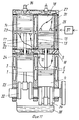
Двигатель содержит левый рабочий цилиндр 1 и правый рабочий цилиндр 2, в которых перемещаются поршни 3 и 4. Каждый поршень связан со своим кривошипом 44. За счет смещения кривошипов поршней 3 и 4 по отношению друг к другу на 180o по углу поворота вала поршни 3 и 4 совершают встречное движение и работают в противофазе друг к другу. Над поршнем 3 образована полость цилиндра 5, а над поршнем 4 - полость цилиндра 6. Цилиндр 2 имеет впускное окно 9 и выпускное окно 10. Цилиндр 1 имеет впускное окно 7 и выпускное окно 8. Цилиндры работают независимо друг от друга и каждый из них имеет свою свечу зажигания или форсунку для впрыска топлива 39 (в разрезе левого цилиндра свеча не показана).The engine contains a
Над цилиндром 2 установлена камера впуска 11, а над цилиндром 1 установлена камера выпуска 12. Камеры 11 и 12 изолированы друг от друга и разделены между собой перегородкой 13. В камере впуска 11 размещены два золотника 18 и 19, а в камере выпуска размещены два золотника 20 и 21. Золотники имеют привод по вращению от вала 15, который с помощью шкива 17 связан по вращению с валом двигателя 43. Передаточное отношение по вращению от вала двигателя к валу привода золотников для двухтактного двигателя, компрессора и насоса устанавливается один к одному, а для четырехтактного двигателя два к одному. Вариант двигателя на фиг. 6 и 7 отличается от варианта двигателя на фиг.1 тем, что в камере впуска и камере выпуска размещены по два золотника. В этом случае в камере впуска и камере выпуска каждый золотник работает на свой цилиндр. An
Для удобства рассмотрения на фиг.6 зафиксирован момент, когда поршень левого цилиндра находится в ВМТ, а на фиг.7 после поворота вала двигателя на 180o поршень левого цилиндра переходит в НМТ. Эти два положения поршней позволяют рассмотреть основные фазы работы двухтактного двигателя.For convenience of consideration, in Fig. 6, the moment is recorded when the piston of the left cylinder is in the upper dead center, and in Fig. 7, after the engine shaft is rotated 180 °, the piston of the left cylinder goes into the BDC. These two positions of the pistons allow us to consider the main phases of the operation of a two-stroke engine.
Принцип работы двигателя по описываемому варианту заключается в следующем. The principle of operation of the engine in the described embodiment is as follows.
При положении поршня 4 в НМТ (фиг.6) видно, что закончился рабочий ход поршня 4 и сгоревший газ из полости 6 через выпускное окно 10, перепускной канал 36, окно 31 и окно 24 поступает в камеру выпуска, а затем через окно 42 в атмосферу. Одновременно или с запаздыванием в зависимости от расположения окон 22 на цилиндрической поверхности золотника 18 и окон 24 на цилиндрической поверхности золотника 20 (см. фиг.3 диаграмму фаз газораспределения) газ от нагнетателя 40 через окно 41, окно 22, окно 27 и окно 9 поступает в полость 6 и выталкивает остатки сгоревших газов, т.е. идет продувка и заполнение цилиндра 2 свежим газом. Затем, когда поршень 4 пошел к ВМТ, при повороте золотников 18 и 20 окна 31 и 27 закрываются. В цилиндре 2 начинается сжатие газа, а в цилиндре 1 после загорания смеси газ расширяется, и поршень 3 начинает свой рабочий ход. После подхода поршня 3 к НМТ (фиг. 7) начинается продувка и заполнение цилиндра 1 так же, как это происходило в цилиндре 2. Т.е. цикл работы цилиндра 1 и 2 чередуется через 180o угла поворота вала.When the position of the
Во всех вариантах выполнения для обеспечения герметичности закрытия впускных и выпускных окон 9, 10, 7 и 8 цилиндров 1 и 2 в конструкции газового тракта от окон до золотников предусмотрена термостойкая упругая поджимная прокладка 34, которая установлена под седлами 32, 30, 28 и 26. В результате эти седла постоянно поджимаются к золотникам 20, 21, 19 и 18 и компенсируют возможный износ седел. In all embodiments, to ensure the tightness of the closing of the inlet and
Предполагается, что кольцевые седла, контактирующие с цилиндрической поверхностью золотников, выполнены из термостойкого антифрикционного материала типа ф4к20, который не требует для своей работы в узлах трения дополнительной смазки. Для уменьшения износа седел и облегчения их работы окна золотников могут быть выполнены не сплошными, а в виде сетки или с перегородками, что легко выполнить при использовании современных технологий изготовления, например с применением лазерной прошивки металла. В вариантах, показанных на фиг.1, 6 и 7, рассмотрен принцип работы двухтактного двигателя, но конструктивно при соответствующем расположении окон 24, 25, 23 и 22 на цилиндрической поверхности золотников по углу поворота вала предлагаемая поршневая машина может работать и как четырехтактный двигатель, компрессор для сжатия и отсоса газа или насос для перекачки жидкости. It is assumed that the annular saddles in contact with the cylindrical surface of the spools are made of heat-resistant antifriction material type f4k20, which does not require additional lubrication for its work in the friction units. To reduce the wear of saddles and facilitate their work, the spool windows can be made not continuous, but in the form of a grid or with partitions, which is easy to accomplish using modern manufacturing technologies, for example, using laser metal flashing. In the variants shown in figures 1, 6 and 7, the principle of the operation of a two-stroke engine is considered, but structurally with the appropriate arrangement of
Преимущество использования золотников заключается в том, что они имеют цилиндрическую форму и при вращении вала не испытывают инерционных нагрузок, контакт окон золотников с окнами седел осуществляется без динамических нагрузок, возможный износ седел компенсируется за счет постоянного поджатия седел к золотникам упругими подкладками, которые стоят под седлами. Работа распределительных устройства происходит абсолютно бесшумно и не требуются какие-либо регулировки зазоров в процессе эксплуатации. В таком исполнении поршневая машина может работать с повышенной скоростью вращения, что позволяет значительно снизить массу поршневой машины при заданных параметрах мощности или производительности. Могут быть повышены экономические параметры поршневой машины, т.к. можно увеличить проходные сечения впускных и выпускных окон, что не вызывает никаких динамических и инерционных нагрузок на механизм газораспределения. В отличие от кулачкового принципа открытия клапанов подъемного действия окна раскрываются сразу на всю проходную площадь. The advantage of using spools is that they have a cylindrical shape and do not experience inertial loads when the shaft rotates, the spool windows contact the seat windows without dynamic loads, the possible wear of the seats is compensated by constantly pressing the seats to the spools with elastic linings that are under the saddles . The operation of the switchgear is completely silent and does not require any adjustment of the gaps during operation. In this design, the piston machine can operate at an increased rotational speed, which can significantly reduce the mass of the piston machine at specified power or performance parameters. The economic parameters of the reciprocating machine may be increased since it is possible to increase the bore sections of the inlet and outlet windows, which does not cause any dynamic and inertial loads on the gas distribution mechanism. In contrast to the cam principle of opening valves for lifting action, the windows open immediately to the entire passage area.
Если сравнивать поршневую машину в варианте компрессора по сравнению с компрессорами, имеющими самодействующие клапаны, испытывающие большие динамические нагрузки, поршневая машина, не имеющая самодействующих клапанов, может иметь скорость вращения на порядок выше, чем существующие компрессоры и по удельной массе на единицу производительности может конкурировать с винтовыми и центробежными клапанами, т.к. значительно экономичнее из-за отсутствия расчетных газовых зазоров и уменьшения утечек газа в обратном направлении, а также имеет меньшую стоимость изготовления. В результате винтовые и центробежные компрессоры по сравнению с предлагаемой конструкцией поршневого компрессора теряют свое основное преимущество - это отсутствие самодействующих клапанов. If we compare a reciprocating piston machine with a compressor compared to compressors with self-acting valves experiencing high dynamic loads, a piston machine without self-acting valves can have an order of magnitude higher rotation speed than existing compressors and can compete with the specific gravity per unit of output screw and centrifugal valves, as much more economical due to the lack of design gas gaps and the reduction of gas leaks in the opposite direction, and also has a lower manufacturing cost. As a result, screw and centrifugal compressors lose their main advantage over the proposed design of a reciprocating compressor - this is the lack of self-acting valves.
В качестве ближайшего аналога по варианту, описанному в пунктах 4-7 для поршневой машины, используемой как двухтактный двигатель внутреннего сгорания (ДДВС), может рассматриваться ДДВС по патенту РФ [1]. As the closest analogue according to the option described in
Недостатки прототипа заключаются в следующем:
- впускные и выпускные окна расположены на стенке цилиндра в его нижней части и периодически перекрываются поршнем при его движении. В результате возможен унос картерного масла через окна. Для уменьшения уноса картерного масла увеличивают длину поршней и цилиндров, а на поршне в его нижней части устанавливают дополнительные поршневые кольца;
- при движении поршня его поршневые кольца перебегают окна. В результате повышается износ поршневых колец и требуется их специальная фиксация на поршне от проворачивания, чтобы замки поршневых колец не совпали с окнами. Прохождение замков поршневых колец через окна может вызвать поломку поршневых колец.The disadvantages of the prototype are as follows:
- inlet and outlet windows are located on the cylinder wall in its lower part and are periodically blocked by the piston during its movement. As a result, the crankcase oil may be carried through windows. To reduce the entrainment of crankcase oil, the length of the pistons and cylinders is increased, and additional piston rings are installed on the piston in its lower part;
- when the piston moves, its piston rings run across the windows. As a result, the wear of the piston rings increases and their special fixing on the piston from turning is required so that the locks of the piston rings do not coincide with the windows. Passing locks of piston rings through windows can cause damage to the piston rings.
Такой двигатель - прототип, так же как и заявляемая конструкция поршневой машины для использования в качестве двухтактного двигателя внутреннего сгорания, содержит рабочий цилиндр с впускными и выпускными окнами. Such an engine is a prototype, as well as the inventive design of a piston machine for use as a two-stroke internal combustion engine, contains a working cylinder with inlet and outlet windows.
Задачей изобретения в части второго варианта дополнительно является также отказ от размещения впускных и выпускных окон в нижней части стенки цилиндра. В результате повышается надежность двигателя и улучшаются его экономические параметры. The objective of the invention in part of the second option is also the refusal to place the inlet and outlet windows in the lower part of the cylinder wall. As a result, engine reliability is improved and its economic parameters are improved.
Сущность поршневой машины по пунктам 4-7 формулы изобретения поясняется на фиг. 8, 9, 10, которые имеют следующий перечень позиций:
Вариант по пунктам 4, 5 и 7
1 - рабочий цилиндр левый;
2 - рабочий цилиндр правый;
3 - поршень цилиндра 1;
4 - поршень цилиндра 2;
5 - полость цилиндра 1;
6 - полость цилиндра 2;
7 - впускное окно цилиндра 2;
8 - выпускное окно цилиндра 1;
9 - канал, сообщающий полости 5 и 6;
10 - свеча зажигания или форсунка;
11 - разделяющая перегородка;
12 - камера впуска;
13 - камера выпуска;
14 - направляющий цилиндр (золотник) камеры 12;
15 - направляющий цилиндр камеры 13;
16 - стакан (золотник) цилиндра 14;
17 - стакан цилиндра 15;
18 - нагнетатель;
19 - впускное окно камеры 12;
20 - выпускное окно камеры 13;
21 - впускное окно направляющего цилиндра 15 камеры выпуска;
22 - выпускное окно направляющего цилиндра 14 камеры впуска;
23 - впускное окно стакана 17;
24 - выпускное окно стакана 16;
25 - перепускной канал из камеры 12 в полость 6;
26 - перепускной канал из полости 5 в камеру 13;
27 - шток, соединяющий поршень и стакан;
28 - коленвал двигателя;
29 - кривошип;
30 - маслозаполненный картер механизма движения.The essence of the piston machine according to claims 4-7 is illustrated in FIG. 8, 9, 10, which have the following list of positions:
1 - left working cylinder;
2 - the working cylinder is right;
3 - the piston of
4 - the piston of the
5 -
6 - the cavity of the
7 - inlet window of
8 - exhaust window of
9 -
10 - a spark plug or nozzle;
11 - dividing wall;
12 - intake chamber;
13 - exhaust chamber;
14 - guide cylinder (spool) of the
15 - guide cylinder of the
16 - a glass (spool) of the
17 - a
18 - supercharger;
19 - inlet window of the
20 - the outlet window of the
21 - inlet window of the
22 - exhaust window of the
23 - the inlet window of the
24 - exhaust window of the
25 - bypass channel from the
26 - bypass channel from the
27 - a rod connecting the piston and the glass;
28 - engine crankshaft;
29 - crank;
30 - oil-filled crankcase movement mechanism.
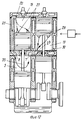
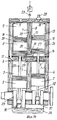
На фиг. 8 изображен двигатель по пунктам формулы 4, 5 и 7, имеющий минимум два смежных взаимосвязанных рабочих цилиндра с общей камерой сгорания, у которых один цилиндр имеет впускные окна, а другой цилиндр имеет выпускные окна. Поршни цилиндров совершают движение в одном направлении, и каждый из них связан со своим кривошипом. При отклонении кривошипов между собой на угол α по направлению вращения вала может быть обеспечено опережение открытия и закрытия выпускных окон по отношению к впускным окнам за счет опережения движения по направлению вращения поршня цилиндра с выпускными окнами. Для продувки и заполнения цилиндров использован внешний источник наддува, например турбонагнетатель. Принцип работы многоцилиндрового двигателя с четным количеством цилиндров не будет отличаться от двигателя, имеющего два смежных взаимосвязанных цилиндра, а поэтому для рассмотрения предложен двухцилиндровый двигатель. In FIG. 8 shows an engine according to
Двигатель, показанный на фиг. 8, имеет два смежных взаимосвязанных цилиндра 1 и 2, в которых перемешаются поршни 3 и 4, связанные с кривошипами 29. Над поршнями 3 и 4 образованы полости 5 и 6 рабочих цилиндров, которые соединены между собой каналом 9. Цилиндр 2 имеет впускные окна 7, а цилиндр 1 имеет выпускные окна 8. Цилиндры 1 и 2 можно рассматривать как один сдвоенный цилиндр, который имеет общую камеру сгорания и одну на два цилиндра свечу зажигания или форсунку для впрыска топлива 10. Над цилиндрами 1 и 2 через разделяющую перегородку 11 установлены камера впуска, которая имеет впускное окно 19, и изолированная от камеры впуска 12 камера выпуска 13, которая имеет выпускное окно 20. К впускному окну 19 камеры впуска 12 подключен нагнетатель 19. Камера впуска имеет выпускное окно 22, которое с помощью перепускного канала 25 соединяется с полостью 6 цилиндра 2, а камера выпуска имеет впускное окно 21, которое с помощью перепускного канала 26 соединяется с полостью 5 цилиндра 1. Внутри камер впуска и выпуска перемещаются заслонки 16 и 17, которые с помощью штоков 27 по перемещению связаны с поршнями цилиндров. Заслонки 16 и 17 служат для перекрытия окон 21 и 22 и выполнены, например, в виде полых золотников круглого или прямоугольного сечения, которые контактируют с направляющими стенками 14 и 15 камеры впуска и выпуска. В верхней части заслонок в осевом направлении выполнены окна 23 и 24, которые при положении поршней в НМТ совпадают с окнами 21 и 22. При движении поршней к ВМТ окна 21 и 22 перекрываются заслонками. Уплотнение между окнами 21 и 22 и поверхностью заслонок 16 и 17 в момент перекрытия окон 21 и 22 достигается, например, за счет специального упругого уплотнения, которое выполнено на направляющих стенках 14 и 15. The engine shown in FIG. 8 has two adjacent
Стадии рабочего цикла двухтактного двигателя зависят от положения поршней по отношению к ВМТ и НМТ. На фиг. 8 показана стадия рабочего цикла, когда поршни 3 и 4 находятся в НМТ. The stages of the working cycle of a two-stroke engine depend on the position of the pistons with respect to TDC and BDC. In FIG. 8 shows the stage of the duty cycle when the
Принцип работы двигателя заключается в следующем. The principle of operation of the engine is as follows.
При положении поршня в НМТ окна 21 и 23, а также окна 22 и 24 совмещены. Это значит, что закончился выпуск сгоревших газов из полостей 5 и 6. Выпуск газа происходит в следующей последовательности. Сначала из полости 6 через канал 9. Затем из полости 5 через окно 8, перепускной канал 26, окна 21 и 23, камеру выпуска и далее через окно 20 в атмосферу. When the piston is in the BDC, the
Одновременно идет последовательная продувка рабочих полостей цилиндра в направлении - газ поступает от нагнетателя 18, через окно 19, окна 24 и 23, перепускной канал 25, окно 7, полость 6 канал 9, полость 5, окно 8, перепускной канал 26, окно 21 и 23, камеру выпуска и далее через окно 20 в атмосферу. At the same time, sequential purging of the working cavities of the cylinder in the direction takes place - gas flows from the
Продувка и заполнение полостей 5 и 6 продолжается и при начале движения поршней к ВМТ, пока не перекроются окна 21 и 22. За счет смещения кривошипов по углу поворота вала можно обеспечить опережение открытия и закрытия выпускного окна 21 по отношению к впускному окну 22. The purging and filling of
Тогда, после закрытия окна 21 заполнение полостей будет продолжаться через еще открытое окно 22, что создаст условия для заполнения рабочих полостей с избыточным давлением, которое может обеспечить нагнетатель 18. После закрытия окон 21 и 22 в результате движения поршней 3 и 4 к ВМТ в полостях 5 и 6 начинается сжатие. При подходе поршней к ВМТ происходит
зажигание смеси от свечи 10 или самовоспламенение смеси после впрыска топлива через форсунку (дизельный вариант). Газ расширяется, начинается рабочий ход поршней, и последние движутся к НМТ. При открытии окна 21 происходит выпуск сгоревших газов, продувка и заполнение полостей 5 и 6 через окно 22, и процесс повторяется каждый газ при повороте вала двигателя на 360o.Then, after closing the
ignition of the mixture from the
Сущность варианта выполнения поршневой машины по пунктам 4, 6 и 7 поясняется на фиг. 9 и 10, которые имеют следующий перечень позиций:
1 - рабочий цилиндр левый;
2 - рабочие цилиндр правый;
3 - поршень цилиндра 1;
4 - поршень цилиндра 2;
5 - полость цилиндра 1;
6 - полость цилиндра 2;
7 - впускное окно цилиндра 2;
8 - выпускное окно цилиндра 2 ;
9 - впускное окно цилиндра 1;
10 - выпускное окно цилиндра 1;
11 - свеча зажигания или форсунка;
12 - разделяющая перегородка;
13 - камера впуска;
14 - камера выпуска;
15 - направляющий цилиндр камеры впуска;
16 - направляющий цилиндр камеры выпуска;
17 - стакан (золотник камеры впуски);
18 - стакан камеры выпуска;
19 - впускное окно камеры впуска;
20 - выпускное окно камеры выпуска;
21 - впускное окно камеры выпуска левое;
22 - впускное окно камеры выпуска правое;
23 - выпускное окно камеры впуска левое;
24 - выпускное окно камеры впуска правое;
25 - окно верхнее стакана 17;
26 - окно нижнее стакана 17;
27 - окно верхнее стакана 18;
28 - окно нижнее стакана 18;
29 - перепускной канал из камеры впуска в полость 6;
З0 - перепускной канал из полости 6 в камеру выпуска;
31 - перепускной канал из камеры впуска в полость 5;
32 - перепускной канал из полости 5 в камеру выпуска;
33 - шток, соединяющий поршень и стакан;
34 - коленвал двигателя;
35 - кривошип левый;
36 - кривошип правый;
37 - маслозаполненный картер механизма движения;
38 - нагнетатель.The essence of the embodiment of the piston machine in
1 - left working cylinder;
2 - working cylinder right;
3 - the piston of
4 - the piston of the
5 -
6 - the cavity of the
7 - inlet window of
8 - exhaust window of the
9 - inlet window of
10 - exhaust window of
11 - a spark plug or nozzle;
12 - dividing wall;
13 - intake chamber;
14 - exhaust chamber;
15 - guide cylinder of the intake chamber;
16 - guide cylinder of the exhaust chamber;
17 - a glass (inlet chamber spool);
18 - a glass of the exhaust chamber;
19 - inlet window of the intake chamber;
20 - exhaust window of the exhaust chamber;
21 - left inlet window of the exhaust chamber;
22 - inlet window of the exhaust chamber, right;
23 - left inlet exhaust chamber window;
24 - outlet window of the intake chamber, right;
25 - the upper window of the
26 - window
27 - the upper window of the
28 - window
29 - bypass channel from the inlet chamber to the
Z0 - bypass channel from the
31 - bypass channel from the inlet chamber to the
32 - bypass channel from the
33 - a rod connecting the piston and the glass;
34 - engine crankshaft;
35 - crank left;
36 - crank right;
37 - oil-filled crankcase of the movement mechanism;
38 - supercharger.
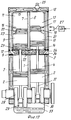
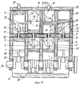
На фиг. 9 и 10 изображен двухтактный двигатель по пунктам 4, 6 и 7, содержащий два смежных независимых рабочих цилиндра, каждый из которых имеет свои впускные и выпускные окна, а их поршни совершают встречное движение и работают в противофазе по отношению друг к другу. Поршни с помощью штоков соединены с заслонками, которые перемещаются в камере впуска и выпуска и перекрывают окна каналов, которые подведены к впускным и выпускным окнам цилиндров, двигатель может быть многоцилиндровым с четным количеством цилиндров, из которых каждые два смежных цилиндра имеют поршни, совершающие встречное движение. In FIG. 9 and 10 depict a two-stroke engine according to
Принцип работы такого многоцилиндрового двигателя не будет отличаться от двигателя, имеющего два смежных цилиндра с поршнями, совершающими встречное движение, а поэтому принцип работы двигателя достаточно рассмотреть на примере двухцилиндрового двигателя. The principle of operation of such a multi-cylinder engine will not be different from an engine having two adjacent cylinders with pistons that counter-move, and therefore it is sufficient to consider the principle of engine operation using an example of a two-cylinder engine.
Двигатель на фиг. 9 и 10 содержит левый рабочий цилиндр 1 и правый рабочий цилиндр 2, в которых перемещаются поршни 3 и 4. Каждый поршень связан со своим кривошипом 35 и 36. За счет смещения кривошипов поршней 3 и 4 по отношению друг к другу на 180o по углу поворота вала поршни 3 и 4 совершает встречное движение и работают в противофазе друг к другу. Над поршнем 3 образована полость цилиндра 5, а над поршнем 4 образована полость цилиндра 6. Цилиндр 2 имеет впускное окно 7 и выпускное окно 8. Цилиндр 1 имеет впускное окно 9 и выпускное окно 10. Цилиндры 1 и 2 работают независимо друг от друга, и каждый из них имеет свою свечу зажигания или форсунку для впрыска топлива 11. Над цилиндрами 1 и 2 через разделяющую перегородку 12 установлены камера впуска 13, которая имеет впускное окно 19, и изолированная от камеры впуска 13 камера выпуска 14, которая имеет выпускное окно 20. К впускному окну 19 камеры впуска 13 подключен нагнетатель 38. Камера впуска имеет выпускное окно 24, которое с помощью перепускного канала 29 соединяется с полостью 6 цилиндра 2, а камера выпуска имеет впускное окно 21, которое с помощью перепускного канала 32 соединяется с полостью 5 цилиндра 1. Внутри камер впуска и выпуска перемещаются заслонки 17 и 18, которые с помощью штоков 33 по перемещению связаны с поршнями цилиндров. Заслонки 17 и 18 служат для перекрытия окон 21 и 24 и выполнены, например, в виде золотников круглого или прямоугольного сечения, которые контактируют с направляющими стенками 15 и 16 камеры впуска и выпуска. В верхней части заслонок в осевом направлении выполнены окна 25 и 27, которые при положении поршней в НМТ совпадают с окнами 21 и 24. При движении поршней к ВМТ окна 21 и 24 перекрываются заслонками. Уплотнение между окнами 21 и 24 и поверхностью заслонок 17 и 18 в момент перекрытия окон 21 и 24 достигается, например, за счет специального упругого поджимного уплотнения, которое выполнено на направляющих стенках 15 и 16.The engine of FIG. 9 and 10 contains a
Стадии рабочего цикла двухтактного двигателя зависят от положения поршней по отношению к ВМТ и НМТ. На фиг. 9 показана стадия рабочего цикла, когда поршень 3 находится в ВМТ, а поршень 4 в НМТ. The stages of the working cycle of a two-stroke engine depend on the position of the pistons with respect to TDC and BDC. In FIG. 9 shows the stage of the duty cycle when the
Принцип работы двигателя заключается в следующем. The principle of operation of the engine is as follows.
При положении поршня 4 в НМТ окна 21 и 27, а также окна 25 и 24 совмещаются. Это значит, что закончился выпуск сгоревших газов из полости 6. Выпуск газа происходит в следующей последовательности. Через окно 8, перепускной канал 30, окно 22 и окно 28 в камеру выпуска 14 и далее через окно 20 в атмосферу. Одновременно идет продувка полости 6 в направлении - газ поступает от нагнетателя 38 через окно 19, окна 25 и 24, перепускной канал 29, окно 7, полость 6, окно 8, перепускной канал 30, окна 22 и 28, камеру выпуска и далее в атмосферу. Продувка и заполнение полости 6 продолжаются и при начале движения поршня 4 к ВМТ, пока не перекроются окна 22 и 24. За счет смещения кривошипов поршней по углу поворота вала можно обеспечить опережение открытия и закрытия окна 22 по отношению к окну 24. Тогда после закрытия окна 21 заполнение полости 6 будет продолжаться через еще открытое окно 24, что создаст условия для заполнения полости 6 с избыточным давлением, которое может обеспечить нагнетатель 38. После закрытия окон 22 и 24 в результате движения поршня 4 к ВМТ в полости 6 начинается сжатие. When the position of the
Пока поршень 4 идет вверх на сжатие, поршень 3 совершает рабочих ход в результате расширения газа после его зажигания в полости 5. While the
При подходе поршня 4 к ВМТ происходит зажигание смеси в полости 6, газ расширяется и начинается рабочий ход поршня 4. В этот момент поршень 3 находится в НМТ и в цилиндре 1 происходит продувка и заполнение полости 5 свежим газом. Таким образом, циклы в цилиндрах 1 и 2 повторяются, и рабочий ход каждого поршня происходит через 360o угла поворота вала, а рабочие ходы поршней в двухцилиндровом двухтактном двигателе, отраженном на фиг. 9 и 10, повторяются через 180o угла поворота вала.When the
ДДВС в таком исполнении будет иметь высокую надежность, т.к. имеет маслозаполненный картер механизма движения и высокую экономичность, т.к. при использовании впрыска топлива непосредственно в цилиндр после закрытая впускных и выпускных окон исключаются потери топлива через окна. Кроме того, исключаются потери и вынос картерного масла через окна цилиндра, т.к. окна находятся в верхней части цилиндра и не перекрываются поршнем, т.е. условия работы по смазке такие же, как в четырехтактном двигателе. The engine in this design will have high reliability, because It has an oil-filled crankcase of the movement mechanism and high efficiency, because when using fuel injection directly into the cylinder after the closed intake and exhaust windows, fuel losses through the windows are eliminated. In addition, the loss and removal of crankcase oil through the cylinder windows are eliminated, as the windows are in the upper part of the cylinder and do not overlap with the piston, i.e. lubrication conditions are the same as in a four-stroke engine.
В качестве ближайшего прототипа для поршневой машины, используемой как двухтактный двигатель внутреннего сгорания и описанной в пункте 8 формулы изобретения, может рассматриваться конструкция двухрядного ДДВС по патенту РФ [1]. As the closest prototype for a piston machine used as a two-stroke internal combustion engine and described in
Недостатком ближайшего прототипа является то, что в вариантах 1, 3, 4 и 5 прототипа впускные и выпускные окна рабочих цилиндров ДДВС находятся в нижних частях цилиндров над поршнем при его положении в нижней мертвой точке (см. фиг. 1, 3, 5, 11, 13, 14, 15, 16, 17, 18, 19, 20, 21, 22 и 23 прототипа). Такое расположение окон влечет за собой необходимость увеличения длины цилиндров и поршнем для перекрытия окон при положении поршней в верхней мертвой точке. В противном случае возникает вероятность выноса масла из картера двигателя в выпускные окна и попадания топлива в картер двигателя через впускные окна, кроме того, по этой же причине необходимо размещать дополнительные поршневые кольца на нижней части юбки поршня. The disadvantage of the closest prototype is that in
Как и прототип, предлагаемый вариант ДДВС содержит рабочие цилиндры, расположенные через разделяющую перегородку один над другим, у которых поршни цилиндров первого ряда связаны штоками с поршнями цилиндров второго ряда, а рабочий цилиндр выполнен сдвоенным и имеет впускные и выпускные окна и общую камеру сгорания, сообщающую его рабочие полости, которые расположены по обе стороны перегородки. Like the prototype, the proposed variant of the internal combustion engine contains working cylinders located one above the other through the separating partition, in which the pistons of the cylinders of the first row are connected by rods to the pistons of the cylinders of the second row, and the working cylinder is doubled and has inlet and outlet windows and a common combustion chamber that communicates its working cavity, which are located on both sides of the septum.
Задачей изобретения в части третьего варианта дополнительно является упрощение конструкции двигателя и снижение его удельной массы на единицу мощности, а также повышение экономичности и уменьшение расхода картерного масла. The objective of the invention in part of the third option is additionally to simplify the design of the engine and reduce its specific gravity per unit of power, as well as increase efficiency and reduce consumption of crankcase oil.
При выполнении по третьему варианту двухрядный ДДВС имеет минимум две смежных спарки поршней, каждая из которых имеет два поршня, связанных штоком. When performing the third embodiment, a two-row engine has at least two adjacent pairs of pistons, each of which has two pistons connected by a rod.
При этом цилиндры первого ряда отделены от цилиндров второго ряда перегородкой. Во втором ряду рабочий цилиндр одной спарки поршней имеет впускные окна, а рабочий цилиндр второго ряда другой спарки поршней имеет выпускные окна. ДДВС может быть многоцилиндровым, но тогда должен иметь четное количество спарок поршней. In this case, the cylinders of the first row are separated from the cylinders of the second row by a partition. In the second row, the working cylinder of one pair of pistons has inlet windows, and the working cylinder of the second row of the other pair of pistons has outlet windows. The engine may be multi-cylinder, but then it must have an even number of piston pairs.
Для лучшего заполнения рабочих цилиндров кривошип поршня цилиндра с выпускным окном может иметь отклонение по углу поворота вала в направлении вращения от кривошипа поршня цилиндра с впускным окном. To better fill the working cylinders, the crank of the piston of the cylinder with the outlet window may have a deviation in the angle of rotation of the shaft in the direction of rotation from the crank of the piston of the cylinder with the inlet window.
В результате обеспечивается опережение открытия и закрытия выпускных окон по отношению к впускным окнам. Каждая спарка поршней связана со своим кривошипом и в зависимости от расположения кривошипов по отношению друг к другу по углу поворота вала может совершать движение в одном или встречном направлении. As a result, the opening and closing of the outlet windows is prevented in relation to the inlet windows. Each pair of pistons is connected with its own crank and, depending on the location of the cranks relative to each other in terms of the angle of rotation of the shaft, can move in one or the opposite direction.
Изложенная сущность поршневой машины по пункту 8 формулы изобретения в вариантах исполнения 1, 2, 3 и 4 поясняется на фиг.11-15, которые имеют следующий перечень позиций:
Исполнение 1, фиг.11 и 12
1 - рабочий цилиндр левый первого ряда;
2 - рабочий цилиндр правый первого ряда;
3 - поршень цилиндра 1;
4 - поршень цилиндра 2;
5 - полость рабочего цилиндра 1;
6 - полость рабочего цилиндра 2;
7 - впускное окно полости 5;
8 - выпускное окно полости 5;
9 - впускное окно полости 6;
10 - выпускное окно полости 6;
11 - разделяющая перегородка;
12 - рабочий цилиндр двухстороннего действия второго ряда левый;
13 - рабочий цилиндр двухстороннего действия второго ряда правый;
14 - поршень цилиндра 12;
15 - поршень цилиндра 13;
16 - полость рабочего цилиндра 12 над поршнем;
17 - полость рабочего цилиндра 12 под поршнем;
18 - полость рабочего цилиндра 13 над поршнем;
19 - полость рабочего цилиндра 13 под поршнем;
20 - впускное окно полости 16;
21 - выпускное окно полости 16;
22 - впускное окно полости 17;
23 - выпускное окно полости 17;
24 - перепускное канал, соединяющий полости 6 и 17;
25 - перепускной канал, соединяющий полости 5 и 16;
26 - впускное окно полости 18;
27 - выпускное окно полости 18;
28 - впускное окно полости 19;
29 - выпускное окно полости 19;
30 - перепускной канал, соединяющий полости 19 и 5;
31 - перепускной канал, соединяющий полости 18 и 6;
32 - коленвал двигателя (механизм движения поршней);
33 - кривошип левый;
34 - кривошип правый;
35 - штоки, соединяющие спарки поршней;
36 - свеча зажигания или форсунка;
37 - нагнетатель;
38 - маслозаполненный картер механизма движения.The stated essence of the piston machine according to
1 - working cylinder left of the first row;
2 - working cylinder, right, first row;
3 - the piston of
4 - the piston of the
5 - the cavity of the working
6 - the cavity of the working
7 - the inlet window of the
8 - the outlet window of the
9 - the inlet window of the
10 - the outlet window of the
11 - dividing wall;
12 - left-hand side working cylinder of the second row of the second row;
13 - the working cylinder of the bilateral action of the second row, right;
14 - the piston of the
15 - the piston of the
16 - the cavity of the working
17 - the cavity of the working
18 - the cavity of the working
19 - the cavity of the working
20 - the inlet window of the
21 - the outlet window of the
22 - the inlet window of the
23 - the outlet window of the
24 - bypass channel connecting the
25 - bypass channel connecting the
26 - the inlet window of the
27 - the outlet window of the
28 - the inlet window of the
29 - the outlet window of the
30 - bypass channel connecting the
31 - bypass channel connecting the
32 - engine crankshaft (piston movement mechanism);
33 - crank left;
34 - crank right;
35 - rods connecting the pairs of pistons;
36 - spark plug or nozzle;
37 - supercharger;
38 - oil-filled crankcase movement mechanism.
На фиг. 11 и 12 изображен двухрядный двигатель в исполнении 1, имеющий минимум две спарки поршней, каждая из которых имеет поршни, связанные между собой штоками и соединена со своим кривошипом. In FIG. 11 and 12 depict a two-row engine in
Кривошипы каждых двух пар поршней имеет отклонения между собой по углу поворота вала на 180o или 180+α° и обеспечивают встречное движение пар поршней и работы их цилиндров в противофазе по отношению друг к другу. При отклонении кривошипов между собой на угол 180+α° обеспечивается опережение открытия и закрытия выпускных окон цилиндра 12 по отношению к впускным окнам цилиндра 13.The cranks of each two pairs of pistons have deviations between themselves in the angle of rotation of the shaft by 180 o or 180 + α ° and provide oncoming movement of the pairs of pistons and the operation of their cylinders in antiphase with respect to each other. When the cranks deviate from each other by an angle of 180 + α ° , the opening and closing of the outlet windows of the
Принцип работы двухрядного многоцилиндрового двигателя с четным количеством пар поршней (больше двух) не будет отличаться от двухрядного двигателя, имеющего две взаимосвязанные пары поршней, а поэтому для рассмотрения предложен двигатель с двумя парами поршней. The principle of operation of a two-row multi-cylinder engine with an even number of piston pairs (more than two) will not differ from a two-row engine having two interconnected pairs of pistons, and therefore, an engine with two pairs of pistons is proposed for consideration.
Принцип работы такого двигателя можно рассматривать по стадиям рабочего цикла в зависимости от положения поршней по отношению к нижней мертвой точке (НМТ) и к верхней мертвой точке (ВМТ) в интервале от 0o до 360o угла поворота вала, т.к. в этом интервале совершается полный pa6oчий цикл двухтактного двигателя в два такта, чередующихся через 180o.The principle of operation of such an engine can be considered according to the stages of the working cycle depending on the position of the pistons with respect to the bottom dead center (BDC) and top dead center (TDC) in the range from 0 o to 360 o the angle of rotation of the shaft, because in this interval, a complete six-hour cycle of the two-stroke engine in two cycles is performed, alternating through 180 o .
На фиг.11 и 12 показан вариант исполнения 1, когда все цилиндры являются рабочими, а продувка всех полостей цилиндров осуществляется от постороннего источника, например от нагнетателя. 11 and 12 show an
На фиг. 11 показана стадия рабочего цикла, когда поршни 3 и 14 левой спарки поршней подходят к BМT, а поршни 15 и 4 правой пары поршней подходят к НМТ. Ha фиг.12 показана стадия рабочего цикла, когда поршни левой и правой спарки поршней меняются местами после поворота вала двигателя на 180o.In FIG. 11 shows the stage of the working cycle, when the
У двигателя на фиг.11 и 12 в первом ряду находятся цилиндры 1 и 2 одностороннего действия, а во втором ряду находятся цилиндры 12 и 13 двухстороннего действия. Над поршнями 3 и 4 первого ряда цилиндров, а также над и под поршнями 14 и 15 второго ряда цилиндров образованы полости рабочих цилиндров, которые имеют впускные и выпускные окна. The engine in FIGS. 11 and 12 in the first row has single-acting
Для продувки и наддува всех полостей рабочих цилиндров используется нагнетатель 37. Рабочий цилиндр полости 18 (фиг.11) имеет впускные окна 26 и выпускные окна 27. Рабочий цилиндр 2 полости 6 имеет впускные окна 9 и выпускные окна 10. Рабочий цилиндр полости 17 имеет впускные окна 22 и выпускные окна 23. Полости 18 и 6 рабочих цилиндров соединены между собой перепускным каналом 31, а полости 6 и 17 соединены перепускным каналом 24. В результате 3 полости 18, 6 и 17 сообщаются между собой и имеют общую камеру сгорания, а рабочие цилиндры этих полостей являются строенными. При этом полость 6 рабочего цилиндра 2 первого ряда оказывается проточной и расположена между полостями 18 и 17, которые от полости 6 находятся во втором ряду по другую сторону перегородки 11. A
Рабочий цилиндр 13 полости 19 (фиг.12) имеет впускные окна 28 и выпускные окна 29. Рабочий цилиндр 1 полости 5 имеет впускные окна 7 и выпускные окна 8. Рабочий цилиндр 12 полости 16 имеет впускные окна 20 и выпускные окна 21. Полости 19 и 5 соединены между собой перепускным каналом 30, а полости 5 и 16 соединены между собой перепускным каналом 25. В результате три полости 19, 5 и 16 сообщаются между собой и имеют общую камеру сгорания, а рабочие цилиндры этих полостей являются строенными. При этом полость 5 рабочего цилиндра 1 первого ряда, так же как и полость 6, оказывается проточной, т.к. расположена между полостями 19 и 16, которые от полости 5 находится по другую сторону перегородки. Строенные рабочие цилиндры оснащены свечами зажигания или форсунками для впрыска топлива 36. The working
Отличительной особенностью ДДВС по п. 8 формулы изобретения в исполнении 1 по сравнению с ближайшим прототипом (1) является то, что участвующие в работе рабочие цилиндры являются не сдвоенными, а строенными. При этом полости рабочих цилиндров первого ряда являются проточными, а их впускные и выпускные окна находятся в верхней части цилиндров и не перекрываются поршнем. Такое расположение окон у цилиндров первого ряда позволяет отказаться от увеличения длины поршней и цилиндров, а также исключает вынос масла из картера двигателя, что имеет место при расположение окон над поршнем при его положении в НМТ, как у прототипа. В результате упрощается конструкция ДДВС, повышается его надежность и снижается удельная масса, отнесенная на единицу мощности, а также повышается экологическая частота выхлопных газов и уменьшается расход картерного масла. A distinctive feature of the engine according to
Принцип работы ДДВС в данном исполнении заключается в следующем. The principle of operation of the engine in this design is as follows.
На фиг. 11 зафиксирован момент, когда в строенном рабочем цилиндре, содержащем соединенные между собой полости 18, 6 и 17, заканчивается рабочий ход поршней 15, 4 и 14 и последние подошли к НМТ. Соответственно заканчивается выпуск cгopeвшиx газов через окна 23. In FIG. 11, the moment is recorded when the working stroke of the
Одновременно идет последовательная продувка полостей 18, 6 и 17 свежим газом от нагнетателя 37. В начале газ поступает от нагнетателя 37 к впускным окнам 26, заполняет полость 18 и через перепускной канал 31 поступает в полость 6 и затем через перепускной канал 24 поступает в полость 17. К моменту окончания продувки полостей 18, 6 и 17 выпускные окна 23 закрываются, а впускные окна 26 еще открыты. At the same time, sequential purging of the
В результате в полостях 18, 6 и 17 создается избыточное давление, которое может создать нагнетатель 37. В это же время происходит зажигание топливной смеси над поршнями 3 и 14 и под поршнем 15. Газ расширяется и происходит рабочий ход поршней в строенном цилиндре, имеющем соединенные между собой полости 5, 16 и 19. В результате поршни 3 и 14 левой спарки совершают рабочий ход и движутся вниз к НМТ, а поршень 15 правой спарки совершает рабочий ход и движется вверх к ВМТ. As a result, an excess pressure is created in the
Сначала открываются окна 21 (см. фиг.12) и происходит выпуск сгоревших газов. Затем начинают открываться впускные окна 28 и происходит продувка полостей 19, 5 и 16. После закрытия окон 21 окна 28 еще открыты в полостях 19, 5 и 16 и давление растет выше атмосферного до величины избыточного давления, создаваемого нагнетателем 37. First,
Далее опять происходит загорание топливной смеси уже под поршнем 14 и над поршнями 15 и 4. Левая спарка поршней идет вверх к ВМТ, а правая спарка поршней идет вниз к НМТ, и процесс повторяется. Такой двухрядный ДДВС будет иметь удельную массу на единицу мощности, в четыре и более раз меньшую, чем однорядный четырехтактный двигатель такой же мощности. Then again, the fuel mixture ignites already under the
Исполнение 2, фиг.13
1 - сдвоенный рабочий цилиндр одностороннего действия первого ряда;
2 - поршни цилиндра 1;
3 - полость цилиндра 1 левая;
4 - полость цилиндра 1 правая;
5 - впускное окно цилиндра 1;
6 - выпускное окно цилиндра 1;
7 - цилиндр двухстороннего действия второго ряда левый;
8 - цилиндр двухстороннего действия второго ряда правый;
9 - поршень цилиндра 7;
10 - поршень цилиндра 8;
11 - полость рабочего цилиндра 7 над поршнем 9;
12 - полость рабочего цилиндра 7 под поршнем 9;
13 - полость рабочего цилиндра 8 над поршнем 10;
14 - полость рабочего цилиндра 8 под поршнем 10;
15 - впускное окно полости 11;
16 - выпускное окно полости 11;
17 - впускное окно полости 13;
18 - выпускное окно полости 13;
19 - впускное окно полости 14;
20 - выпускное окно полости 12;
21 - перепускной канал, соединяющий полость 13 с полостью 4;
22 - канал, соединяющий полость 4 полостью 3;
23 - перепускной канал, соединяющий полость 3 с полостью 11;
24 - канал, соединяющий полости 14 и 12;
25 - свеча зажигания или форсунка;
26 - нагнетатель;
27 - канал подвода газа от нагнетателя к полостям 13 и 14;
28 - коленвал двигателя (механизм движения поршней);
29 - кривошип левый;
30 - кривошип правый;
31 - шатуны;
32 - штоки, соединяющие спарки поршней;
33 - маслозаполненный картер механизма движения;
34 - разделяющая перегородка.
1 - a double working cylinder of unilateral action of the first row;
2 - pistons of
3 -
4 - the cavity of the
5 - inlet window of
6 - exhaust window of
7 - left-sided cylinder of the second row;
8 - double-acting cylinder of the second row, right;
9 - the piston of the
10 - the piston of the
11 - the cavity of the working
12 - the cavity of the working
13 - the cavity of the working
14 - the cavity of the working
15 - the inlet window of the
16 - the outlet window of the
17 - the inlet window of the
18 - the outlet window of the
19 - the inlet window of the
20 - the outlet window of the
21 - a bypass channel connecting the
22 - channel connecting the
23 - bypass channel connecting the
24 - channel connecting the
25 - spark plug or nozzle;
26 - supercharger;
27 - channel for supplying gas from the supercharger to the
28 - engine crankshaft (piston movement mechanism);
29 - crank left;
30 - crank right;
31 - connecting rods;
32 - rods connecting the pairs of pistons;
33 - oil-filled crankcase of the movement mechanism;
34 is a dividing wall.
На фиг. 13 изображен двухрядный двигатель по пункту 8 формулы изобретения в исполнении 2, имеющий движущиеся в одном направлении минимум две смежные взаимосвязанные пары поршней, каждая из которых имеет два поршня, связанных между собой штоком, и соединена со своим кривошипом. Кривошипы каждых двух смежных пар поршней имеют отклонение между собой по углу поворота вала и обеспечивают опережение открытия и закрытия выпускных окон цилиндра 7 по отношению к впускным окнам цилиндра 8. In FIG. 13 shows a two-row engine according to
Принцип работы двухрядного многоцилиндрового двигателя с четным количеством смежных пар поршней (больше двух) не будет отличаться от двухрядного двигателя, имеющего две взаимосвязанные смежные пары поршней, а поэтому для рассмотрения предложен двигатель с двумя парами поршней. The principle of operation of a two-row multi-cylinder engine with an even number of adjacent pairs of pistons (more than two) will not differ from a two-row engine having two interconnected adjacent pairs of pistons, and therefore, an engine with two pairs of pistons is proposed for consideration.
На фиг.13 показан вариант исполнения 2, когда все цилиндры являются рабочими, их поршни движутся в одном направлении, а продувка всех полостей цилиндров осуществляется от постороннего источника, например нагнетателя. On Fig shows a variant of
У двигателя на фиг.13 в первом ряду находится сдвоенный цилиндр 1 одностороннего действия, состоящий из двух цилиндров 1 и двух поршней 2. In the engine of FIG. 13, in the first row is a double-acting
Над левым поршнем 2 образована полость 3, а над правым поршнем 2 образована полость 4. Полости 3 и 4 соединены между собой каналом 22. Соединенные между собой цилиндры 1 имеют общую камеру сгорания и могут рассматриваться как один сдвоенный цилиндр. Сдвоенный цилиндр 1 имеет впускное окно 5 и выпускное окно 6. Над цилиндром 1 через разделяющую перегородку 34 установлены цилиндры двухстороннего действия 7 и 8, имеющие соответственно поршни 9 и 10. Поршни 9 и 10 второго ряда связаны штоками 32 с поршнями 2 первого ряда. Над поршнями 9 и 10 образованы полости 11 и 13. Под поршнями 9 и 10 образованы полости 12 и 14. Все цилиндры 1, 7 и 8 и все полости 3, 4, 11 и 13 являются рабочими. Для продувки и наддува всех полостей рабочих цилиндров используется нагнетатель 26. Рабочий цилиндр полости 13 имеет впускные окна 17 и выпускные окна 18. Рабочий цилиндр полости 11 имеет впускные окна 15 и выпускные окна 16. Полости 12 и 14 соединены каналом 24 и образуют сдвоенный цилиндр. Этот сдвоенный цилиндр имеет впускные окна 19 и выпускные окна 20. Полость 4 соединена с полостью 13 перепускным каналом 21, а полость 3 соединена с полостью 11 перепускным каналом 23. A
В результате полости 13, 4, 3 и 11 сообщаются между собой и имеют общую камеру сгорания, а рабочие цилиндры этих полостей образуют суммарный цилиндр, состоящий из 4-х цилиндров. При этом полости 4 и 3 являются проточными и расположены между полостями 13 и 11, которые находятся во втором ряду по другую сторону перегородки 34. As a result, the
Сдвоенный цилиндр, состоящий из 2-х полостей 12 и 14 и суммарный цилиндр, состоящий из 4-х полостей 13, 4, 3 и 11 имеют каждый свою свечу зажигания или форсунку для впрыска топлива 25. A twin cylinder, consisting of 2
Отличительной особенностью ДДВС по п. 8 формулы изобретения исполнения 2 по сравнению с ближайшим прототипом (I), также как и по исполнению 1, является то, что часть рабочих цилиндров является не сдвоенной, а суммарный цилиндр имеет количество цилиндров больше 2-х. В рассмотренном случае по исполнению 2 суммарный цилиндр состоит из 4-х цилиндров. A distinctive feature of the engine according to
При этом полости 3 и 4 рабочего сдвоенного цилиндра первого ряда являются проточными, а у сдвоенного цилиндра первого ряда впускные окна 5 и выпускные окна 6 находятся в верхней части цилиндров и не перекрываются поршнем. Такое расположение окон у цилиндров первого ряда в отличие от прототипа дает преимущества, отмеченные ранее. In this case, the
Принцип работы ДДВС в исполнении 2 заключается в следующем. The principle of operation of the engine in
На фиг. 13 зафиксирован момент, когда обе взаимосвязанные пары поршней подходят к НМТ, и заканчивается рабочий процесс в полостях 11, 3, 4 и 13, т. к. происходит выпуск сгоревших газов из этих полостей через выпускные окна 16, которые открылись раньше, чем впускные окна 17. In FIG. 13, the moment is recorded when both interconnected pairs of pistons approach the BDC, and the working process ends in
Затем начинается закрытие выпускных окон 16 и открытие впускных окон 17. В этот момент идет последовательная продувка полостей 13, 4, 3 и 11. После закрытия выпускных окон 16 впускные окна 17 остаются еще открытыми, и начинается заполнение полостей 13, 4, 3 и 11 газом с избыточным давлением, которое может создать нагнетатель. В результате весовое заполнение полостей цилиндров может происходить с коэффициентом наполнения больше единицы. Одновременно заканчивается сжатие газа в полостях 12 и 14, расположенных под поршнями 9 и 10. При подходе поршней к НМТ происходит загорание смеси, газ расширяется и начинается рабочий ход поршней вверх к ВМТ, а следовательно, начинается процесс сжатия газа в полостях 13, 4, 3 и 11. При подходе поршней к ВМТ сначала открываются выпускные окна 20 и идет выпуск сгоревших газов из полостей 12 и 14. Then, the closing of the
При начале закрытия окон 20 и начале открытия окон 19 идет продувка полостей 12 и 14. После закрытия окон 20 начинается заполнение полостей 12 и 14 при открытых окнах 19 с избыточным давлением, равным давлению, которое создает нагнетатель. При подходе поршней к ВМТ происходит загорание смеси в полостях 13, 4, 3 и 11, начинается рабочий ход поршней вниз к НМТ, и процесс повторяется. Т.е. на один оборот вала двигателя приходится два рабочих хода поршней с интервалом через 180o угла поворота вала.At the beginning of the closing of the
Исполнение 3, фиг.14
1 - сдвоенный рабочий цилиндр одностороннего действия первого ряда;
2 - поршни цилиндра 1;
3 - полость цилиндра 1 левая;
4 - полость цилиндра 1 правая;
5 - впускное окно цилиндра 1;
6 - выпускное окно цилиндра 1;
7 - цилиндр двухстороннего действия второго ряда левый;
8 - цилиндр двухстороннего действия второго ряда правый;
9 - поршень цилиндра 7;
10 - поршень цилиндра 8;
11 - полость рабочего цилиндра 7 над поршнем;
12 - полость насосного цилиндра 7 под поршнем;
13 - полость рабочего цилиндра 8 над поршнем;
14 - полость насосного цилиндра 8 под поршнем;
15 - впускное окно полости 11;
16 - выпускное окно полости 11;
17 - впускное окно полости 13;
18 - выпускное окно полости 13;
19 - впускное и выпускное окна полостей 12 и 14;
20 - канал подвода и отвода газа от полостей 12 и 14;
21 - нагнетатель;
22 - канал подвода газа от нагнетателя 21 к полости 13 рабочего цилиндра и к насосным полостям 12 и 14 насосного сдвоенного цилиндра;
23 - обратный клапан;
24 - перепускной канал, соединяющий полость 13 с полостью 4;
25 - канал, соединяющий полость 4 с полостью 3;
26 - перепускной канал, соединяющий полость 3 с полостью 11;
27 - канал, соединяющий полости 12 и 14;
28 - свеча зажигания или форсунка;
29 - коленвал двигателя (механизм движения поршней);
30 - кривошип левый;
31 - кривошип правый;
32 - шатуны;
33 - штоки, соединяющие спарки поршней;
34 - маслозаполненный картер механизма движения.
1 - a double working cylinder of unilateral action of the first row;
2 - pistons of
3 -
4 - the cavity of the
5 - inlet window of
6 - exhaust window of
7 - left-sided cylinder of the second row;
8 - double-acting cylinder of the second row, right;
9 - the piston of the
10 - the piston of the
11 - the cavity of the working
12 - the cavity of the
13 - the cavity of the working
14 - the cavity of the
15 - the inlet window of the
16 - the outlet window of the
17 - the inlet window of the
18 - the outlet window of the
19 - inlet and outlet windows of the
20 - channel for supplying and discharging gas from
21 - supercharger;
22 - channel for supplying gas from the
23 - check valve;
24 - a bypass channel connecting the
25 - channel connecting the
26 - bypass channel connecting the
27 - channel connecting the
28 - spark plug or nozzle;
29 - engine crankshaft (piston movement mechanism);
30 - crank left;
31 - crank right;
32 - connecting rods;
33 - rods connecting the piston pairs;
34 - oil filled crankcase movement mechanism.
На фиг. 14 изображен двухрядный ДДВС по пункту 8 формулы изобретения в исполнении 3, в котором четыре полости, в том числе две над поршнями первого ряда и две над поршнями второго ряда, соединены между собой и являются рабочими. Принцип их работы такой же, как у двигателя в исполнении 2 на фиг. 13. Отличие от исполнения 2 заключается в том, что полости 12 и 14 сдвоенного цилиндра являются насосными и подают газ по перепускному каналу 20 через впускное окно 17 в рабочие цилиндры. При таком исполнении ДДВС может иметь два режима работы - пусковой режим с пониженной мощностью при неработающем нагнетателе 21 и рабочий режим с полной мощностью после включения в работу нагнетателя. В этом случае полная мощность двигателя будет меньше, чем у двигателя в исполнении 2, т.к. вместо шести рабочих полостей в работе будут участвовать только четыре рабочие полости, а две полости из шести работают только как насосные. На фиг.14 рассматривается двигатель, имеющий только 2 спарки поршней. С этим же принципом работы может быть и многоцилиндровый двигатель, имеющий четное количество пар поршней, соединенных штоком. In FIG. 14 shows a two-row engine according to
На фиг. 14 зафиксирован момент, когда обе взаимосвязанные пары поршней подходят к НМТ, и заканчивается рабочий процесс в полостях 3, 4, 11 и 13, расположенных над поршнями. В таком положении поршней из этих полостей через окно 16 происходит выпуск сгоревших газов, а в насосных полостях 12 и 14 заканчивается процесс сжатия газа, т.к. обратный клапан 23 закрыт. При открытии окна 17 сначала начинается процесс продувки рабочих цилиндров, а затем после закрытия окна 16 происходит заполнение рабочих полостей свежим газом. После закрытия окна 17 и начала движения поршней вверх к ВМТ происходит сжатие газа в полостях 3, 4, 11 и 13 и одновременно при открытом обратном клапане 23 начинается заполнение насосных полостей 12 и 14. При подходе поршней к ВМТ происходит загорание топливной смеси, газ расширяется и начинается рабочий ход поршней. In FIG. 14, the moment is recorded when both interconnected pairs of pistons approach the BDC, and the work process ends in
При движении поршней вниз закрывается обратный клапан 23 и газ сжимается в насосных полостях 12 и 14. Рабочий ход поршней заканчивается, когда открывается окно 16 и происходит выпуск сгоревших газов. После открытия окна 17 сжатый газ из насосных полостей 12 и 14 расширяется и по перепускному каналу 20 и окно 17 поступает в рабочие полости. When the pistons move down, the
После падения давления в перепускном канале 20 открывается обратный клапан 26 и дополнительно по каналу 22 газ через окно 17 начинает поступать от нагнетателя 21, который обеспечивает заполнение полостей 13, 4, 3 и 11 с избыточным давлением. При неработающем нагнетателе 21 (пусковой режим работы двигателя) газ в рабочие полости поступает только из насосных полостей 12 и 14. After the pressure drop in the
При работающем нагнетателе 21 обратный клапан 23 открыт и заполнение полостей 12 и 14 может вестись с избыточным давлением. В этом случае двигатель будет развивать полную мощность. При неработающем нагнетателе 21 заполнение полостей 12 и 14 будет происходить газом без избыточного давления и соответственно двигатель будет работать на режиме пониженной мощности. При наличии насосных полостей облегчается запуск двигателя при неработающем нагнетателе, который может работать от энергии выхлопных газов как турбонагнетатель и вступает в работу только после запуска двигателя при достижении расчетного числа оборотов. Наличие насосных полостей позволяет работать двигателю вообще без нагнетателя. When the
Изложенная сущность изобретения по пункту 8 формулы изобретения в исполнении 4 поясняется на фиг. 15, которая имеет следующие позиции:
1 - рабочий цилиндр левый первого ряда;
2 - насосный цилиндр правый первого ряда;
3 - поршень цилиндра 1;
4 - поршень цилиндра 2;
5 - полость рабочего цилиндра 1;
6 - полость насосного цилиндра 2;
7 - впускное окно полости 5;
8 - выпускное окно полости 5;
9 - впускное окно полости 6;
10 - выпускное окно полости 6;
11 - разделяющая перегородка;
12 - цилиндр двухстороннего действия второго ряда левый;
13 - цилиндр двухстороннего действия второго ряда правый;
14 - поршень цилиндра 12;
15 - поршень цилиндра 13;
16 - полость рабочего цилиндра 12 над поршнем;
17 - полость насосного цилиндра 12 под поршнем;
18 - полость насосного цилиндра 13 над поршнем;
19 - полость рабочего цилиндра 13 под поршнем;
20 - впускное окно полости 16;
21 - выпускное окно полости 16;
22 - впускное окно полости 17;
23 - выпускное окно полости 17;
24 - впускное окно полости 18;
25 - выпускное окно полости 18;
26 - впускное окно полости 19;
27 - выпускное окно полости 19;
28 - канал, соединяющий полости 6 и 17;
29 - перепускной канал, соединяющий полости 5 и 16;
30 - перепускной канал, соединяющий полости 5 и 19;
31 - перепускной канал, соединяющий полости 17 и 19;
32 - перепускной канал, соединяющий полости 18 и 19;
33 - перепускной канал, соединяющий полости 6 и 19;
34 - коленчатый вал двигателя (механизм движения поршней);
35 - кривошип левый;
36 - кривошип правый;
37 - шток, соединяющий левую спарку поршней;
38 - шток, соединяющий правую спарку поршней;
39 - свеча зажигания или форсунка;
40 - шатуны;
41 - маслозаполненный картер механизма движения поршней.The foregoing summary of
1 - working cylinder left of the first row;
2 - pump cylinder right of the first row;
3 - the piston of
4 - the piston of the
5 - the cavity of the working
6 - cavity of the
7 - the inlet window of the
8 - the outlet window of the
9 - the inlet window of the
10 - the outlet window of the
11 - dividing wall;
12 - a cylinder of double-acting second row left;
13 - double-acting cylinder of the second row, right;
14 - the piston of the
15 - the piston of the
16 - the cavity of the working
17 - the cavity of the
18 - the cavity of the
19 - the cavity of the working
20 - the inlet window of the
21 - the outlet window of the
22 - the inlet window of the
23 - the outlet window of the
24 - the inlet window of the
25 - the outlet window of the
26 - the inlet window of the
27 - the outlet window of the
28 - channel connecting the
29 - bypass channel connecting the
30 - bypass channel connecting the
31 - bypass channel connecting the
32 - bypass channel connecting the
33 - bypass channel connecting the
34 - engine crankshaft (piston movement mechanism);
35 - crank left;
36 - crank right;
37 - rod connecting the left pair of pistons;
38 - rod connecting the right pair of pistons;
39 - spark plug or nozzle;
40 - connecting rods;
41 - oil-filled crankcase of the mechanism of movement of the pistons.
На фиг. 15 изображен двухрядный ДДВС в исполнении 4, содержащий четное количество связанных штоком поршней, у которого половина цилиндров является рабочими, а другая половина цилиндров является насосными. Для удобства рассмотрения на фиг. 15 показан двухрядный двигатель, имеющий четыре пары связанных штоком поршней, из которых каждые две пары поршней работают самостоятельно и обеспечивают заданный двухтактный цикл работы. Двигатель может быть многоцилиндровым с четным количеством пар поршней. Наличие у двигателя четырех пар поршней позволяет рассмотреть полный двухтактный цикл работы двух пар поршней в диапазоне от 0o до 360o угла поворота вала, т.к. через каждые 180o меняется положение поршней по отношению к ВМТ и НМТ и можно видеть у одной пары поршней начало рабочего хода, а у другой пары поршней начало цикла сжатия.In FIG. 15 shows a two-row engine in
На фиг. 15 показана стадия рабочего цикла, когда поршни 3 и 14 левой спарки поршней подходят к ВМТ, а поршни 4 и 15 правой пары поршней подходят к HМT. Через 180o угла поворота вала поршни левой и правой спарки поршней поменяются местами. Т.к. две пары поршней в левой части двигателя такие же, как две пары поршней в правой части двигателя, обозначение позиции их составляющих элементов будет одинаковым.In FIG. 15 shows the stage of the working cycle when the
У двигателя на фиг. 15 в первом ряду находятся цилиндры 1 и 2 одностороннего действия, а во втором ряду цилиндры 12 и 13 являются цилиндрами двухстороннего действия. Над поршнем 3 первого ряда и над поршнем 14 второго ряда, а также под поршнем 15 второго ряда образованы полости 5, 16 и 19 рабочих цилиндров, которые имеют впускные и выпускные окна, соединены между собой, имеют общую камеру сгорания, общую свечу зажигания или форсунку для впрыска топлива и срабатывают одновременно. In the engine of FIG. 15 in the first row are single-acting
Над поршнем 15 второго ряда и над поршнем 4 первого ряда, а также под поршнем 14 второго ряда образованы полости 18, 6 и 17 насосных цилиндров. Over the
Рабочий цилиндр полости 19 имеет впускные окна 26 и выпускные окна 27. Рабочий цилиндр полости 5 имеет впускные окна 7 и выпускные окна 8. Рабочий цилиндр полости 16 имеет впускные 20 и выпускные окна 21. Насосный цилиндр полости 18 имеет впускные окна 24 и выпускные окна 25. Насосный цилиндр полости 17 имеет впускные окна 22 и выпускные окна 23. Насосный цилиндр полости 6 имеет впускные окна 9 и выпускные окна 10. Насосный цилиндр полости 17 соединен с рабочим цилиндром полости 19 перепускным каналом 31. Насосный цилиндр полости 18 соединен с рабочим цилиндром полости 19 перепускным каналом 32. Рабочий цилиндр полости 19 соединен с рабочим цилиндром полости 5 перепускным каналом 30, а рабочий цилиндр полости 5 соединен с рабочим цилиндром полости 16 перепускным каналом 29. При этом полость 5 рабочего цилиндра первого ряда оказывается проточной и расположена между полостями 19 и 16, которые от полости 5 находятся по другую сторону перегородки 11. В результате рабочие цилиндры полостей 5, 16 и 19 являются строенными. Строенные рабочие цилиндры имеют общую камеру сгорания, общую свечу зажигания или форсунку для впрыска топлива 39. The working cylinder of the
Отличительной особенностью ДДВС в варианте исполнения 4 по сравнению с ближайшим прототипом (1) является то, что участвующие в работе одновременно рабочие цилиндры являются не сдвоенными, как у прототипа, а строенными. При этом полости рабочих цилиндров первого ряда являются проточными, а их впускные и выпускные окна находятся в верхней части цилиндров и не перекрываются поршнем. Также проточными являются полости насосных цилиндров первого ряда, а их впускные и выпускные окна тоже находятся в верхней части цилиндров. A distinctive feature of the internal combustion engine in
Расположение впускных и выпускных окон полостей рабочих и насосных цилиндров в верхней части цилиндра дает преимущества, отмеченные в варианте исполнения 1, 2 и 3. В отличие от варианта исполнения 1 в варианте исполнения 4 для продувки рабочих цилиндров используется не внешний источник продувки, например в виде нагнетателя, а насосные цилиндры. The location of the inlet and outlet windows of the cavities of the working and pump cylinders in the upper part of the cylinder gives the advantages noted in
Принцип работы ДДВС в варианте исполнения 4 заключается в следующем. The principle of operation of the engine in
На фиг. 15 зафиксирован момент, когда в правой половине двигателя в строенном рабочем цилиндре, содержащем соединенные между собой полости 19, 5 и 16, заканчивается рабочий ход поршней 15, 3 и 14. Соответственно заканчивается выпуск сгоревших газов через окна 21. Одновременно или с запаздыванием открываются впускные окна 26, и из насосных полостей 6, 17 и 18 газ поступает сначала в полость 19, затем в полость 5 и далее в полость 16. Т.е. происходит последовательная прямоточная продувка полостей 19, 5 и 16. In FIG. 15, the moment is recorded when the working stroke of the
Если кривошипы двух взаимодействующих смежных спарок имеют отклонение между собой по углу поворота вала на 180+α°, происходит опережение открытия и закрытия выпускных окон 21 по сравнению с впускными окнами 26.If the cranks of two interacting adjacent pairs have a deviation between themselves in the angle of rotation of the shaft by 180 + α ° , the opening and closing of the
Это позволяет улучшить коэффициент наполнения рабочего строенного цилиндра. Возможен вариант, когда для наполнения насосных цилиндров будет использован нагнетатель, создающий давление выше атмосферного. В этом случае в рабочем цилиндре после закрытия выпускных окон 21 давление также может быть поднято выше атмосферного. В это же время в левой половине двигателя (две спарки поршней слева) происходит зажигание топливной смеси над поршнями 14 и 3 и под поршнем 15. Газ расширяется и происходит рабочий ход поршней в строенном цилиндре, имеющем соединенные между собой полости 19, 5 и 16. В результате поршни 14 и 3 движутся к НМТ, а поршень 15 движется к ВМТ. Сначала открываются окна 21, и происходит выпуск сгоревших газов. Затем начинают открываться окна 26, и происходит продувка полостей 19, 5 и 16, а затем их заполнение. К этому времени поршни 14, и 3 в правой половине двигателя (две спарки поршней правые) подошли к ВМТ, а поршень 15 подошел к НМТ. Происходит загорание, и идет рабочий ход поршней в правой половине двигателя. Затем рабочий цикл повторяется. В результате в рассмотренном двигателе за один оборот вала происходит два срабатывания строенных рабочих цилиндров с интервалом через 180o.This allows you to improve the fill factor of the working cylinder. A variant is possible when a supercharger will be used to fill the pump cylinders, creating a pressure above atmospheric. In this case, in the working cylinder after closing the
Источники информации
1. Двухтактный двигатель внутреннего сгорания (варианты). Патент РФ 2143077, МПК F 02 В 33/22, опубл.1999, Бюл. 35.Sources of information
1. Two-stroke internal combustion engine (options). RF patent 2143077, IPC F 02
2. А.К. Михайлов, В.П. Ворошилов. Компрессорные машины: Учебник для вузов - М.: Энергоиздат, 1989, с.11, рис. 1, 2, 6 и 7). 2. A.K. Mikhailov, V.P. Voroshilov. Compressor machines: Textbook for high schools - M .: Energoizdat, 1989, p. 11, Fig. 1, 2, 6 and 7).
Claims (8)
Priority Applications (1)
| Application Number | Priority Date | Filing Date | Title |
|---|---|---|---|
| RU2000115856/06A RU2215879C2 (en) | 2000-06-16 | 2000-06-16 | Piston machine (versions) |
Applications Claiming Priority (1)
| Application Number | Priority Date | Filing Date | Title |
|---|---|---|---|
| RU2000115856/06A RU2215879C2 (en) | 2000-06-16 | 2000-06-16 | Piston machine (versions) |
Publications (2)
| Publication Number | Publication Date |
|---|---|
| RU2000115856A RU2000115856A (en) | 2002-11-20 |
| RU2215879C2 true RU2215879C2 (en) | 2003-11-10 |
Family
ID=32026400
Family Applications (1)
| Application Number | Title | Priority Date | Filing Date |
|---|---|---|---|
| RU2000115856/06A RU2215879C2 (en) | 2000-06-16 | 2000-06-16 | Piston machine (versions) |
Country Status (1)
| Country | Link |
|---|---|
| RU (1) | RU2215879C2 (en) |
Cited By (1)
| Publication number | Priority date | Publication date | Assignee | Title |
|---|---|---|---|---|
| RU2620599C2 (en) * | 2012-01-10 | 2017-05-29 | Пежо Ситроен Отомобиль Са | Control method of forced ignition advance in internal combustion engine |
-
2000
- 2000-06-16 RU RU2000115856/06A patent/RU2215879C2/en not_active IP Right Cessation
Cited By (1)
| Publication number | Priority date | Publication date | Assignee | Title |
|---|---|---|---|---|
| RU2620599C2 (en) * | 2012-01-10 | 2017-05-29 | Пежо Ситроен Отомобиль Са | Control method of forced ignition advance in internal combustion engine |
Similar Documents
| Publication | Publication Date | Title |
|---|---|---|
| RU2150590C1 (en) | Two-stroke internal combustion engine | |
| US8109737B1 (en) | Reciprocating device with dual chambered cylinders | |
| US20090151663A1 (en) | Two-stroke internal combustion engine with two opposed pistons per cylinder | |
| US6286467B1 (en) | Two stroke engine conversion | |
| WO2010036229A1 (en) | Internal combustion engine with dual-chamber cylinder | |
| US4884532A (en) | Swinging-piston internal-combustion engine | |
| WO2016150231A1 (en) | Internal combustion engine having variable volume combustion chamber and auxiliary piston | |
| US3630178A (en) | Engine having migrating combustion chamber | |
| US3396709A (en) | Roto-piston engine | |
| US20100236514A1 (en) | Seal for a rotary valve for an internal combustion engine | |
| EP0058679A1 (en) | Novel dual expansion internal combustion cycle and engine. | |
| RU2215879C2 (en) | Piston machine (versions) | |
| US5341774A (en) | Self supercharged two stroked cycle and engine having migrating combustion chambers | |
| US3621758A (en) | Reciprocating piston machine | |
| WO2009117775A1 (en) | High secondary compression ratio anp pressube lubricated two- stroke engine | |
| US6119640A (en) | Internal combustion engine with slot-type gas distribution | |
| WO2005093237A1 (en) | Apparatus with piston having upper piston extensions | |
| RU2767262C1 (en) | Two-stroke internal combustion engine with auxiliary cylinder | |
| RU2235211C2 (en) | Multifunctional rotary timing mechanism | |
| RU2416728C1 (en) | Two-stroke diesel engine | |
| RU2007588C1 (en) | Two-stroke internal combustion engine with rocking piston | |
| RU49120U1 (en) | TWO-CYCLE ROTARY-VAN BLADE DUAL ACTION COMBUSTION ENGINE WITH CRANK-SLIDER ACTUATOR | |
| RU2118465C1 (en) | Double-stroke internal-combustion engine | |
| IL163427A (en) | Internal combustion engine with coupled cylinders and method for operating it | |
| RU2267614C1 (en) | Double-acting vane internal combustion engine |
Legal Events
| Date | Code | Title | Description |
|---|---|---|---|
| MM4A | The patent is invalid due to non-payment of fees |
Effective date: 20050617 |