RU2206702C2 - Insert rolling-cutter drilling bit - Google Patents
Insert rolling-cutter drilling bit Download PDFInfo
- Publication number
- RU2206702C2 RU2206702C2 RU2001112881/03A RU2001112881A RU2206702C2 RU 2206702 C2 RU2206702 C2 RU 2206702C2 RU 2001112881/03 A RU2001112881/03 A RU 2001112881/03A RU 2001112881 A RU2001112881 A RU 2001112881A RU 2206702 C2 RU2206702 C2 RU 2206702C2
- Authority
- RU
- Russia
- Prior art keywords
- teeth
- cone
- rings
- toothed
- rolling
- Prior art date
Links
- 238000005553 drilling Methods 0.000 title abstract description 15
- 238000005520 cutting process Methods 0.000 claims abstract description 17
- 239000000956 alloy Substances 0.000 claims abstract description 6
- 229910045601 alloy Inorganic materials 0.000 claims abstract description 6
- 238000003780 insertion Methods 0.000 claims description 15
- 230000037431 insertion Effects 0.000 claims description 15
- 238000000926 separation method Methods 0.000 claims description 8
- 239000011435 rock Substances 0.000 abstract description 18
- 239000011229 interlayer Substances 0.000 abstract description 6
- 238000005096 rolling process Methods 0.000 abstract 5
- 230000000694 effects Effects 0.000 abstract 1
- 230000007935 neutral effect Effects 0.000 abstract 1
- 230000002035 prolonged effect Effects 0.000 abstract 1
- 239000000126 substance Substances 0.000 abstract 1
- 229910000831 Steel Inorganic materials 0.000 description 7
- 239000010959 steel Substances 0.000 description 7
- 238000004519 manufacturing process Methods 0.000 description 5
- 239000000463 material Substances 0.000 description 2
- VNWKTOKETHGBQD-UHFFFAOYSA-N methane Chemical compound C VNWKTOKETHGBQD-UHFFFAOYSA-N 0.000 description 2
- 238000009825 accumulation Methods 0.000 description 1
- 238000010276 construction Methods 0.000 description 1
- 239000012530 fluid Substances 0.000 description 1
- 239000004519 grease Substances 0.000 description 1
- 239000010410 layer Substances 0.000 description 1
- 239000000314 lubricant Substances 0.000 description 1
- 238000003754 machining Methods 0.000 description 1
- 238000000034 method Methods 0.000 description 1
- 239000003345 natural gas Substances 0.000 description 1
- 238000007790 scraping Methods 0.000 description 1
- 238000007789 sealing Methods 0.000 description 1
Images

Classifications
-
- E—FIXED CONSTRUCTIONS
- E21—EARTH OR ROCK DRILLING; MINING
- E21B—EARTH OR ROCK DRILLING; OBTAINING OIL, GAS, WATER, SOLUBLE OR MELTABLE MATERIALS OR A SLURRY OF MINERALS FROM WELLS
- E21B10/00—Drill bits
- E21B10/46—Drill bits characterised by wear resisting parts, e.g. diamond inserts
- E21B10/50—Drill bits characterised by wear resisting parts, e.g. diamond inserts the bit being of roller type
- E21B10/52—Drill bits characterised by wear resisting parts, e.g. diamond inserts the bit being of roller type with chisel- or button-type inserts
-
- E—FIXED CONSTRUCTIONS
- E21—EARTH OR ROCK DRILLING; MINING
- E21B—EARTH OR ROCK DRILLING; OBTAINING OIL, GAS, WATER, SOLUBLE OR MELTABLE MATERIALS OR A SLURRY OF MINERALS FROM WELLS
- E21B10/00—Drill bits
- E21B10/08—Roller bits
- E21B10/16—Roller bits characterised by tooth form or arrangement
Landscapes
- Engineering & Computer Science (AREA)
- Life Sciences & Earth Sciences (AREA)
- Geology (AREA)
- Mining & Mineral Resources (AREA)
- Mechanical Engineering (AREA)
- Physics & Mathematics (AREA)
- Environmental & Geological Engineering (AREA)
- Fluid Mechanics (AREA)
- General Life Sciences & Earth Sciences (AREA)
- Geochemistry & Mineralogy (AREA)
- Earth Drilling (AREA)
Abstract
Description
Настоящее изобретение относится к шарошечному долоту, применяемому для бурения нефти, природного газа, руды и геологического бурения, и в особенности к шарошечному долоту со вставными зубьями. The present invention relates to a cone bit used for drilling oil, natural gas, ore and geological drilling, and in particular to a cone bit with inserted teeth.
Шарошечное долото как инструмент для бурения пород нашло себе широкое применение. Обычно шарошечное долото состоит из лап и шарошек, шарошек может быть одна или больше. С помощью консольного вала, находящегося на нижней части лапы, лапа подвижно соединяется с отверстием шарошки, чтобы шарошка могла вращаться вокруг вала лапы. Режущая конструкция наружной поверхности шарошки под действием удара, дробления и сдвига скольжения, возникающих при комплексном движении, составленном из обращения вместе с шарошкой, самовращения и продольной подачи, дробит породу. Roller cone bit as a tool for drilling rocks has found wide application. Typically, a cone bit consists of paws and cones; there may be one or more cones. Using the cantilever shaft located on the lower part of the paw, the paw is movably connected to the hole of the cone so that the cone can rotate around the shaft of the paw. The cutting structure of the outer surface of the cone under the action of impact, crushing and slip shear arising from the complex movement, composed of circulation together with cone, self-rotation and longitudinal feed, crushes the rock.
Существующие шарошечные долота делятся на два типа: со стальными зубьями и со вставными зубьями. У первых зубья выполнены в одном целом с шарошкой и имеют более широкое режущее лезвие. Такие шарошечные долота эффективно используются для скобления и долбления мягкой породы, но в случае твердой породы стальные зубья очень легко изнашиваются и теряют режущую способность. Даже если поверхность зубьев покрыта слоем износостойкого материала, стальные зубья трескаются и ломаются, наталкиваясь на твердую породу. Когда применение шарошечного долота со стальными зубьями не дает возможности эффективно пробурить участок твердой породы с прослойками, тогда необходимо использовать шарошечное долото со вставными зубьями. Обычно вставные зубья выполнены из твердого сплава и имеют большую твердость и износостойкость, но у таких вставных зубьев режущая поверхность неширокая, что не позволяет эффективно бурить мягкие породы. Таким образом, существующие шарошечные долота со стальными зубьями и со вставными зубьями не могут эффективно использоваться для бурения породы с прослойками. Existing roller cutters are divided into two types: with steel teeth and with false teeth. In the first, the teeth are made in one whole with a cone and have a wider cutting blade. Such roller cone bits are effectively used for scraping and chiselling soft rock, but in the case of hard rock, the steel teeth wear very easily and lose their cutting ability. Even if the surface of the teeth is covered with a layer of wear-resistant material, the steel teeth crack and break, bumping into hard rock. When the use of a cone bit with steel teeth does not make it possible to effectively drill a section of hard rock with interlayers, then it is necessary to use a cone bit with inserted teeth. Typically, the insertion teeth are made of hard alloy and have greater hardness and wear resistance, but the insertion surface of such insertion teeth is not wide, which makes it difficult to drill soft rocks. Thus, existing roller cone bits with steel teeth and with inserted teeth cannot be effectively used for drilling rock with interlayers.
Ближайшим аналогом изобретения является шарошечное долото, защищенное американским патентом US 5421423. В патенте представлено шарошечное долото с твердосплавными зубьями, имеющими большую ширину и форму растянутой окружности. Такое шарошечное долото хотя и можно эффективно применять для породы с прослойками, но посадка с натягом при соединении твердосплавных зубьев в форме растянутой окружности с отверстиями такой же формы в поверхностных частях долота требует очень высокой точности обработки зубьев и отверстий, поэтому при изготовлении такого шарошечного долота с твердосплавными зубьями, имеющими форму растянутой окружности, не только имеется большая трудность в обработке, низкая эффективность в изготовлении, но имеют место и высокая себестоимость обработки, большие затраты и плохая экономичность. The closest analogue of the invention is a cone bit, protected by US patent US 5421423. The patent presents a cone bit with carbide teeth having a large width and a circumferential shape. Although such a cone bit can be effectively used for rock with interlayers, an interference fit when connecting carbide teeth in the form of an extended circle with holes of the same shape in the surface parts of the bit requires very high precision in processing the teeth and holes, therefore, in the manufacture of such cone bit with carbide teeth having a circumferential shape, not only there is great difficulty in processing, low manufacturing efficiency, but there are also high cost of machining weave, high costs and poor profitability.
Технической задачей настоящего изобретения является создание шарошечного долота со вставными зубьями, которое может эффективно применяться для бурения и долбления породы с прослойками, простого в изготовлении и обработке, имеющего низкую себестоимость. An object of the present invention is to provide a cone bit with inserted teeth, which can be effectively used for drilling and chiselling rock with interlayers, easy to manufacture and process, having a low cost.
Поставленная задача решается за счет того, что шарошечное долото со вставными зубьями, содержащее лапы и шарошки, на каждой из которых выполнены зубчатые кольца и расположенные между кольцами отделительные выемки, характеризуется тем, что два или три вставных зуба с цилиндрическим телом и верхней режущей частью вставлены в верхнюю часть каждого из зубцов зубчатого кольца в ряд по направлению зубца. Промежуток между вставными зубьями составляет 2-5 мм. Верхняя режущая часть вставного зуба, который преимущественно выполняется из твердого сплава, выполнена клинообразной формы. Зубцы зубчатого кольца могут представлять собой прямые конусы. Направление зубцов на зубчатом кольце может быть отклонено относительно образующей конуса шарошки на угол α, который не должен превышать 15o.The problem is solved due to the fact that the roller cone with inserted teeth, containing paws and cones, each of which has gear rings and separation recesses located between the rings, is characterized in that two or three inserted teeth with a cylindrical body and upper cutting part are inserted in the upper part of each of the teeth of the ring gear in a row in the direction of the tooth. The gap between the insertion teeth is 2-5 mm. The upper cutting part of the false tooth, which is mainly made of hard alloy, is made in a wedge-shaped shape. The teeth of the toothed ring can be straight cones. The direction of the teeth on the toothed ring can be deflected relative to the generatrix of the cone cones at an angle α, which should not exceed 15 o .
Предпочтительный вариант долота с прямыми конусными зубьями: на каждой шарошке выполнено 2-4 зубчатых кольца, размещенных ступенями сверху донизу, между кольцами выполнены кольцевые отделительные выемки, направление зубцов зубчатых колец совпадает с направлением образующей конуса шарошки и на каждом зубце вставлено по два вставных зуба. The preferred version of the bit with straight bevel teeth: on each cone, 2-4 toothed rings are made, placed steps from top to bottom, annular separation recesses are made between the rings, the direction of the teeth of the toothed rings coincides with the direction of the cone forming cone and two insertion teeth are inserted on each tooth.
Предпочтительный вариант долота с зубьями, расположенными под углом к образующей: на каждой шарошке выполнено два зубчатых кольца, размещенных ступенями сверху донизу, между кольцами выполнены кольцевые отделительные выемки, на каждом зубце зубчатого кольца верхней ступени вставлено по два вставных зуба, а на каждом зубце зубчатого кольца нижней ступени вставлено по три вставных зуба. The preferred version of the bit with teeth located at an angle to the generatrix: on each cone there are two toothed rings placed steps from top to bottom, annular separation recesses are made between the rings, on each tooth of the toothed ring of the upper stage two inserted teeth are inserted, and on each tooth of the toothed three lower teeth are inserted into the rings of the lower stage.
Таким образом, шарошечное долото состоит из лап и шарошек, шарошка дробит породу. На шарошке установлены зубья для дробления породы. Шарошку держит лапа, нижняя часть лапы выполнена в виде цапфы консольного вала, шарошка за счет подшипниковой пары, составленной из отверстия на шарошке и цапфы консольного вала лапы, и стопорного механизма соединяется с лапой, шарошка может совершать вращательное движение вокруг цапфы консольного вала. На шарошке выполнено несколько зубчатых колец, между которыми расположены отделительные выемки, на каждом зубчатом кольце выполнены зубцы фрезерной обработкой, не верху каждого зубца рядом выполнены цилиндрические отверстия в количестве 2-3 по направлению зубца, в соответствующих отверстиях вставлены небольшие твердосплавные зубья. Тело вставного зуба имеет форму цилиндра, таким образом формируется режущая конструкция шарошечного долота со вставными зубьями. Thus, the cone bit consists of paws and cones; cone crushes the rock. The cone has teeth for crushing the rock. The cone is held by a paw, the lower part of the paw is made in the form of a pin of the cantilever shaft, the cone due to the bearing pair made up of the hole on the cone and the pin of the cantilever shaft of the paw, and the locking mechanism is connected to the paw, the cone can rotate around the pin of the cantilever shaft. Several gear rings are made on the roller cone, between which there are separating recesses, teeth are milled on each gear ring, cylindrical holes are made at the top of each tooth in the amount of 2-3 in the direction of the tooth, small carbide teeth are inserted in the corresponding holes. The body of the insertion tooth is in the form of a cylinder, so that the cutting design of the cone bit with the insertion teeth is formed.
Согласно вышеуказанным решениям, промежуток между вставными зубьями составляет 2-5 мм, тело вставного зуба имеет форму цилиндра, посадкой вставного зуба с отверстием на зубце зубчатого кольца является посадка с натягом, верхняя часть вставного зуба имеет клинообразную форму и имеет более длинную режущую поверхность. Зубцы на зубчатом кольце представляют собой либо прямые конусные зубцы, либо зубцы, расположенные под углом α к образующей конуса, который не должен превышать 15o.According to the above solutions, the gap between the insertion teeth is 2-5 mm, the body of the insertion tooth has the shape of a cylinder, the insertion of the insertion tooth with an opening on the tooth of the toothed ring is an interference fit, the upper part of the insertion tooth is wedge-shaped and has a longer cutting surface. The teeth on the gear ring are either straight conical teeth or teeth located at an angle α to the generatrix of the cone, which should not exceed 15 o .
Преимущества данного изобретения заключаются в следующем. The advantages of this invention are as follows.
1. Режущая способность конструкции со вставными зубьями очень близка к режущей способности твердосплавных зубьев в форме растянутой окружности, т. к. вставные зубья по настоящему изобретению могут иметь более длинную режущую поверхность, и несплошные верхние части зубьев легко бурят породу, что помогает повысить эффективность долбления и продлить срок службы долота. Впадины и кольцевые отделительные выемки удобны для отвода стружек, тем самым улучшают режущее условие и предотвращают возникновение земленакопления. 1. The cutting ability of a tooth-mounted structure is very close to the cutting ability of carbide teeth in the form of an extended circle, since the tooth teeth of the present invention can have a longer cutting surface, and non-continuous tooth upper parts easily drill the rock, which helps to increase the cutting efficiency and extend the life of the bit. The depressions and annular separation recesses are convenient for removing chips, thereby improving the cutting condition and preventing the occurrence of land accumulation.
2. Тело вставного зуба имеет традиционную форму цилиндра, что не только легко в обработке, но и дает высокую точность посадки в изготовлении, гарантирует качество изделия, снижает себестоимость изготовления и улучшает экономичность. 2. The body of the false tooth has a traditional cylinder shape, which is not only easy to handle, but also gives a high accuracy of fit in manufacturing, guarantees product quality, reduces manufacturing costs and improves cost-effectiveness.
3. Настоящее шарошечное долото можно применять для долбления и дробления твердой породы, также можно применять для долбления и дробления мягкой породы, поэтому можно эффективно применять для бурения и долбления породы с прослойками, т.е. растет общая эффективность бурения. 3. This roller cone bit can be used for chiselling and crushing hard rock, can also be used for chiselling and crushing soft rock, therefore it can be effectively used for drilling and chiselling rock with interlayers, ie overall drilling efficiency is growing.
Ниже дано подробное описание настоящего изобретения со ссылками на чертежи,
где на фиг. 1 - неполный разрез шарошечного долота одного примера по настоящему изобретению;
на фиг. 2 - профиль шарошки одного примера по настоящему изобретению;
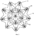
на фиг. 3 - вид в плане шарошки одного примера по настоящему изобретению;
на фиг. 4 - вид в плане шарошки другого примера по настоящему изобретению.The following is a detailed description of the present invention with reference to the drawings,
where in FIG. 1 is an incomplete section of a cone bit of one example of the present invention;
in FIG. 2 is a cone profile of one example of the present invention;
in FIG. 3 is a plan view of a cone of one example of the present invention;
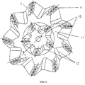
in FIG. 4 is a plan view of a cone of another example of the present invention.
На фиг. 1 показан неполный разрез шарошечного долота. Долото содержит лапу 1 и шарошку 3, лапа 1 с помощью цапфы консольного вала 2 на нижней части лапы соединяется с шарошкой 3. Цапфа 2 и отверстие внутри шарошки составляют подшипниковую пару, стопорные стальные шарики 5 подвижно соединяют шарошку 3 на цапфе 2, между стенкой отверстия шарошки и цапфой установлены тело качения 6 и уплотнительное кольцо 7. Последнее служит для предотвращения вытекания смазки изнутри подшипника и предотвращения вхождения рабочей жидкости в подшипник извне. В лапе имеется шпилька 8 для фиксации и стопорения стальных шариков 5. Отверстие 9 служит для заливания смазки в подшипник. In FIG. 1 shows an incomplete section of a cone bit. The bit contains a
Конструкция шарошки показана на фиг. 2 и 3. Внутри шарошки выполнено соединительное отверстие 13, которое вместе с цапфой лапы организует подшипниковую пару. Снаружи шарошка имеет прямые конусные зубцы, на шарошке выполнены зубчатые кольца 10 в двух ступенях - одно верхнее и одно нижнее. В такой конструкции, как в данном примере, на шарошке можно установить зубчатые кольца в 2-4 ступенях. Между ступенями выполнена кольцевая отделительная выемка 11, на каждом зубчатом кольце сделаны впадины 12, тем самым формируются зубцы зубчатого кольца. Зубцы представляют собой прямые конусы, направление зубца совпадает с направлением образующей конуса шарошки, на верху зубца зубчатого кольца по направлению зубца рядом установлены два вставных зуба 4, выполненных из твердого сплава и имеющих общепринятую форму. Вставные зубья можно выполнить и из других материалов с высокой твердостью и прочностью. Тело вставного зуба имеет форму цилиндра и имеет посадку с натягом с отверстием шарошки. Верхняя часть вставного зуба имеет клинообразную форму, промежуток между двумя вставными зубьями составляет 3 мм. The design of the cone is shown in FIG. 2 and 3. Inside the cutter, a connecting
Второй пример настоящего изобретения показан на фиг. 4. Основное отличие данного примера по сравнению с предыдущим заключается в том, что направление зубцов на зубчатом кольце отклоняется на некоторый угол α относительно образующей конуса шарошки, который составляет предпочтительно 5-15o. Шарошка содержит два зубчатых кольца 10. В такой конструкции шарошки, как в данном примере, можно установить зубчатые кольца в 2-4 ступенях. На верху каждого зубца зубчатого кольца верхней ступени по направлению этого зубца рядом вставлены два вставных зуба 4, на верху каждого зубца зубчатого кольца нижней ступени по направлению этого зубца рядом вставлены три вставных зуба, между двумя зубчатыми кольцами выполнена кольцевая отделительная выемка 11, на зубчатом кольце сделаны впадины 12.A second example of the present invention is shown in FIG. 4. The main difference of this example compared with the previous one is that the direction of the teeth on the toothed ring deviates by a certain angle α relative to the generatrix of the cone of the cone, which is preferably 5-15 o . The cone contains two
Преимущества конструкции с параллельно расположенными рядами с 2-3 зубцами с промежутком между ними от 2 до 5 мм заключаются в том, что будет более длинная режущая поверхность, и прерывистая головная поверхность, образованная длинными зубьями, позволяет легче углубляться в породу, что повышает производительность и срок службы долота. Промежуток между зубьями должен быть как можно меньше, что может придать конструкции функцию длинной режущей поверхности и ограничивается прочностными свойствами сплава, из которого выполнена шарошка. The advantages of the design with parallel rows with 2-3 teeth with a gap between them from 2 to 5 mm are that there will be a longer cutting surface, and the discontinuous head surface formed by long teeth makes it easier to go deep into the rock, which increases productivity and bit life The gap between the teeth should be as small as possible, which can give the structure the function of a long cutting surface and is limited by the strength properties of the alloy of which the cone is made.
Преимущество выбора величины угла между образующей конуса и направлением зубцов на зубчатом кольце, равного 5-15o, заключается в большей стабильности и эффективности во время резания по сравнению с прямым зубцом.The advantage of choosing the angle between the generatrix of the cone and the direction of the teeth on the toothed ring, equal to 5-15 o , is more stability and efficiency during cutting compared with a straight tooth.
Claims (8)
Applications Claiming Priority (2)
| Application Number | Priority Date | Filing Date | Title |
|---|---|---|---|
| CNB001146610A CN1174158C (en) | 2000-06-29 | 2000-06-29 | Roller bit with parallelly inlaid teeth |
| CN00114661.0 | 2000-06-29 |
Publications (2)
| Publication Number | Publication Date |
|---|---|
| RU2001112881A RU2001112881A (en) | 2003-04-20 |
| RU2206702C2 true RU2206702C2 (en) | 2003-06-20 |
Family
ID=4584308
Family Applications (1)
| Application Number | Title | Priority Date | Filing Date |
|---|---|---|---|
| RU2001112881/03A RU2206702C2 (en) | 2000-06-29 | 2001-05-15 | Insert rolling-cutter drilling bit |
Country Status (4)
| Country | Link |
|---|---|
| US (1) | US6595304B2 (en) |
| CN (1) | CN1174158C (en) |
| CA (1) | CA2331177C (en) |
| RU (1) | RU2206702C2 (en) |
Families Citing this family (10)
| Publication number | Priority date | Publication date | Assignee | Title |
|---|---|---|---|---|
| US7134959B2 (en) * | 2003-06-25 | 2006-11-14 | Scientific Games Royalty Corporation | Methods and apparatus for providing a lottery game |
| GB0521693D0 (en) * | 2005-10-25 | 2005-11-30 | Reedhycalog Uk Ltd | Representation of whirl in fixed cutter drill bits |
| US7885851B2 (en) * | 2005-11-17 | 2011-02-08 | Scientific Games International, Inc. | Retailer optimization using market segmentation top quintile process |
| US9074431B2 (en) | 2008-01-11 | 2015-07-07 | Smith International, Inc. | Rolling cone drill bit having high density cutting elements |
| CN102061886A (en) * | 2010-12-10 | 2011-05-18 | 湖南飞碟新材料有限责任公司 | Drill bit |
| US10337254B2 (en) * | 2015-12-04 | 2019-07-02 | PDB Tools, Inc. | Tungsten carbide insert bit with milled steel teeth |
| CN108222845B (en) * | 2018-04-09 | 2024-04-26 | 成都百施特金刚石钻头有限公司 | Annular cutting alloy tooth for drilling and production tool |
| CN108442879B (en) * | 2018-05-22 | 2023-07-04 | 西南石油大学 | Split drill bit with axial impact function |
| CN109469446A (en) * | 2019-01-25 | 2019-03-15 | 沧州格锐特钻头有限公司 | A kind of rock bit with chip removal structure |
| CN110259471A (en) * | 2019-07-23 | 2019-09-20 | 中交第三航务工程局有限公司 | Excavate to a kind of all standing the hobboing cutter cutter ring of ultra-clean hard rock shield machine |
Family Cites Families (32)
| Publication number | Priority date | Publication date | Assignee | Title |
|---|---|---|---|---|
| US3104726A (en) * | 1963-09-24 | Rotary blt stabilizing structure | ||
| US233746A (en) * | 1880-10-26 | Electric railway-signaling apparatus | ||
| US1896251A (en) * | 1929-12-20 | 1933-02-07 | Floyd L Scott | Cutter for well drills |
| US1847824A (en) * | 1930-06-14 | 1932-03-01 | Garber Tool Company | Rock bit cone |
| US1885085A (en) * | 1930-11-26 | 1932-10-25 | William F Dalzen | Rock drill |
| US1871736A (en) * | 1930-12-10 | 1932-08-16 | Chicago Pneumatic Tool Co | Tooth formation and arrangement for rotary drilling |
| US3003370A (en) * | 1956-07-05 | 1961-10-10 | Chicago Pneumatic Tool Co | Method of making rock bit cutter |
| US2927778A (en) * | 1956-07-05 | 1960-03-08 | Chicago Pneumatic Tool Co | Rotary drill cutters |
| US3098535A (en) * | 1960-09-23 | 1963-07-23 | Austin E Ragon | Tri-cone bit with inserts |
| US3442342A (en) * | 1967-07-06 | 1969-05-06 | Hughes Tool Co | Specially shaped inserts for compact rock bits,and rolling cutters and rock bits using such inserts |
| US4058177A (en) * | 1976-03-29 | 1977-11-15 | Dresser Industries, Inc. | Asymmetric gage insert for an earth boring apparatus |
| US4086973A (en) * | 1976-12-03 | 1978-05-02 | Dresser Industries, Inc. | Asymmetric insert for inner row of an earth boring cutter |
| US4108260A (en) * | 1977-04-01 | 1978-08-22 | Hughes Tool Company | Rock bit with specially shaped inserts |
| US4262761A (en) * | 1979-10-05 | 1981-04-21 | Dresser Industries, Inc. | Long-life milled tooth cutting structure |
| US4453836A (en) * | 1981-08-31 | 1984-06-12 | Klima Frank J | Sealed hard-rock drill bit |
| US4716977A (en) * | 1986-04-29 | 1988-01-05 | Dresser Industries, Inc. | Specially shaped cutting element for earth boring apparatus |
| EP0467870B1 (en) * | 1990-07-10 | 1995-01-25 | Smith International, Inc. | Roller tooth bit with heel row cutter inserts |
| US5201376A (en) * | 1992-04-22 | 1993-04-13 | Dresser Industries, Inc. | Rock bit with improved gage insert |
| US6209668B1 (en) * | 1993-07-08 | 2001-04-03 | Baker Hughes Incorporated | Earth-boring bit with improved cutting structure |
| GB9314954D0 (en) * | 1993-07-16 | 1993-09-01 | Camco Drilling Group Ltd | Improvements in or relating to torary drill bits |
| US5421423A (en) | 1994-03-22 | 1995-06-06 | Dresser Industries, Inc. | Rotary cone drill bit with improved cutter insert |
| GB9507703D0 (en) * | 1995-04-13 | 1995-05-31 | Camco Int | Flow channels |
| US6241034B1 (en) * | 1996-06-21 | 2001-06-05 | Smith International, Inc. | Cutter element with expanded crest geometry |
| US6059054A (en) * | 1996-06-21 | 2000-05-09 | Smith International, Inc. | Non-symmetrical stress-resistant rotary drill bit cutter element |
| US5967245A (en) * | 1996-06-21 | 1999-10-19 | Smith International, Inc. | Rolling cone bit having gage and nestled gage cutter elements having enhancements in materials and geometry to optimize borehole corner cutting duty |
| CA2244457C (en) * | 1997-08-05 | 2007-02-20 | Smith International, Inc. | Drill bit with ridge cutting cutter elements |
| US6561293B2 (en) * | 1997-09-04 | 2003-05-13 | Smith International, Inc. | Cutter element with non-linear, expanded crest |
| CA2246511A1 (en) * | 1997-09-04 | 1999-03-04 | Smith International, Inc. | Cutter element with non-rectilinear crest |
| US5979575A (en) * | 1998-06-25 | 1999-11-09 | Baker Hughes Incorporated | Hybrid rock bit |
| US6394199B1 (en) * | 1999-10-05 | 2002-05-28 | Schlumberger Technology Corp. | Non-circular gauge reaming row inserts |
| US6347676B1 (en) * | 2000-04-12 | 2002-02-19 | Schlumberger Technology Corporation | Tooth type drill bit with secondary cutting elements and stress reducing tooth geometry |
| US6688410B1 (en) * | 2000-06-07 | 2004-02-10 | Smith International, Inc. | Hydro-lifter rock bit with PDC inserts |
-
2000
- 2000-06-29 CN CNB001146610A patent/CN1174158C/en not_active Expired - Fee Related
-
2001
- 2001-01-16 CA CA002331177A patent/CA2331177C/en not_active Expired - Fee Related
- 2001-04-03 US US09/824,133 patent/US6595304B2/en not_active Expired - Lifetime
- 2001-05-15 RU RU2001112881/03A patent/RU2206702C2/en not_active IP Right Cessation
Also Published As
| Publication number | Publication date |
|---|---|
| US20020000335A1 (en) | 2002-01-03 |
| CA2331177A1 (en) | 2001-12-29 |
| US6595304B2 (en) | 2003-07-22 |
| CA2331177C (en) | 2006-12-12 |
| CN1331377A (en) | 2002-01-16 |
| CN1174158C (en) | 2004-11-03 |
Similar Documents
| Publication | Publication Date | Title |
|---|---|---|
| EP0467870B1 (en) | Roller tooth bit with heel row cutter inserts | |
| US4056153A (en) | Rotary rock bit with multiple row coverage for very hard formations | |
| CA2220679C (en) | Rolling cone bit with gage and off-gage cutter elements positioned to separate sidewall and bottom hole cutting duty | |
| US3269469A (en) | Solid head rotary-percussion bit with rolling cutters | |
| US5311958A (en) | Earth-boring bit with an advantageous cutting structure | |
| US5697462A (en) | Earth-boring bit having improved cutting structure | |
| RU2531720C2 (en) | Hybrid drilling bit with high side front inclination angle of auxiliary backup cutters | |
| US5752573A (en) | Earth-boring bit having shear-cutting elements | |
| CA2288923C (en) | High offset bits with super-abrasive cutters | |
| US6367569B1 (en) | Replaceable multiple TCI kerf ring | |
| EP1027521B1 (en) | Earth-boring bit having cutter with replaceable kerf ring with contoured inserts | |
| US4393948A (en) | Rock boring bit with novel teeth and geometry | |
| US2774570A (en) | Roller cutter for earth drills | |
| GB2316112A (en) | Rotary bit having shear cutting elements | |
| CA2348188C (en) | Rolling cone bit with elements fanned along the gage curve | |
| RU2206702C2 (en) | Insert rolling-cutter drilling bit | |
| GB2273726A (en) | Earth boring bit | |
| US4150728A (en) | Rock drill bit inserts with hollow bases | |
| CA2475719A1 (en) | Wedge tooth cutter element for drill bit | |
| US2648526A (en) | Rotary earth boring bit | |
| US4420050A (en) | Oil well drilling bit | |
| US5979575A (en) | Hybrid rock bit | |
| US7025155B1 (en) | Rock bit with channel structure for retaining cutter segments | |
| US4738323A (en) | Thrust bearing and cone locking assembly for rock drill bit | |
| CA1125500A (en) | Roller cutter |
Legal Events
| Date | Code | Title | Description |
|---|---|---|---|
| MM4A | The patent is invalid due to non-payment of fees |
Effective date: 20040516 |