RU2205507C1 - Noise suppressing device - Google Patents
Noise suppressing device Download PDFInfo
- Publication number
- RU2205507C1 RU2205507C1 RU2002110468/09A RU2002110468A RU2205507C1 RU 2205507 C1 RU2205507 C1 RU 2205507C1 RU 2002110468/09 A RU2002110468/09 A RU 2002110468/09A RU 2002110468 A RU2002110468 A RU 2002110468A RU 2205507 C1 RU2205507 C1 RU 2205507C1
- Authority
- RU
- Russia
- Prior art keywords
- input
- output
- block
- phase
- signal
- Prior art date
Links
Images
Landscapes
- Noise Elimination (AREA)
Abstract
Description
Устройство относится к радиотехнике и может найти применение в приемных устройствах. The device relates to radio engineering and may find application in receiving devices.
Известны устройства подавления помех, описанные в монографии "Теория обнаружения сигналов" под ред. Л. А. Бакута. М.: Радио и связь, 1984, с. 294-297, а также в журнале "Радиотехника", 8, 1984, с.33-35. Known interference suppression devices described in the monograph "Theory of signal detection", ed. L.A. Bakuta. M .: Radio and communications, 1984, p. 294-297, as well as in the journal "Radio Engineering", 8, 1984, pp. 33-35.
Недостатком устройств является малая степень подавления широкополосных фазоманипулированных помех. The disadvantage of the device is the low degree of suppression of broadband phase-shift interference.
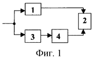
Наиболее близким по технической сущности к предлагаемому является устройство, описанное в статье В.П. Ефимова "Оценка нелинейного преобразования на помехоустойчивость приема в спутниковых сетях", опубликованной в журнале "Электромагнитные волны и электромагнитные системы", 1, т.3, 1998, с.95, принятое за прототип, структурная схема которого приведена на фиг.1, где обозначено:
1 - усилитель;
2 - вычитатель;
3 - ограничитель;
4 - полосовой фильтр.The closest in technical essence to the proposed is the device described in the article V.P. Efimova "Assessment of nonlinear conversion to noise immunity of reception in satellite networks", published in the journal "Electromagnetic waves and electromagnetic systems", 1, v.3, 1998, p.95, adopted as a prototype, the structural diagram of which is shown in figure 1, where indicated by:
1 - amplifier;
2 - subtractor;
3 - limiter;
4 - band-pass filter.
Устройство-прототип содержит последовательно соединенные усилитель 1 и вычитатель 2, выход которого является выходом устройства, а также последовательно соединенные ограничитель 3 и полосовой фильтр 4, выход которого соединен с вторым входом вычитателя 2, при этом входы усилителя 1 и ограничителя 3 объединены и являются входом устройства. The prototype device contains a series-connected
Устройство-прототип работает следующим образом. The prototype device operates as follows.
Входная смесь, содержащая сигнал и широкополосную помеху, с входа устройства поступает через блок 1, где осуществляется ее усиление, на первый вход вычитателя 2, на второй вход которого поступает оценка широкополосной помехи, которая формируется за счет ограничения входной смеси в блоке 3 с последующей фильтрацией результата ограничения в блоке 4. За счет вычитания в блоке 2 из входной смеси оценки широкополосной помехи на его выходе выделяется сигнал и нескомпенсированный остаток широкополосной помехи. The input mixture containing the signal and the broadband noise from the input of the device passes through
Недостатком прототипа является малая степень подавления широкополосных помех. The disadvantage of the prototype is the low degree of suppression of broadband interference.
Для устранения указанного недостатка в устройство подавления помех, содержащее последовательно соединенные ограничитель, вход которого является входом устройства, и полосовой фильтр, введены последовательно соединенные первый перемножитель, перестраиваемый режекторный фильтр, второй перемножитель и коммутатор, выход которого является выходом устройства, а также фазовый демодулятор, ключ и блок сравнения с порогом, выход которого соединен с третьим управляющим входом коммутатора и вторым управляющим входом ключа, выход которого соединен с вторым управляющим входом перестраиваемого режекторного фильтра. При этом выход полосового фильтра соединен с сигнальным входом фазового демодулятора, второй сигнальный выход которого соединен с вторыми опорными входами первого и второго перемножителей и с входом блока сравнения с порогом, а первый управляющий выход фазового демодулятора соединен с первым сигнальным входом ключа. Кроме того, первый сигнальный вход первого перемножителя и второй сигнальный вход коммутатора соединены с входом устройства. To eliminate this drawback, an interference suppression device containing a series-connected limiter, the input of which is the input of the device and a bandpass filter, introduces series-connected first multiplier, tunable notch filter, second multiplier and switch, the output of which is the output of the device, as well as a phase demodulator, a key and a comparison unit with a threshold, the output of which is connected to the third control input of the switch and the second control input of the key, the output of which is Inonii with a second control input of the tunable notch filter. The output of the bandpass filter is connected to the signal input of the phase demodulator, the second signal output of which is connected to the second reference inputs of the first and second multipliers and to the input of the comparison unit with a threshold, and the first control output of the phase demodulator is connected to the first signal input of the key. In addition, the first signal input of the first multiplier and the second signal input of the switch are connected to the input of the device.
Структурная схема предлагаемого устройства приведена на фиг.2, где приведены следующие обозначения:
1, 3 - первый и второй перемножители;
2 - перестраиваемый режекторный фильтр;
4 - коммутатор;
5 - ограничитель;
6 - полосовой фильтр;
7 - фазовый демодулятор;
8 - блок сравнения с порогом;
9 - ключ.The structural diagram of the proposed device is shown in figure 2, which shows the following notation:
1, 3 - the first and second multipliers;
2 - tunable notch filter;
4 - switch;
5 - limiter;
6 - band-pass filter;
7 - phase demodulator;
8 is a comparison block with a threshold;
9 is the key.
Предлагаемое устройство имеет следующие функциональные связи: последовательно соединенные первый перемножитель 1, перестраиваемый режекторный фильтр 2 и второй перемножитель 3, выход которого соединен с первым сигнальным входом коммутатора 4, выход которого является выходом устройства; последовательно соединенные ограничитель 5, полосовой фильтр 6 и фазовый демодулятор 7, первый управляющий выход которого соединен с первым сигнальным входом ключа 9, второй управляющий вход ключа 9 соединен с выходом блока сравнения с порогом 8 и с третьим управляющим входом коммутатора 4, второй сигнальный вход которого соединен с первым сигнальным входом первого перемножителя 1, с входом ограничителя 5 и является входом устройства; кроме того, второй сигнальный выход фазового демодулятора 7 соединен с вторыми опорными входами первого 1 и второго 3 перемножителей и с входом блока сравнения с порогом 8, а выход ключа 9 соединен с вторым управляющим входом перестраиваемого режекторного фильтра 2. The proposed device has the following functional relationships: sequentially connected the
Предлагаемое устройство работает следующим образом. The proposed device operates as follows.
Входная смесь, содержащая сигнал и широкополосную фазоманипулированную помеху, с входа устройства подается на последовательно соединенные блоки 5 и 6, где за счет ограничения в блоке 5 с последующей фильтрацией результата ограничения в блоке 6 происходит подавление мощной фазоманипулированной помехой более слабого сигнала. С выхода блока 6 входная смесь, в которой подавлен сигнал, поступает на сигнальный вход блока 7, где за счет ее демодуляции на втором сигнальном выходе блока 7 выделяется псевдослучайная последовательность помехи, которая подается на вторые, опорные, входы блоков 1 и 3. В блоке 1 за счет перемножения входной смеси с псевдослучайной последовательностью помехи осуществляется свертка широкополосной фазоманицулированной помехи на ее несущую частоту, которая режектируется блоком 2. В то же время на полезный сигнал в блоке 1 накладывается манипуляция псевдослучайной последовательностью помехи, которая затем снимается в блоке 3 за счет перемножения с той же псевдослучайной последовательностью. Таким образом, на выходе блока 3 выделяется только сигнал, который подается на выход устройства через блок 4 при условии подачи на его третий управляющий вход команды "1", свидетельствующей об обнаружении широкополосной фазоманипулированной помехи. The input mixture containing the signal and the broadband phase-shifted noise from the device input is fed to blocks 5 and 6 connected in series, where due to the restriction in block 5 and the subsequent filtering of the restriction result in block 6, the weaker phase-signal is suppressed by the powerful phase-manipulated noise. From the output of block 6, the input mixture, in which the signal is suppressed, goes to the signal input of block 7, where due to its demodulation, a pseudo-random interference sequence is allocated at the second signal output of block 7, which is fed to the second, reference, inputs of
Обнаружение широкополосной фазоманипулированной помехи осуществляется в блоке 8, на вход которого со второго сигнального выхода блока 7 подается ее псевдослучайная последовательность. Одновременно команда об обнаружении помехи ("1") с выхода блока 8 подается на второй управляющий вход блока 9, отпирая его и обеспечивая прохождение через него напряжения, формируемого блоком 7 на его первом управляющем выходе. Это напряжение через открытый блок 9 подается на второй управляющий вход блока 2, обеспечивая настройку блока 2 на частоту несущей широкополосной фазоманипулированной помехи, за счет чего обеспечивается режекция несущей широкополосной фазоманипулированной помехи не только в случае совпадения ее частоты с частотой несущей сигнала, но и в случаях ее отличия. The detection of broadband phase-manipulated interference is carried out in block 8, the input of which from the second signal output of block 7 is its pseudo-random sequence. At the same time, a command to detect interference ("1") from the output of block 8 is sent to the second control input of block 9, unlocking it and ensuring the passage of voltage through it generated by block 7 at its first control output. This voltage, through open block 9, is supplied to the second control input of
Таким образом, за счет подачи управляющего напряжения с первого, управляющего, выхода блока 7 через блок 9 на управляющий выход блока 2, обеспечивается изменение частоты настройки блока 2 в соответствии с изменением частоты несущей широкополосной фазоманипулированной помехи в случае ее обнаружения в блоке 8. Thus, by supplying a control voltage from the first, control, output of block 7 through block 9 to the control output of
При отсутствии превышения порога в блоке 8 на его выходе формируется команда "0", которая запирает блок 9, запрещая прохождение напряжения на управляющий вход блока 2, при отсутствии которого блок 2 настроен на частоту несущей сигнала. Одновременно команда "0", подаваемая на третий управляющий вход блока 4, подключает через блок 4 вход устройства на его выход. В этом случае компенсация широкополосной фазоманипулированной помехи не осуществляется. In the absence of exceeding the threshold in block 8, an “0” command is generated at its output, which blocks block 9, prohibiting the passage of voltage to the control input of
Обнаружение фазоманипулированной помехи в блоке 8 выполняется за счет сравнения его входного напряжения с порогом. The detection of phase-manipulated interference in block 8 is performed by comparing its input voltage with a threshold.
В случае превышения порога на выходе блока 8 формируется команда "1". In case of exceeding the threshold at the output of block 8, the command "1" is generated.
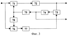
Вариант структурной схемы блока 7 приведен на фиг.3, где обозначено:
71, 73 и 76 - первый, второй и третий перемножители;
72, 74 и 77 - первый, второй и третий фильтры нижних частот;
75 - перестраиваемый генератор;
78 - фазовращатель на 90o.A variant of the structural diagram of block 7 is shown in figure 3, where it is indicated:
71, 73 and 76 - the first, second and third multipliers;
72, 74 and 77 - the first, second and third low-pass filters;
75 - tunable generator;
78 - phase shifter 90 o .
Блок 7 содержит последовательно соединенные первый перемножитель 71 и первый фильтр нижних частот 72, выход которого соединен с первым сигнальным входом второго перемножителя 73, являющимся сигнальным выходом блока 7; последовательно соединенные третий перемножитель 76 и третий фильтр нижних частот 77, выход которого соединен с вторым сигнальным входом второго перемножителя 73, выход которого соединен с последовательно соединенными вторым фильтром нижних частот 74 и перестраиваемым генератором 75, выход которого соединен с вторым опорным входом первого перемножителя 71 непосредственно, а через фазовращатель на 90o - с вторым опорным входом третьего перемножителя 76, первый сигнальный вход которого соединен с первым сигнальным входом первого перемножителя 71, который является входом устройства; кроме того, выход второго фильтра нижних частот 74 соединен с вторым управляющим выходом блока 7.Block 7 contains a series-connected
Блок 7 представляет собой известный демодулятор Костаса (см. Диксон Р.К. Широкополосные системы. М.: Связь, 1979, с.149, рис.5.20, где приведено описание его работы. Block 7 is a well-known costas demodulator (see Dixon R.K. Broadband systems. M: Communication, 1979, p.149, Fig.5.20, for a description of its operation.
Отличие фиг.3 от упомянутого демодулятора Костаса заключается в том, что выход блока 74 подается не только на вход перестраиваемого генератора 75, но и на выход блока 7. The difference between FIG. 3 and said Costas demodulator is that the output of
Управляющее напряжение, используемое для изменения частоты перестраиваемого генератора 75, одновременно используется для синхронного изменения частоты настройки блока 2. The control voltage used to change the frequency of the
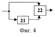
Блок 2 может быть выполнен так, как это представлено на фиг.4:
21 - перестраиваемый полосовой фильтр;
22 - вычитатель.
21 - tunable band-pass filter;
22 is a subtractor.
Блок 2 содержит последовательно соединенные перестраиваемый полосовой фильтр 21 и вычитатель 22, при этом вход блока 2 соединен с первым входом блока 22 непосредственно, а с вторым его входом - через блок 21, выход блока 22 является выходом блока 2.
Блок 21 может быть выполнен в виде параллельного контура, в котором емкость выполнена в виде конденсатора, параллельно которому включен варикап, на который подается управляющее напряжение с второго выхода блока 7. В соответствии с этим управляющим напряжением изменяется емкость варикапа, за счет чего изменяется частота настройки блока 21 и, следовательно, блока 2.
Полоса пропускания блока 6 выбирается больше полосы спектра широкополосной фазоманипулированной помехи на величину, определяемую диапазоном возможного изменения частоты ее несущей. The bandwidth of block 6 is selected more than the bandwidth of the spectrum of the broadband phase-shift interference by an amount determined by the range of possible changes in the frequency of its carrier.
В прототипе наибольшая степень подавления широкополосной фазоманипулированной помехи достигается в том случае, когда ее амплитуда равна уровню ограничения ограничителя. In the prototype, the greatest degree of suppression of the broadband phase-shift interference is achieved when its amplitude is equal to the limit level of the limiter.
В случае воздействия на устройство-прототип помех с разными амплитудами степень их подавления будет снижаться по мере отличия их амплитуды от уровня ограничения ограничителя. Кроме того, в условиях многолучевости появляется паразитная амплитудная модуляция помех. В то же время амплитуды оценок помех остаются постоянными, равными уровню ограничения. Поэтому в условиях многолучевости степень подавления широкополосных фазоманипулированных помех снижается. In the case of interference with different amplitudes on a prototype device, the degree of their suppression will decrease as their amplitude differs from the limiter limit level. In addition, in multipath conditions, spurious amplitude modulation of interference appears. At the same time, the amplitudes of the interference estimates remain constant, equal to the level of limitation. Therefore, in the conditions of multipath, the degree of suppression of broadband phase-shift interference is reduced.
При воздействии амплитудно-модулированных сигналов на ограничитель паразитная амплитудная модуляция переходит в паразитную фазовую модуляцию, что также снижает степень подавления широкополосных фазоманипулированных помех в прототипе. When the amplitude-modulated signals act on the limiter, spurious amplitude modulation goes into spurious phase modulation, which also reduces the degree of suppression of broadband phase-shifted interference in the prototype.
Кроме того, степень подавления помех за счет их компенсации лежит в пределах 20÷40 дБ. In addition, the degree of interference suppression due to their compensation lies in the range of 20–40 dB.
В заявляемом устройстве используется режекция широкополосной фазоманипулированной помехи с использованием выделенной псевдослучайной последовательности помехи и обеспечением изменения частоты настройки режекторного фильтра в соответствии с изменением частоты несущей помехи. За счет этого обеспечивается не только повышение степени подавления широкополосных фазоманипулированных помех до величин порядка 60-80 дБ, но и независимость ее от таких факторов, как многолучевость тракта и изменение частоты несущей. The inventive device uses rejection of a broadband phase-manipulated interference using a dedicated pseudo-random interference sequence and providing a change in the tuning frequency of the notch filter in accordance with a change in the frequency of the carrier interference. This ensures not only an increase in the degree of suppression of broadband phase-shifted interference to values of about 60-80 dB, but also its independence from such factors as multipath path and the change in carrier frequency.
Claims (1)
Priority Applications (1)
| Application Number | Priority Date | Filing Date | Title |
|---|---|---|---|
| RU2002110468/09A RU2205507C1 (en) | 2002-04-19 | 2002-04-19 | Noise suppressing device |
Applications Claiming Priority (1)
| Application Number | Priority Date | Filing Date | Title |
|---|---|---|---|
| RU2002110468/09A RU2205507C1 (en) | 2002-04-19 | 2002-04-19 | Noise suppressing device |
Publications (1)
| Publication Number | Publication Date |
|---|---|
| RU2205507C1 true RU2205507C1 (en) | 2003-05-27 |
Family
ID=20255606
Family Applications (1)
| Application Number | Title | Priority Date | Filing Date |
|---|---|---|---|
| RU2002110468/09A RU2205507C1 (en) | 2002-04-19 | 2002-04-19 | Noise suppressing device |
Country Status (1)
| Country | Link |
|---|---|
| RU (1) | RU2205507C1 (en) |
-
2002
- 2002-04-19 RU RU2002110468/09A patent/RU2205507C1/en not_active IP Right Cessation
Similar Documents
| Publication | Publication Date | Title |
|---|---|---|
| US4992747A (en) | Multiple reuse of an FM band | |
| RU2205507C1 (en) | Noise suppressing device | |
| RU2248097C2 (en) | Method for transmitting information | |
| RU2205501C2 (en) | Narrow-band noise suppressing device for broadband signal receivers | |
| RU2287899C1 (en) | Multiplicative device for narrow-band noise protection | |
| RU2197063C2 (en) | Device for suppressing broadband phase-keyed noise | |
| RU2209512C2 (en) | Structural noise suppression device | |
| RU2073954C1 (en) | Device for correlation processing of broad-band signals | |
| RU2210861C1 (en) | Signal receiving device using pseudorandom operating frequency control | |
| RU2153768C2 (en) | Device for noise compensation | |
| SU1698998A1 (en) | Device for correlational signal processing | |
| RU2293439C2 (en) | Receiver of radio-impulse signals with frequency-time encoding | |
| SU1628213A1 (en) | Composite multifrequency signal synchronizer | |
| US11621701B2 (en) | Filter that minimizes in-band noise and maximizes detection sensitivity of exponentially-modulated signals | |
| RU2219656C2 (en) | Method for receiving signals involving pseudorandom frequency tuning | |
| RU2233026C1 (en) | Noise rejection device | |
| RU2267226C1 (en) | Device for detection and frequency estimation of radio pulses | |
| RU2197062C2 (en) | Broadband phase-keyed noise compensator | |
| RU2157049C1 (en) | Device for compensating noise in broad band receivers | |
| RU2007872C1 (en) | Device for correlation processing of wide-band signals | |
| RU2166231C2 (en) | Noise compensating device for phase-keyed broadband signal receiver | |
| RU2204202C2 (en) | Device for suppressing broadband phase-keyed noise | |
| RU2204203C1 (en) | Narrow-band noise suppression device | |
| SU743209A1 (en) | Adaptive radio noise suppressor | |
| RU2248088C1 (en) | Band filter automatic tuning device |
Legal Events
| Date | Code | Title | Description |
|---|---|---|---|
| MM4A | The patent is invalid due to non-payment of fees |
Effective date: 20050420 |