RU2201373C2 - Hatch opening and closing device - Google Patents
Hatch opening and closing device Download PDFInfo
- Publication number
- RU2201373C2 RU2201373C2 RU2001112702A RU2001112702A RU2201373C2 RU 2201373 C2 RU2201373 C2 RU 2201373C2 RU 2001112702 A RU2001112702 A RU 2001112702A RU 2001112702 A RU2001112702 A RU 2001112702A RU 2201373 C2 RU2201373 C2 RU 2201373C2
- Authority
- RU
- Russia
- Prior art keywords
- cavity
- rod
- hydraulic cylinder
- valve
- piston
- Prior art date
Links
- 239000012530 fluid Substances 0.000 claims abstract description 29
- 230000007246 mechanism Effects 0.000 claims description 9
- 239000013535 sea water Substances 0.000 claims description 6
- 238000004891 communication Methods 0.000 claims description 4
- 230000003993 interaction Effects 0.000 claims description 4
- 239000000463 material Substances 0.000 claims description 3
- 238000007599 discharging Methods 0.000 claims 1
- 238000011089 mechanical engineering Methods 0.000 abstract description 6
- 239000000126 substance Substances 0.000 abstract 1
- 230000011664 signaling Effects 0.000 description 12
- 230000000903 blocking effect Effects 0.000 description 6
- 238000013461 design Methods 0.000 description 5
- 238000009434 installation Methods 0.000 description 5
- 230000007797 corrosion Effects 0.000 description 3
- 238000005260 corrosion Methods 0.000 description 3
- 230000009471 action Effects 0.000 description 2
- 239000000956 alloy Substances 0.000 description 2
- 229910045601 alloy Inorganic materials 0.000 description 2
- 230000006835 compression Effects 0.000 description 2
- 238000007906 compression Methods 0.000 description 2
- 239000007788 liquid Substances 0.000 description 2
- 238000011022 operating instruction Methods 0.000 description 2
- 210000000056 organ Anatomy 0.000 description 2
- 230000007704 transition Effects 0.000 description 2
- 244000273618 Sphenoclea zeylanica Species 0.000 description 1
- 230000001133 acceleration Effects 0.000 description 1
- 238000009825 accumulation Methods 0.000 description 1
- 238000013459 approach Methods 0.000 description 1
- 238000006073 displacement reaction Methods 0.000 description 1
- 230000005611 electricity Effects 0.000 description 1
- 238000005516 engineering process Methods 0.000 description 1
- 230000005284 excitation Effects 0.000 description 1
- 229920002313 fluoropolymer Polymers 0.000 description 1
- 230000007774 longterm Effects 0.000 description 1
- 238000012423 maintenance Methods 0.000 description 1
- 239000002184 metal Substances 0.000 description 1
- 230000001681 protective effect Effects 0.000 description 1
- 230000002441 reversible effect Effects 0.000 description 1
- 238000007789 sealing Methods 0.000 description 1
- 230000035939 shock Effects 0.000 description 1
- 239000007787 solid Substances 0.000 description 1
- 125000006850 spacer group Chemical group 0.000 description 1
- 230000001360 synchronised effect Effects 0.000 description 1
- 238000013022 venting Methods 0.000 description 1
- 238000004804 winding Methods 0.000 description 1
Images
Landscapes
- Actuator (AREA)
Abstract
Description
Изобретение относится к машиностроению, в частности к устройствам для открывания и закрывания люков подвижными щитами или крышками, и может быть применено как в судостроении для открывания-закрывания люковыми закрытиями (щитами, крышками) люков, так и в других областях техники, где необходимо производить открывание-закрывание проемов, люков. The invention relates to mechanical engineering, in particular to devices for opening and closing manholes with movable shields or covers, and can be applied both in shipbuilding for opening and closing manhole covers (shields, covers) of manholes, and in other areas of technology where it is necessary to open -closing openings, hatches.
Известно устройство для открывания и закрывания люка (заявка Японии 49-25714, МКИ В 63 b 19/14, 1974 г.), содержащее четыре гидравлических цилиндра (ГЦ), установленных по четырем углам под крышкой люка для ее поднимания и опускания. Во внутренней части люкового закрытия установлен гидравлический усилитель, который подключен к трубопроводу с жидкостью под давлением, установленному внутри корпуса судна. Для работы гидравлического усилителя установлен вспомогательный танк (бак). Давление жидкости, которая поступает из вспомогательного танка, усиливается в гидравлическом усилителе и передается через гидравлические цилиндры на крышку люка, заставляя ее открываться или закрываться. A device for opening and closing the hatch (Japanese application No. 49-25714, MKI B 63
Недостатком данного устройства является использование большого количества (четырех) исполнительных механизмов (ГЦ) для открывания и закрывания крышки люка, а также большое количество гидроаппаратуры (гидроусилитель, дополнительный танк), что увеличивает массогабаритные характеристики устройства. The disadvantage of this device is the use of a large number of (four) actuators (HZ) for opening and closing the manhole cover, as well as a large number of hydraulic equipment (power steering, additional tank), which increases the overall dimensions of the device.
Кроме того, известное устройство недостаточно надежно, так как в нем отсутствуют сигнализаторы открытого-закрытого положения крышки люка, что усложняет обслуживание данного устройства в морской акватории в штормовых условиях, так как на пульте управления (ПУ) судна отсутствуют сигнальные лампы, сигнализирующие о закрытом-открытом положении крышки люка. In addition, the known device is not reliable enough, since there are no signaling devices for the open-closed position of the hatch, which complicates the maintenance of this device in the sea in stormy conditions, since the control panel (PU) of the vessel does not have signal lights that signal closed open position of the manhole cover.
Кроме того, устройство не позволяет последовательно производить несколько рабочих операций, например открывание-закрывание люка и выдвижение из него рабочего органа. In addition, the device does not allow sequentially to perform several operations, for example, opening-closing the hatch and the extension of the working body.
Известно устройство для открывания и закрывания дверей на паромном судне (заявка 48-32831 Японии, МКИ В 63 b 19/08, 1973 г.). Устройство содержит гидропривод с гидроцилиндром, соединенным с дверью, и блокировочное устройство в виде отдельного гидроцилиндра с рычагом. В этом устройстве дверь нижним концом прикреплена с помощью петель к корпусу паромного судна, верхний конец двери связан с помощью каната с цилиндром простого действия, установленным в пределах борта судна. В закрытом положении дверь поднята вверх благодаря гидравлическому приводу при соответствующем положении распределительного клапана, в открытом положении дверь свободно опущена вниз под действием собственного веса. К корпусу паромного судна прикреплен блокировочный рычаг для фиксации двери в ее закрытом положении. Один конец блокировочного рычага упирается в шток блокировочного цилиндра, который имеет внутри пружину и жестко прикреплен к корпусу судна. Другой конец блокировочного стержня сделан в виде крючка и в закрытом положении двери имеет зацепление со стопорной скобой, установленной на двери, причем в этом положении рычаг удерживается под действием пружины блокировочного цилиндра, осуществляя блокировку двери в ее закрытом положении. При наличии давления в блокировочном цилиндре блокировка может быть снята. Когда дверь находится вблизи своего крайнего верхнего положения, давление в блокировочном цилиндре выше, чем давление в приводном цилиндре. При необходимости снятия блокировки распределительный клапан соединяет трубопровод от приводного насоса одновременно с приводным и блокировочным цилиндрами. Когда дверь находится в открытом положении, трубопровод от блокировочного цилиндра перекрывается с помощью распределительного клапана, а трубопровод от приводного цилиндра подключается к приводному насосу. Данное устройство по заявке Японии 48-32831 выбрано в качестве наиболее близкого аналога. A device is known for opening and closing doors on a ferry ship (Japanese application 48-32831, MKI B 63
В данном устройстве, в отличие от предыдущего аналога, для совершения полезной работы по открыванию-закрыванию двери задействованы два рабочих органа: ГЦ прямого действия по открыванию-закрыванию двери и блокировочный ГЦ, который препятствует самопроизвольному открыванию двери. In this device, in contrast to the previous analogue, two working bodies are involved to perform useful work on opening and closing a door: a direct-acting HZ for opening and closing a door and a locking HZ that prevents the door from opening spontaneously.
В описанном аналоге также отсутствуют сигнализаторы конечного положения люкового закрытия (двери), необходимые при эксплуатации двери, особенно в ненастную штормовую погоду для оповещения командного состава судна о закрытом или открытом положении двери, что ведет к снижению эксплуатационной надежности устройства, особенно в штормовых условиях. Кроме того, это устройство не позволяет последовательно производить и открывание-закрывание люка, и, например, выдвижение рабочего органа, для его выдвижения потребуется еще один исполнительный механизм, при этом величина массогабаритных характеристик из-за наличия двух самостоятельных гидроприводов и гидравлически управляемой аппаратуры увеличивается, что крайне нежелательно. The described analogue also lacks end position indicators for hatch closing (doors), which are necessary during door operation, especially in inclement stormy weather, to notify the crew of a ship about a closed or open door position, which leads to a decrease in the operational reliability of the device, especially in stormy conditions. In addition, this device does not allow sequentially opening and closing the hatch, and, for example, extending the working body, it requires another actuator to extend it, while the size and weight characteristics increase due to the presence of two independent hydraulic drives and hydraulically controlled equipment, which is highly undesirable.
В машиностроении известны блокировочные устройства - клапаны (см. книгу: Эксплуатация и наладка гидросистем металлорежущих станков/ Под ред. М.М. Кузнецова и А.С. Шашкина. М.: Машиностроение, 1965, с. 99), которые относятся к контрольно-регулирующей аппаратуре гидросистемы и применяются для блокировки потока рабочей жидкости в гидросистеме, а именно для выключения или включения новых контуров гидросистемы. Блокировочные клапаны находятся раздельно от ГЦ и имеют между собой связь только через трубопровод гидросистемы. In mechanical engineering, locking devices are known as valves (see the book: Operation and adjustment of hydraulic systems of metal cutting machines / Edited by MM Kuznetsov and AS Shashkina. M: Mechanical Engineering, 1965, p. 99), which are referred to as a control -regulating equipment of the hydraulic system and are used to block the flow of the working fluid in the hydraulic system, namely, to turn off or on the new hydraulic circuit. Blocking valves are located separately from the HZ and are interconnected only through the hydraulic system pipeline.
В машиностроении известны устройства для открывания-закрывания коммуникаций между источником давления и цепью потребителя - электромагнитные краны (см. книгу: Гидравлические механизмы/ Под ред. Ж. Фезандье. М.: Оборонгиз, 1960, с. 133-134). В этих кранах управление по открытию-закрытию движения рабочей жидкости осуществляется посредством электромагнита малой мощности. При отсутствии возбуждения в обмотке электромагнита игла вспомогательного клапана прижимается к своему седлу одной пружиной, сам клапан прижат к своему седлу другой пружиной, в этом положении масло под давлением не может попасть в систему потребителя. При включении тока в электромагнит сердечник основного клапана втягивается внутрь электромагнита, приподнимает иглу вспомогательного клапана, и масло под давлением попадает под поршень электромагнитного крана, открывая основной клапан к потребителю. In mechanical engineering, devices are known for opening and closing communications between a pressure source and a consumer circuit - electromagnetic cranes (see book: Hydraulic Mechanisms / Ed. By J. Fesandier. M .: Oborongiz, 1960, pp. 133-134). In these taps, the control for opening and closing the movement of the working fluid is carried out by means of a low power electromagnet. In the absence of excitation in the electromagnet winding, the auxiliary valve needle is pressed to its seat with one spring, the valve itself is pressed to its seat with another spring, in this position oil under pressure cannot get into the consumer system. When the current is turned into an electromagnet, the core of the main valve is drawn into the electromagnet, lifts the needle of the auxiliary valve, and oil under pressure falls under the piston of the electromagnetic valve, opening the main valve to the consumer.
Известный электромагнитный кран также находится отдельно от ГЦ, а для работы данного крана нужен также подвод дополнительного источника электроэнергии. The well-known electromagnetic crane is also located separately from the HZ, and for the operation of this crane you also need the supply of an additional source of electricity.
Известны путевые переключатели (сигнализаторы) мгновенного действия типа ВК и ВПК по МРТУ-16-528.006-69 и ГОСТ 18134-72, ГОСТ 18147-72 для включения-отключения электрической цепи при совершении рабочего цикла рабочим органом, которые устанавливаются на устройствах с подвижными рабочими органами в непосредственной близости от них и с непосредственным контактом самих путевых переключателей с деталями подвижных органов (см. книгу: Справочник конструктора-машиностроителя/ Под ред. В. И. Анурьева. М.: Машиностроение, 1973, т. 2, с. 556-565). Known directional switches (signaling devices) of instantaneous operation such as VK and VPK according to MRTU-16-528.006-69 and GOST 18134-72, GOST 18147-72 for turning on / off the electric circuit when the duty cycle is completed by the working body, which are installed on devices with moving workers organs in close proximity to them and with direct contact of the track switches themselves with the details of the movable organs (see book: Handbook of a mechanical engineer / Ed. V.I. Anuryev. M: Mechanical Engineering, 1973, v. 2, p. 556 -565).
Недостатком этих сигнализаторов является их малая эксплуатационная надежность из-за непосредственного механического контакта деталей сигнализатора с деталями рабочего органа. А так как они устанавливаются в непосредственной близости с рабочим органом, то возникают сложности при их эксплуатации из-за трудности доступа к ним, особенно в малогабаритных помещениях в забортном исполнении в подводном судостроении. The disadvantage of these signaling devices is their low operational reliability due to direct mechanical contact of the signaling device parts with the working body parts. And since they are installed in close proximity to the working body, difficulties arise in their operation due to the difficulty of access to them, especially in small-sized rooms in outboard versions in underwater shipbuilding.
Известны бесконтактные сигнализаторы типа УСПК по ТУ 5.668-8208-76, предназначенные для выдачи электрических сигналов при достижении подвижными рабочими органами различных механизмов заданных положений, которые тоже устанавливаются в зоне работы рабочих органов и применяются в судостроении в комплекте преобразователя электрических сигналов УСПК-П и элемента управления УСПК-ЭУ (см. техническое описание и инструкцию по эксплуатации MX 3.604.060TO). Contactless signaling devices of the USPK type according to TU 5.668-8208-76 are known, designed to issue electric signals when the moving working bodies reach various mechanisms of the specified positions, which are also installed in the working area of the working bodies and are used in shipbuilding as a set of electric signal converter USPK-P and element USPK-EU control (see the technical description and operating instructions MX 3.604.060TO).
Сигнализаторы типа УСПК не воспринимают на себя механические удары, нежели переключатели типа ВК и ВПК, но так же устанавливаются вблизи работы подвижных механизмов, что неудобно при эксплуатации их в стесненных помещениях в забортном исполнении в подводном судостроении. USPK type signaling devices do not take mechanical shocks on themselves than VK and VPK type switches, but are also installed near the operation of movable mechanisms, which is inconvenient when used in cramped rooms in outboard versions in underwater shipbuilding.
Задача заявляемого устройства заключается в расширении его эксплуатационных возможностей и сокращении массогабаритных характеристик путем обеспечения одним исполнительным механизмом двух последовательных функций, например открывание люка и выдвижение антенны мачтового устройства. The objective of the claimed device is to expand its operational capabilities and reduce weight and size characteristics by providing one actuator for two sequential functions, such as opening the hatch and extending the antenna of the mast device.
Задача заключается также в обеспечении надежности работы устройства и удобстве его эксплуатации. The task is also to ensure the reliability of the device and the convenience of its operation.
Поставленная задача решена тем, что шток гидроцилиндра выполнен полым, с переходной частью, выполненной в области задней крышки, и полукольцами, установленными по периметру торца штока со стороны передней крышки, блокировочное устройство выполнено в виде клапана цилиндрической формы, расположенного в упомянутой полости и в полости передней крышки; передняя крышка сообщена с полостью второго рабочего органа, а между передней крышкой и поршнем установлено седло, к торцу которого со стороны передней крышки подпружинен торец клапана, расположенного с возможностью продольного перемещения в седле с зазором; клапан имеет две головки, одна из которых прижата к седлу со стороны поршневой полости, другая расположена в области задней крышки с возможностью взаимодействия с полукольцами с одной стороны и с переходной частью штоковой полости - с другой, устройство сигнализации выполнено в виде элемента управления сигнализаторами, соединенного со штоком и взаимодействующего с преобразователями сигналов, закрепленными на корпусе гидроцилиндра на расстоянии друг от друга, равном ходу поршня. The problem is solved in that the hydraulic cylinder rod is made hollow, with a transitional part made in the region of the rear cover and half rings installed around the perimeter of the rod end from the front cover side, the locking device is made in the form of a cylindrical valve located in the cavity and in the cavity front cover; the front cover is in communication with the cavity of the second working body, and a saddle is installed between the front cover and the piston, to the end of which from the front cover side a valve end face is located, which can be longitudinally moved in the saddle with a gap; the valve has two heads, one of which is pressed to the saddle from the side of the piston cavity, the other is located in the rear cover region with the possibility of interaction with the half rings on the one hand and with the transitional part of the rod cavity on the other, the alarm device is made in the form of an alarm control element connected with a rod and interacting with signal converters mounted on the cylinder body at a distance from each other, equal to the piston stroke.
Кроме того, шток соединен с элементом управления сигнализаторами посредством вилки, один конец которой соединен с ползуном, на котором закреплен упомянутый элемент управления, другой - закреплен на штоке за пределами задней крышки, при этом ползун размещен в направляющей, установленной параллельно оси гидроцилиндра. In addition, the rod is connected to the control element of the signaling devices by means of a plug, one end of which is connected to a slider on which the said control element is fixed, the other is fixed to the rod outside the rear cover, while the slider is placed in a guide mounted parallel to the axis of the hydraulic cylinder.
Кроме того, зазор между поверхностями седла и клапана в центральном отверстии седла выполнен в виде канавок (пазов) на поверхности клапана. In addition, the gap between the surfaces of the seat and valve in the Central hole of the seat is made in the form of grooves (grooves) on the surface of the valve.
Кроме того, полукольца установлены в штоковой полости на торце штока при помощи штифтов. In addition, the half rings are installed in the rod cavity at the end of the rod using pins.
Кроме того, корпус гидроцилиндра имеет обтекаемую форму и выполнен из материала, не корродирующего в морской воде. In addition, the body of the hydraulic cylinder is streamlined and made of a material that does not corrode in sea water.
Кроме того, задняя крышка гидроцилиндра с наружной стороны имеет конусообразную форму. In addition, the rear cover of the hydraulic cylinder has a conical shape on the outside.
Кроме того, переходная часть штоковой полости и головка блокировочного клапана, взаимодействующая с ней, выполнены конусообразной формы. In addition, the transitional part of the rod cavity and the head of the blocking valve interacting with it are conical in shape.
Новая конструкция позволит расширить эксплуатационные возможности устройства путем обеспечения одним исполнительным механизмом двух последовательных функций, например открывание люка и последовательное выдвижение антенны мачтового устройства. При этом сокращаются также массогабаритные характеристики устройства в целом за счет выполнения штока гидроцилиндра полым и размещения в этой полости и в полости передней крышки, сообщенной с полостью второго рабочего органа, блокировочного устройства, выполненного в виде клапана цилиндрической формы, расположенного в упомянутой полости соосно с полостью передней крышки, с возможностью продольного перемещения. The new design will expand the operational capabilities of the device by providing one actuator with two sequential functions, for example, opening the hatch and sequential extension of the antenna of the mast device. At the same time, the overall dimensions of the device as a whole are also reduced due to the hollow of the hydraulic cylinder rod and placement of a locking device made in the form of a cylindrical valve located in the cavity in alignment with the cavity in this cavity and in the cavity of the front cover in communication with the cavity of the second working member front cover, with the possibility of longitudinal movement.
Новая конструкция устройства позволит повысить надежность устройства и удобство его эксплуатации за счет выполнения устройства сигнализации в виде элемента управления и преобразователей электрических сигналов, размещенных не вблизи рабочих органов, а непосредственно на корпусе ГЦ и штоке соответственно, причем элемент управления соединен со штоком с возможностью взаимодействия с преобразователями электрических сигналов, закрепленных на корпусе гидроцилиндра на расстоянии друг от друга, равном ходу поршня. The new design of the device will improve the reliability of the device and the convenience of its operation due to the implementation of the signaling device in the form of a control element and electrical signal converters, located not near the working bodies, but directly on the main body and stem, respectively, the control element being connected to the rod with the possibility of interaction converters of electrical signals mounted on the housing of the hydraulic cylinder at a distance from each other, equal to the stroke of the piston.
Новая конструкция позволит избежать коррозии гидроцилиндра в морской воде за счет выполнения корпуса гидроцилиндра из материала, не корродирующего в морской воде, а также позволит эксплуатировать его в ледовых условиях благодаря выполнению задней крышки гидроцилиндра с наружной стороны конусообразной формы. The new design will avoid corrosion of the hydraulic cylinder in sea water due to the design of the cylinder body from a material that does not corrode in sea water, and will also allow it to be operated in ice conditions by performing the rear cylinder cover on the outside of the conical shape.
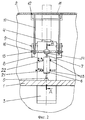
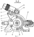
Устройство представлено чертежами, где:
на фиг.1 изображен общий вид устройства для открывания-закрывания люка;
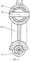
на фиг.2 - вид сбоку на устройство;
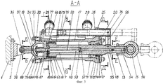
на фиг.3 - разрез А-А на фиг.2 (гидроцилиндр в продольном разрезе);
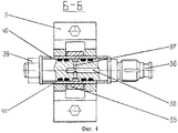
на фиг. 4 - разрез Б-Б на фиг.3 (подвод рабочей жидкости ко второму изделию);
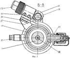
на фиг.5 - разрез В-В на фиг.3 (гидроцилиндр в поперечном разрезе);
на фиг. 6 - разрез В-В на фиг.3 (гидроцилиндр в поперечном разрезе, исполнение с лапами);
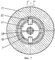
на фиг.7 - разрез Г-Г на фиг.3 (поперечный разрез штока с блокировочным клапаном и изображением полуколец);
на фиг. 8 - разрез Д-Д на фиг.3 (поперечный разрез штока с изображением вилки и ползуна);
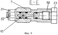
На фиг. 9 - разрез Е-Е на фиг.3 (поперечный разрез штока с изображением штуцера для выхода воздуха).The device is represented by drawings, where:
figure 1 shows a General view of the device for opening and closing the hatch;
figure 2 is a side view of the device;
figure 3 is a section aa in figure 2 (hydraulic cylinder in longitudinal section);
in FIG. 4 - section BB in figure 3 (supply of working fluid to the second product);
figure 5 is a section bb in figure 3 (hydraulic cylinder in cross section);
in FIG. 6 - section bb in figure 3 (hydraulic cylinder in cross section, execution with paws);
in Fig.7 is a section GG in Fig.3 (cross section of a rod with a blocking valve and an image of half rings);
in FIG. 8 - section DD in figure 3 (cross section of the rod with the image of the plug and slide);
In FIG. 9 is a cross-section EE in FIG. 3 (cross section of a rod with an image of a fitting for air outlet).
Устройство для открывания-закрывания люка (см. фиг.1) размещено между основным (прочным) корпусом 1 и легким корпусом 2 подводного плавсредства. В основном корпусе 1 выполнена шахта 3, соединенная с дополнительным рабочим органом (далее - рабочим органом), например гидромотором (на чертеже не показан) выдвижения антенны 4 мачтового устройства. A device for opening and closing the hatch (see figure 1) is placed between the main (durable) body 1 and the light body 2 of the underwater craft. In the main body 1, a
На основном корпусе 1, на шарнирной опоре 5, установлен исполнительный механизм, гидроцилиндр (ГЦ) 6 с подвижным штоком 7. На корпусе шахты 3 жестко установлены симметрично два кронштейна (рычага) 8 с пазами на свободных концах для шарнирного крепления в них посредством осей 9 кронштейнов (рычагов) 10 (см. фиг.1 и 2), являющихся принадлежностью люкового закрытия - щита 11. Щит 11 установлен в легком корпусе 2, в люке 12, с зазором и уплотнением по его контуру. On the main body 1, on the
Шток 7 за пределами корпуса ГЦ 6 выполнен с резьбой (см. фиг.3), с помощью которой контргайкой 13 на штоке 7 закреплена головка 14. Головка 14 имеет отверстие, ось которого перпендикулярна оси штока 7 для шарнирного соединения с валом 15. Вал 15 (см. фиг.2) на своих концах имеет шарнирные соединения с кронштейнами (рычагами) 10 и удерживается на них от осевого смещения посредством гаек 16. The
Исполнительный механизм (привод), единый для перемещения щита 11 и приведения в действие рабочего органа, например гидромотора для выдвижения антенны 4 мачтового устройства, представляет собой ГЦ 6 двустороннего действия (см. фиг. 3 и 5), включающий корпус 17, шток 7 с поршнем 18, переднюю 19 и заднюю 20 крышки. Корпус 17 выполнен из сплава 3М по ОСТ В5Р. 9325-79 обтекаемой формы, что позволяет эксплуатировать его в забортном исполнении в морской воде без коррозии и шума при движении судна с ускорением в морской акватории. На наружных боковых поверхностях корпуса 17, симметрично его оси, со стороны передней крышки 19 установлен штуцер 21 подвода рабочей среды из гидросистемы (на чертеже не показано), например жидкости ПГВ ГОСТ 25821-83, и штуцер 22 отвода рабочей среды в гидросистему (см. фиг. 2). С противоположной стороны штуцерам 21 и 22 (см. фиг.5) установлены два штуцера 23 отвода воздуха из рабочих полостей ГЦ 6. Корпус 17 ГЦ может быть установлен не на шарнирной опоре, а на лапах 24 (см. фиг.6) - как другое исполнение - с отверстиями на них для крепления к фундаменту (прочному корпусу 1). Корпус 17 со стороны задней крышки 20 имеет жестко прикрепленную к нему направляющую 25, имеющую отверстие для установки в нем ползуна 26. An actuator (drive), the only one for moving the
На корпусе 17 ГЦ 6 (см. фиг.5) рядом с местами расположения штуцеров 21 и 22 имеются кронштейны 27 для крепления к ним преобразователей электрических сигналов 28 и 29 устройства сигнализации (см. фиг.5, 6) посредством, например, болтов 30, гаек 31. Преобразователи электрических сигналов 28 и 29, например типа УСПК-П по ТУ 5.668-8208-76, служат для выдачи электрических сигналов на ПУ командного состава судна о нахождении штока 7 в своих крайних точках, что соответствует полному открытию или закрытию щита 11. On the
Передняя крышка 19 установлена на торце корпуса 17, например, посредством шпилек 32 (см. фиг.3), гаек 33 и шайб 34. Крышка 19 выполнена с отверстием 37, сообщенным с проушиной 35, на торце, на свободном конце которой имеется также отверстие, в котором шарнирно установлена ось 36 (см. фиг. 4). В оси 36 выполнено отверстие 38 для подачи рабочей жидкости к рабочему органу, например к гидромотору для выдвижения антенны 4 мачтового устройства, а также сливу жидкости обратно в гидросистему (на чертеже не показана). Ось 36 закреплена на проушине 35 посредством гайки 39 (см. фиг.4) через проставки 40 и имеет герметичное уплотнение в виде резиновых колец 41 по ОСТ В38.0529-86. Ось 36 (см. фиг.1) через герметичное штуцерное соединение и трубопровод 42 соединена через штуцер 43 с шахтой 3 для подачи рабочей жидкости к рабочему органу, например к гидромотору для выдвижения из шахты 3 антенны 4 мачтового устройства. Крышка 19 установлена герметично на корпусе 17 через уплотнительную прокладку 44 и резиновые кольца 45 по ОСТ В38.0529-86. В случае исполнения ГЦ на лапах (см. фиг.6) крышка 19 имеет штуцер 46 на глухой стенке для подвода рабочей среды к рабочему органу в шахту 3. The
На заднем торце корпуса 17 установлена задняя крышка 20, имеющая центральное сквозное отверстие для прохода штока 7. Крышка 20 прикреплена к корпусу 17, например посредством шпилек 32, гаек 33 и шайб 34, и имеет герметичное уплотнение в виде прокладки 44 и грязесъемника 47, который служит для очистки грязи с поверхности штока 7. Крышка 20 с наружной стороны, по периметру отверстия под шток 7, выполнена конусной формы для скола с поверхности штока 7 кусочков льда, образующихся при эксплуатации судна в условиях Крайнего Севера. At the rear end of the
Шток 7 установлен вдоль оси корпуса 17 и выполнен из сплава 3М ОСТ 1-92077-91 с целью избежания коррозии в морской воде. Шток 7 выполнен полым с полостью малого сечения 48, переходящей в полость 49 большего сечения в районе задней крышки. Со стороны задней крышки 20, за пределами корпуса 17, шток 7 имеет отверстие (см. фиг.9) для установки штуцера 50 с целью отвода воздуха из полостей 48 и 49. The
Штуцер 50 герметично установлен посредством резиновых колец 45 и закреплен на штоке 7 посредством корончатой гайки 51 и шплинта 52. Для выпуска воздуха из штуцера 50 последний имеет пробку 53, установленную в штуцере 50 посредством резьбы. Полость 48 малого сечения на конце штока 7 закрыта герметично заглушкой 54 (см. фиг.3). Рядом со штуцером 50 на наружной поверхности штока 7 выполнена канавка 55 для установки в ней вилки 56. Полость 48 переходит в полость 49 при помощи переходной части 57 конусной формы. Внутри полости 49 большого сечения установлено блокировочное устройство в виде клапана 58, имеющего две головки, одну - 59 с конусной поверхностью для контакта с конусной поверхностью переходной части 57 полости штока 7 с одной стороны и с полукольцами 61 с другой стороны, другую - 60 в виде шайбы. Два полукольца 61 удерживаются на штоке 7 посредством двух штифтов 62 (см. фиг. 7). Со стороны передней крышки 19 на штоке 7 установлен поршень 18, имеющий герметичное уплотнение с внутренней стенкой корпуса 17 в виде резиновых колец 63 и шайб 64 по ОСТ В38.0529-86. Внутренняя поверхность корпуса 17 обработана до шероховатости 0,63-0,32 мкм по шкале Ra ГОСТ 2789-73 с целью контакта с наружной поверхностью поршня 18 и совершения перемещения поршня 18 без задиров и заеданий. Поршень 18 укреплен на штоке 7 такими же штифтами 62, что и полукольца 61. Шток 7 для установки поршня 18 имеет буртик 65, а поршень 18 имеет проточку 66 меньшего диаметра для подачи рабочей среды в поршневую полость корпуса 17. The fitting 50 is sealed by means of rubber rings 45 and secured to the
Между торцами передней крышки 19 и штока 7 установлено седло 67, имеющее по оси корпуса 17 сквозное отверстие для установки в нем с возможностью продольного перемещения клапана 58, имеющего ход в полости штока 5-10 мм (расстояние между торцом цилиндрической головки 60 блокировочного клапана и седлом 67). На цилиндрической поверхности клапана 58 в зоне сквозного отверстия седла 67 выполнен зазор в виде продольных канавок (пазов) для прохода рабочей среды через отверстие в седле 67 из поршневой полости ГЦ 6 в полость крышки 19. Седло 67 имеет две цилиндрические поверхности: большого диаметра - для герметичной установки внутри корпуса 17 и малого диаметра - для установки пружины 68. Седло 67 со стороны расположения штока 7 имеет две торцевые поверхности: большого диаметра - контактирующего с торцом штока 7, малого диаметра - для контакта с рабочим торцом головки 60 клапана 58. В полости передней крышки 19, на самом конце клапана 58, перпендикулярно оси клапана 58 выполнено сквозное отверстие для установки шплинта 69, а последний - для установки шайбы 70 с целью упора в нее свободного торца пружины 68, работающей на сжатие, а другой торец пружины 68 опирается о внутренний торец седла 67. Between the ends of the
Внутри корпуса 17, в зоне расположения крышки 20, имеется втулка 71, предназначенная для установки в ней штока 7. Втулка 71 имеет герметичное уплотнение посредством колец 63 и шайб 64 по ОСТ 38.0529-86, таких же, что и для уплотнения поршня 18, а также манжеты 72 по ОСТ В38.0536-87 с защитной шайбой 73 из фторопласта марки Ф4 по ОСТ В6-05-5022-81 и кольца подманжетного 74. Inside the
Вилка 56 служит для закрепления в ней ползуна 26, например, с помощью штифта 75 (см. фиг.8). Ползун 26 выполнен трубчатого сечения, поэтому вилка 56 имеет в зоне крепления ползуна 26 цилиндрическую форму. Ползун 26 установлен в направляющей 25 (см. фиг.3) и предназначен для синхронного перемещения в ней вместе со штоком 7. Направляющая 25 имеет отверстие круглой формы для подвижной установки в этом отверстии ползуна 26. Ползун 26, на противоположном торце от вилки 56, имеет резьбовую втулку 76 для крепления с помощью резьбы элемента управления 77, например типа УСПК-Э по ТУ 5-668-8208-76. The
Элемент управления 77 после настройки своего положения относительно преобразователей 28 и 29 с целью выдачи электрических сигналов, фиксируется на ползуне 26 посредством, например, установочного винта 78. The control element 77 after adjusting its position relative to the
Устройство для открывания-закрывания люка работает следующим образом. A device for opening and closing the hatch operates as follows.
При необходимости открывания люкового закрытия с ПУ командирского состава судна подается электрический сигнал для включения гидростанции (на чертеже не показана) и подачи через общую гидросистему (на чертежах не показана) рабочей среды, например жидкости ПГВ, к штуцеру 21 ГЦ 6 (см. фиг.1 и 2). Рабочая жидкость через штуцер 21 проходит внутрь корпуса 17 и попадает в поршневую проточку 66 (см. фиг.3) и под усилием давления рабочей жидкости перемещает поршень 18 со штоком 7 вправо, к втулке 71. При движении штока 7 вместе с ним движется и головка 14 (см. фиг.2), заставляя перемещаться вал 15 вверх (см. фиг.1) относительно осей 9 кронштейнов 8, приводя в движение щит 11 посредством кронштейнов 10. При этом слив рабочей жидкости из запоршневой полости в гидросистему (на чертеже не показана) из ГЦ 6 происходит через штуцер 22 (см. фиг.2). If it is necessary to open the hatchway from the control system of the commanding officer, an electrical signal is supplied to turn on the hydraulic power station (not shown in the drawing) and supply a working medium, for example, PGV fluid, to the
При перемещении штока 7 вправо (см. фиг.3) перемещается и вилка 56 вправо и через ползун 26 отводит элемент управления 77 от преобразователя 28 электрических сигналов, который подает электрический сигнал (на чертеже не показано) по электропроводам на ПУ командного состава судна, где лампочка, сигнализирующая о закрытом положении щита 11, гаснет. При этом клапан 58, за счет осевого усилия пружины 68, левым торцом головки 60 прижат к правому торцу седла 67, препятствуя поступлению рабочей жидкости в полость крышки и затем к рабочему органу. По мере приближения поршня 18 к втулке 71 полукольца 61 (см. фиг.3 и 7) своими торцами упираются в торец головки 59 клапана 58, преодолевая при этом усилие пружины сжатия 68, и начинают перемещать клапан 58 в канале 49 штока 7 до момента упора конусной головки 59 клапана 58 в конусную опорную поверхность переходной части 57 штока 7. При этом головка 60 клапана 58 отходит от торца седла 67, зазор между поверхностью клапана 58 и седлом 67 открывается и через продольные канавки клапана 58 дает возможность рабочей жидкости перетекать из поршневой рабочей полости в полость передней крышки 19. Далее рабочая жидкость через каналы 37 и 38 в оси 36 начинает поступать через трубопровод 42 и штуцер 43 к рабочему органу, например к гидромотору для выдвижения из шахты 3 антенны мачтового устройства (на чертеже не показано). When the
При упоре поршня 18 в торец втулки 71 движение штока 7 прекращается, слив рабочей жидкости через штуцер 22 (см. фиг.2) также прекращается. Вилка 56 выдвинута вправо на длину полного рабочего хода поршня 18 и штока 7, что соответствует полному открытию щита 11. При этом ползун 26 переместил в направляющей 25 элемент управления 77 до места установки преобразователя 29 электрических сигналов. При пересечении магнитного поля преобразователя 29 магнитными силовыми линиями элемента управления 77 в преобразователе 29 возникает электрический импульс, который подает по электропроводам (на чертеже не показано) электрический сигнал (электрический ток) на ПУ командного состава о нахождении щита 11 в полностью открытом положении. И только после полного открывания щита 11 подается рабочая жидкость от гидросистемы в необходимом объеме через центральное отверстие в седле 67 во внутреннюю полость передней крышки 19, далее через каналы 37 и 38 (см. фиг.4) оси 36 к трубопроводу 42, штуцеру 43 шахты 3, к рабочему органу, например к гидромотору (на чертеже не показано) для выдвижения антенны 4 мачтового устройства. When the
Обратная операция по убиранию антенны 4 мачтового устройства и закрыванию щита 11 осуществляется следующим образом. The reverse operation of removing the
Через распределительный клапан гидросистемы (на чертеже не показано) рабочая жидкость подается к штуцеру 22 ГЦ 6 (см. фиг.2), а через штуцер 21 происходит слив рабочей жидкости в гидросистему. От ПУ (на чертеже не показан) командного состава судна подается электрический сигнал на опускание антенны 4 мачтового устройства. Through the control valve of the hydraulic system (not shown in the drawing), the working fluid is supplied to the nozzle 22 of the hydraulic cylinder 6 (see figure 2), and through the
Гидромотор (на чертежах не показан) антенны 4 мачтового устройства работает на ее опускание в пределах шахты 3, при этом через штуцер 43 (см. фиг. 1), трубопровод 42, каналы 38 и 37 (см. фиг.3 и 4) происходит слив рабочей жидкости через переднюю крышку 19 и штуцер 21 ГЦ 6 (см. фиг.2) в гидросистему (на чертежах не показана). The hydraulic motor (not shown) of the
Только после слива рабочей жидкости от шахты 3, от рабочего органа - гидромотора антенны 4 мачтового устройства в гидросистему рабочая жидкость подается к штуцеру 22, приводя в движение шток 7, помогая пружине перемещать клапан 58 к седлу 67. Only after draining the working fluid from the
Под действием осевого усилия пружины 68 (см.фиг.3) клапан 58 перемещается влево к седлу 67 и перекрывает торцом головки 60 центральное отверстие в седле 67, в результате чего слив рабочей жидкости из шахты 3, от рабочего органа в ГЦ 6 прекращается. Under the action of the axial force of the spring 68 (see Fig. 3), the
Рабочая жидкость через штуцер 22 (см. фиг.2) поступает в запоршневую рабочую полость и перемещает с усилием шток 7 справа - налево к передней крышке 19, при этом происходит слив рабочей жидкости через штуцер 21. При разобщении магнитных силовых линий в элементе управления 77 (см. фиг.3) с магнитными силовыми линиями преобразователя 29 электрических сигналов последний выдает сигнал в электрическую цепь (на чертежах не показано) о начале закрывания щитом 11 люка 12 в легком корпусе 2 (см. фиг.1). На ПУ (на чертеже не показан) командного состава судна гаснет лампочка о наличии щита 11 в открытом положении. The working fluid through the nozzle 22 (see figure 2) enters the piston working cavity and moves the
При движении поршня 18 к передней крышке 19 шток 7 через головку 14 (см. фиг. 1 и 2) воздействует на вал 15 и перемещает последний вниз к основному корпусу 1, заставляя кронштейны 10 щита 11 вращаться относительно осей 9, в результате чего щит 11 перемещается вверх к люку 12 корпуса 2. Как только поршень 18 достигнет торцевой стенки седла 67 (см. фиг.3) слив рабочей жидкости из ГЦ 6 через штуцер 21 прекращается. Одновременно вилка 56 через направляющую 25 с помощью ползуна 26 перемещает элемент управления 77 к преобразователю 28 электрических сигналов. При этом магнитное силовое поле преобразователя 28 пересекается с магнитными силовыми линиями элемента управления 77, в результате чего от преобразователя 28 на ПУ (на чертеже не показан) командного состава судна поступает по электрическим проводам (на чертеже не показано) электрический сигнал о нахождении щита 11 в положении "Закрыто". Одновременно подача рабочей жидкости к штуцеру 22 (см. фиг.2) прекращается, и оба штуцера 21 и 22 ГЦ 6 устанавливаются распределительным клапаном гидросистемы (на чертежах не показано) в положение "Закрыто". В случае накопления в ГЦ 6 при его длительной эксплуатации внутри корпуса 17 избыточного воздуха, последний стравливается через штуцеры 23 (см. фиг.5 и 6). When the
Далее цикл работы устройства повторяется. Next, the cycle of the device is repeated.
Предлагаемое устройство позволяет с помощью одного исполнительного механизма - гидроцилиндра со штоком, соединенным посредством рычажного механизма с люковым закрытием - щитом и имеющим блокировочное устройство, выполненное в виде клапана, установленного в полости штока ГЦ и сообщающего поршневую полость ГЦ с полостью дополнительного рабочего органа, осуществить несколько последовательных функций: перемещение щита, закрывающего люк, и, например, выдвижение-опускание антенны мачтового устройства, обеспечив при этом надежную последовательность в работе этих механизмов: вначале открывание щитом люка, а затем выдвижение антенны мачтового устройства, что обеспечивает эксплуатационную надежность устройства, а также уменьшает его массогабаритные характеристики за счет сокращения количества исполнительных механизмов и размещения блокировочного устройства внутри полого штока. The proposed device allows using one actuator - a hydraulic cylinder with a rod connected by a lever mechanism with a hatch - a shield and having a locking device made in the form of a valve installed in the cavity of the cylinder head and communicating the piston cavity of the cylinder with a cavity of an additional working body, to carry out several successive functions: moving the shield covering the hatch, and, for example, extending and lowering the antenna of the mast device, while ensuring a reliable atelnost in these mechanisms: first shield hatch opening, and then the antenna mast extension device that provides the operational reliability of the device and reduces its weight and size by reducing the number of actuators of the locking device and placing within said hollow stem.
Установка преобразователей электрических сигналов конечного положения штока непосредственно на корпусе ГЦ, а элемента управления ими - на штоке, а не на самих движущихся механизмах (щите и т.п.), как это принято, позволяет также повысить надежность работы устройства за счет обеспечения надежной сигнализации на ПУ судна, при этом не произойдет поломки сигнализатора из-за непосредственного контакта движущегося механизма (щита и т.п.) с корпусами сигнализаторов, устанавливаемых по известной схеме вблизи движущихся механизмов или на них (см. книгу: Справочник конструктора-машиностроителя/ под ред. В. И. Анурьева. М.: Машиностроение, 1973, с. 554-565, см. ТУ 5.668-8208-76, "Техническое описание и инструкция по эксплуатации" МХ3.604.060ТО). The installation of electrical signal converters of the final position of the rod directly on the cylinder head body, and their control element on the rod, and not on the moving mechanisms themselves (shield, etc.), as is customary, also allows to increase the reliability of the device by providing reliable signaling on the ship’s PU, in this case, the signaling device will not break down due to direct contact of the moving mechanism (shield, etc.) with the signaling devices housings installed according to the known scheme near or on moving mechanisms (see Nigu: Handbook of a mechanical engineer / edited by V.I. Anuryev, Moscow: Mashinostroenie, 1973, p. 554-565, see TU 5.668-8208-76, "Technical description and operating instructions" MX3.604.060TO )
Claims (8)
Priority Applications (1)
| Application Number | Priority Date | Filing Date | Title |
|---|---|---|---|
| RU2001112702A RU2201373C2 (en) | 2001-05-08 | 2001-05-08 | Hatch opening and closing device |
Applications Claiming Priority (1)
| Application Number | Priority Date | Filing Date | Title |
|---|---|---|---|
| RU2001112702A RU2201373C2 (en) | 2001-05-08 | 2001-05-08 | Hatch opening and closing device |
Publications (1)
| Publication Number | Publication Date |
|---|---|
| RU2201373C2 true RU2201373C2 (en) | 2003-03-27 |
Family
ID=20249465
Family Applications (1)
| Application Number | Title | Priority Date | Filing Date |
|---|---|---|---|
| RU2001112702A RU2201373C2 (en) | 2001-05-08 | 2001-05-08 | Hatch opening and closing device |
Country Status (1)
| Country | Link |
|---|---|
| RU (1) | RU2201373C2 (en) |
Cited By (8)
| Publication number | Priority date | Publication date | Assignee | Title |
|---|---|---|---|---|
| RU2268191C1 (en) * | 2004-06-28 | 2006-01-20 | Федеральное Государственное Унитарное Предприятие "Санкт-Петербургское Морское Бюро Машиностроения "Малахит" | Device for cracking-open access hatch cover |
| RU2299829C1 (en) * | 2005-12-21 | 2007-05-27 | Федеральное Государственное Унитарное Предприятие "Санкт-Петербургское Морское Бюро Машиностроения "Малахит" | Shipboard hydraulic drive |
| RU2303173C1 (en) * | 2005-12-21 | 2007-07-20 | Федеральное Государственное Унитарное Предприятие "Санкт-Петербургское Морское Бюро Машиностроения "Малахит" | Hydraulic drive |
| RU2317224C1 (en) * | 2006-07-06 | 2008-02-20 | Федеральное государственное унитарное предприятие "Центральное конструкторское бюро морской техники "Рубин" | Hatch cover opening device |
| RU2364542C1 (en) * | 2008-04-08 | 2009-08-20 | Открытое акционерное общество "Конструкторское бюро специального машиностроения" | Hydraulic drive for hatch covers |
| CN102897285A (en) * | 2012-10-23 | 2013-01-30 | 中国舰船研究设计中心 | Hydraulic watertight hatch cover device capable of opening and closing automatically |
| RU193224U1 (en) * | 2019-02-11 | 2019-10-17 | Акционерное общество "Научно-производственное предприятие "Старт" им. А.И. Яскина" | RUNNING-CLOSING DEVICE FOR RUNNING UNIT COVER |
| CN113428294A (en) * | 2021-07-22 | 2021-09-24 | 无锡市欣帆船舶设备有限公司 | Control method, system, device and medium for large-scale vertical jacking hydraulic hatch cover |
-
2001
- 2001-05-08 RU RU2001112702A patent/RU2201373C2/en not_active IP Right Cessation
Cited By (10)
| Publication number | Priority date | Publication date | Assignee | Title |
|---|---|---|---|---|
| RU2268191C1 (en) * | 2004-06-28 | 2006-01-20 | Федеральное Государственное Унитарное Предприятие "Санкт-Петербургское Морское Бюро Машиностроения "Малахит" | Device for cracking-open access hatch cover |
| RU2299829C1 (en) * | 2005-12-21 | 2007-05-27 | Федеральное Государственное Унитарное Предприятие "Санкт-Петербургское Морское Бюро Машиностроения "Малахит" | Shipboard hydraulic drive |
| RU2303173C1 (en) * | 2005-12-21 | 2007-07-20 | Федеральное Государственное Унитарное Предприятие "Санкт-Петербургское Морское Бюро Машиностроения "Малахит" | Hydraulic drive |
| RU2317224C1 (en) * | 2006-07-06 | 2008-02-20 | Федеральное государственное унитарное предприятие "Центральное конструкторское бюро морской техники "Рубин" | Hatch cover opening device |
| RU2364542C1 (en) * | 2008-04-08 | 2009-08-20 | Открытое акционерное общество "Конструкторское бюро специального машиностроения" | Hydraulic drive for hatch covers |
| CN102897285A (en) * | 2012-10-23 | 2013-01-30 | 中国舰船研究设计中心 | Hydraulic watertight hatch cover device capable of opening and closing automatically |
| CN102897285B (en) * | 2012-10-23 | 2015-03-11 | 中国舰船研究设计中心 | Hydraulic watertight hatch cover device capable of opening and closing automatically |
| RU193224U1 (en) * | 2019-02-11 | 2019-10-17 | Акционерное общество "Научно-производственное предприятие "Старт" им. А.И. Яскина" | RUNNING-CLOSING DEVICE FOR RUNNING UNIT COVER |
| CN113428294A (en) * | 2021-07-22 | 2021-09-24 | 无锡市欣帆船舶设备有限公司 | Control method, system, device and medium for large-scale vertical jacking hydraulic hatch cover |
| CN113428294B (en) * | 2021-07-22 | 2022-03-01 | 无锡市欣帆船舶设备有限公司 | Control method, system, device and medium for large-scale vertical jacking hydraulic hatch cover |
Similar Documents
| Publication | Publication Date | Title |
|---|---|---|
| US4665653A (en) | Ship's door or hatch arrangement | |
| RU2201373C2 (en) | Hatch opening and closing device | |
| CA1273328A (en) | Dual stage hydraulic actuator for expanding gate valve | |
| CA2297296C (en) | Multi-dump metering valve | |
| AU2012201273B2 (en) | Improved multi-dump metering valve | |
| EP1119690A4 (en) | Hydraulically-assisted engine valve actuator | |
| EP1415104A1 (en) | Valve system and method | |
| CN105947156A (en) | Lifting device for ship sonar | |
| KR100859332B1 (en) | Steering device with multi-stage hydraulic supply structure | |
| US6152792A (en) | Steering and reversing apparatus for waterjet propulsion systems | |
| US4577654A (en) | Fluid actuated pipeline valve | |
| CN211498956U (en) | Escape well lid assembly | |
| US5924379A (en) | Actuating mechanism with improved mounting structure | |
| KR100980130B1 (en) | submarine | |
| CN107264750B (en) | Lifting device for underwater detector | |
| JPS60501154A (en) | Propeller propulsion device mounting parts | |
| CN111516842A (en) | Ship lateral propeller pipe tunnel watertight device | |
| WO1987002094A1 (en) | Shut-down valve | |
| US4288059A (en) | Sluice gate | |
| CN213776415U (en) | High-pressure-resistance leakage-proof two-way electromagnetic valve | |
| GB2226103A (en) | Pipeline gate valve | |
| NL2007377C2 (en) | Marine shell door including hydraulic actuator unit. | |
| CN113137485A (en) | Integrated side valve | |
| RU2317224C1 (en) | Hatch cover opening device | |
| WO1998020257A1 (en) | Inverted accumulator |
Legal Events
| Date | Code | Title | Description |
|---|---|---|---|
| MM4A | The patent is invalid due to non-payment of fees |
Effective date: 20100509 |
|
| NF4A | Reinstatement of patent |
Effective date: 20121210 |
|
| PC43 | Official registration of the transfer of the exclusive right without contract for inventions |
Effective date: 20130131 |
|
| MM4A | The patent is invalid due to non-payment of fees |
Effective date: 20200509 |