RU2201034C2 - Uncoordinated multiple-user frequency-jump wireless pico-cell system - Google Patents
Uncoordinated multiple-user frequency-jump wireless pico-cell system Download PDFInfo
- Publication number
- RU2201034C2 RU2201034C2 RU2000109553/09A RU2000109553A RU2201034C2 RU 2201034 C2 RU2201034 C2 RU 2201034C2 RU 2000109553/09 A RU2000109553/09 A RU 2000109553/09A RU 2000109553 A RU2000109553 A RU 2000109553A RU 2201034 C2 RU2201034 C2 RU 2201034C2
- Authority
- RU
- Russia
- Prior art keywords
- address
- devices
- master
- slave
- nodes
- Prior art date
Links
Images


Classifications
-
- H—ELECTRICITY
- H04—ELECTRIC COMMUNICATION TECHNIQUE
- H04W—WIRELESS COMMUNICATION NETWORKS
- H04W84/00—Network topologies
- H04W84/18—Self-organising networks, e.g. ad-hoc networks or sensor networks
- H04W84/20—Master-slave selection or change arrangements
-
- H—ELECTRICITY
- H04—ELECTRIC COMMUNICATION TECHNIQUE
- H04B—TRANSMISSION
- H04B1/00—Details of transmission systems, not covered by a single one of groups H04B3/00 - H04B13/00; Details of transmission systems not characterised by the medium used for transmission
- H04B1/69—Spread spectrum techniques
- H04B1/713—Spread spectrum techniques using frequency hopping
- H04B1/7143—Arrangements for generation of hop patterns
-
- H—ELECTRICITY
- H04—ELECTRIC COMMUNICATION TECHNIQUE
- H04W—WIRELESS COMMUNICATION NETWORKS
- H04W40/00—Communication routing or communication path finding
- H04W40/02—Communication route or path selection, e.g. power-based or shortest path routing
- H04W40/04—Communication route or path selection, e.g. power-based or shortest path routing based on wireless node resources
-
- H—ELECTRICITY
- H04—ELECTRIC COMMUNICATION TECHNIQUE
- H04W—WIRELESS COMMUNICATION NETWORKS
- H04W40/00—Communication routing or communication path finding
- H04W40/24—Connectivity information management, e.g. connectivity discovery or connectivity update
- H04W40/30—Connectivity information management, e.g. connectivity discovery or connectivity update for proactive routing
-
- H—ELECTRICITY
- H04—ELECTRIC COMMUNICATION TECHNIQUE
- H04W—WIRELESS COMMUNICATION NETWORKS
- H04W8/00—Network data management
- H04W8/22—Processing or transfer of terminal data, e.g. status or physical capabilities
- H04W8/24—Transfer of terminal data
-
- H—ELECTRICITY
- H04—ELECTRIC COMMUNICATION TECHNIQUE
- H04W—WIRELESS COMMUNICATION NETWORKS
- H04W8/00—Network data management
- H04W8/26—Network addressing or numbering for mobility support
Abstract
Description
Предшествующий уровень техники
Изобретение относится к некоординированным беспроводным системам, более конкретно к самоорганизующейся связности в некоординированной беспроводной многопользовательской системе.State of the art
The invention relates to uncoordinated wireless systems, and more particularly to self-organizing connectivity in an uncoordinated wireless multi-user system.
Локальные сети радиосвязи в типовом случае охватывают область техники, в которой объединяются компьютерная индустрия и индустрия беспроводной связи. Обычные компьютерные сети основываются на проводных локальных сетях, в типовом случае использующих коммутацию пакетов и предназначенных для передачи данных. В противоположность этому, беспроводные сети, в частности сотовые сети, основываются на распределенных сетях, в типовом случае используют коммутацию каналов и предназначены для передачи речевых сигналов. Большинство технических решений, используемых при проектировании локальных сетей радиосвязи, повторяют принципы, которые используются в проводных локальных сетях. Это, однако, вызывает проблемы, поскольку условия передачи в проводной среде и в беспроводной среде различаются весьма существенным образом. Более того, мультимедийные передачи требуют реализации дополнительных свойств, ввиду особых требований к характеристикам трафика, выдвигаемых необходимостью передачи данных, речи и видеосигналов. Наконец, среда передачи в домашних условиях имеет свои собственные требования, которые могут быть решающими при проектировании системы. Radio local area networks typically cover a technical field in which the computer industry and the wireless communications industry are combined. Conventional computer networks are based on wired local area networks, which typically use packet switching to transmit data. In contrast, wireless networks, in particular cellular networks, are based on distributed networks, typically use circuit switching and are designed to transmit speech signals. Most of the technical solutions used in the design of local radio networks repeat the principles that are used in wired local networks. This, however, causes problems, since the transmission conditions in the wired environment and in the wireless environment differ quite significantly. Moreover, multimedia transmissions require the implementation of additional properties, due to the special requirements for the characteristics of the traffic put forward by the need for data, voice and video signals. Finally, the transmission medium at home has its own requirements, which can be crucial in the design of the system.
Почти сто процентов компьютерных сетей используют в настоящее время проводную инфраструктуру. Проводная среда передачи может включать в себя диапазон, начиная от простой витой пары до оптического волокна. Ввиду свойственного ей экранирования и контролируемости условий передачи, проводная среда передачи характеризуется низкими уровнями взаимных помех и стабильными условиями распространения. Следовательно, проводная среда обладает потенциалом для достижения скоростей передачи данных от высоких до весьма высоких. Ввиду последнего обстоятельства, все участники проводных локальных сетей в типовом случае совместно используют такую единую среду передачи. Эта среда передачи образована единым каналом, который используется только одним из ряда различных пользователей в любой конкретный момент времени. Использование мультиплексирования с временным разделением каналов позволяет различным пользователям получать доступ к каналу в различные моменты времени. Nearly one hundred percent of computer networks currently use wired infrastructure. A wired transmission medium may include a range from a simple twisted pair to an optical fiber. Due to the inherent shielding and controllability of the transmission conditions, the wired transmission medium is characterized by low levels of mutual interference and stable propagation conditions. Consequently, a wired medium has the potential to achieve data rates from high to very high. In view of the latter circumstance, all participants in wired LANs typically share such a single transmission medium. This transmission medium is formed by a single channel, which is used by only one of a number of different users at any given time. The use of time division multiplexing allows different users to access the channel at different points in time.
Протоколы для доступа к проводной среде передачи стандартизованы Институтом инженеров по электротехнике и электронике в его серии IEEE 802. В типовом случае для получения доступа к среде передачи используются различные методы резервирования доступа, такие как контроль несущей (например, для сети Ethernet, соответствующий норме 802.3 метод множественного доступа с контролем несущей и исключения конфликта) или использование маркеров (например, соответствующие норме 802.4 маркерные шины или соответствующие норме 802.5 кольцевые сети с маркерным доступом). Эти протоколы могут быть использованы в распределенном смысле так, что пользователь, занимающий канал, резервирует среду своей текущей передачей или своим маркером. В таких схемах каждый пользователь может прослушивать весь трафик. Т.е. в единой локальной сети все пользователи совместно используют не только один канал, но и всю информацию, передаваемую по этому каналу. Если число участников возрастает, то локальная сеть может быть подразделена на меньшие локальные сети или сегменты, каналы которых работают независимо. Локальные сети могут быть взаимосвязаны посредством сетевых устройств, называемых мостами, или маршрутизаторов, которые образуют интерфейсы между различными локальными сетями. Такие конфигурации приводят к более сложным сетям (см., например, D. Bertsekas and R. Callager, Data Networks, 2nd Edition, Prentice-Hall, London, 1992). При обсуждении резидентных, т.е. расположенных в помещениях, локальных сетей достаточно рассматривать одиночную локальную сеть. Локальная сеть в типовом случае обеспечивает обслуживание с коммутацией пакетов без установления соединения. Каждый пакет имеет адрес места назначения (и обычно также адрес источника), так что каждый пользователь может определить, предназначен ли передаваемый пакет для него или нет.Protocols for accessing a wired transmission medium are standardized by the Institute of Electrical and Electronics Engineers in its IEEE 802 series. Typically, various access reservation methods are used to gain access to the transmission medium, such as carrier control (for example, for Ethernet, the 802.3 compliant method multiple access with carrier control and conflict avoidance) or the use of tokens (for example, 802.4 token-compliant token buses or token-compliant 802.5 token ring networks ohm). These protocols can be used in a distributed sense so that the user occupying the channel reserves the medium with his current transmission or his token. In such schemes, each user can listen to all traffic. Those. in a single local network, all users share not only one channel, but also all the information transmitted through this channel. If the number of participants increases, then the local network can be subdivided into smaller local networks or segments whose channels operate independently. Local networks can be interconnected through network devices called bridges, or routers that form the interfaces between different local networks. Such configurations lead to more complex networks (see, for example, D. Bertsekas and R. Callager, Data Networks, 2 nd Edition, Prentice-Hall, London, 1992). When discussing resident, i.e. located in the premises, local networks it is enough to consider a single local network. A local area network typically provides connectionless packet-switched service. Each packet has a destination address (and usually also a source address), so that each user can determine whether the transmitted packet is intended for him or not.
Следует иметь в виду, что результирующая пропускная способность, приходящаяся на пользователя, в одиночной локальной сети определяется максимальной скоростью передачи данных в канале и числом пользователей, которые совместно используют данный канал. Даже если максимальная скорость передачи данных очень высока, ввиду широкополосности проводной среды передачи, эффективная пропускная способность для пользователя может оказаться очень низкой, если канал должен совместно использоваться большим количеством пользователей. It should be borne in mind that the resulting bandwidth per user in a single local network is determined by the maximum data transfer rate in the channel and the number of users who share this channel. Even if the maximum data transfer rate is very high, due to the broadband of the wired transmission medium, the effective throughput for the user can be very low if the channel must be shared by a large number of users.
Поскольку тип связи, имеющей место в современных проводных локальных сетях, может быть определен как асинхронный и не требующий установления соединения, то он плохо подходит для поддержки услуг, критичных к задержкам передачи, таких как передача речи. Для реализации услуг передачи речи необходимы "синхронные или изохронные соединения, которые требуют методов приоритизации в протоколах управления доступом к среде передачи, чтобы предоставить преимущество говорящим пользователям перед неговорящими пользователями. Различные исследования, проведенные для существующих сетей передачи данных, показали, что это нетривиальная задача. Since the type of communication that occurs in modern wired LANs can be defined as asynchronous and does not require a connection, it is poorly suited to support services that are critical to transmission delays, such as voice transmission. To implement voice services, synchronous or isochronous connections are required that require prioritization methods in media access control protocols to give speaking users an advantage over non-speaking users. Various studies conducted for existing data networks have shown that this is not a trivial task.
В течение последних нескольких лет организации по стандартам в США и в Европе проводили работы, касающиеся беспроводных локальных сетей (БЛС). В США в результате этих работ был создан стандарт IEEE 802.11 (Проект стандарта IEEE 802.11, P802.11/D1, Dec.1994), а в Европе - стандарт ETSI HIPERLAN (ETSI, RES10/96/etr, "Radio Equipment and Systems (RES); High Performance Radio Local Area Networks (HIPERLANs), July 1996). Over the past few years, standards organizations in the United States and Europe have carried out work related to wireless local area networks (WLANs). In the USA, as a result of these works, the IEEE 802.11 standard (Draft IEEE 802.11 standard, P802.11 / D1, Dec.1994) was created, and in Europe - the ETSI HIPERLAN standard (ETSI, RES10 / 96 / etr, "Radio Equipment and Systems ( RES); High Performance Radio Local Area Networks (HIPERLANs), July 1996).
Что касается стандарта IEEE 802.11, то, как указывает его название, он представляет собой расширение стандарта 802 для локальных сетей. Беспроводное соединение является линией радиосвязи или инфракрасной линией связи. Среде передачи радиосвязи соответствует полоса на частоте 2,4 ГГц, выделенная для промышленных, научных, медицинских применений (ISM-диапазон). Однако для одиночной локальной сети радиосвязи в каждый данный момент времени выделен только канал со скоростью передачи 1-2 Мбайт/с. Этот относительно узкополосный канал должен совместно использоваться всеми участниками сети радиосвязи. Определена как конфигурация, основанная на проводной инфраструктуре, так и конфигурация, основанная на произвольной (специально созданной) структуре. В случае проводной инфраструктуры система радиосвязи просто обеспечивает беспроводное расширение между проводной локальной сетью и пользовательским терминалом. Фиксированные пункты доступа обеспечивают сопряжение между проводной областью и беспроводной областью. В сети с произвольной структурой беспроводные блоки создают свою собственную беспроводную сеть. При этом не предусматривается вообще никакая проводная основная структура. Именно свойство создания произвольной структуры, обеспечиваемое беспроводными системами связи, дает беспроводным локальным сетям важное преимущество перед проводными локальными сетями в определенных областях применения. As for the IEEE 802.11 standard, then, as its name indicates, it is an extension of the 802 standard for local area networks. A wireless connection is a radio link or an infrared link. The radio transmission medium corresponds to a band at a frequency of 2.4 GHz allocated for industrial, scientific, medical applications (ISM band). However, for a single radio local area network at any given time, only a channel with a transmission rate of 1-2 MB / s is allocated. This relatively narrowband channel should be shared by all participants in the radio network. Both a configuration based on a wired infrastructure and a configuration based on an arbitrary (specially created) structure are defined. In the case of a wired infrastructure, the radio communication system simply provides wireless expansion between the wired LAN and the user terminal. Fixed access points provide pairing between the wired area and the wireless area. In an arbitrary structured network, the wireless units create their own wireless network. In this case, no wired basic structure is provided at all. It is the property of creating an arbitrary structure provided by wireless communication systems that gives wireless local area networks an important advantage over wired local area networks in certain applications.
Для исключения взаимных помех с другими сетями или другими применениями в ISM-диапазоне на частоте 2,4 ГГц, используются методы расширения спектра за счет прямой модуляции последовательностями или медленного скачкообразного изменения частоты. Доступ к каналу выполняется с использованием специальной формы протокола множественного доступа с контролем несущей и исключения конфликта (протокола CSMA/CA), который обеспечивает обслуживание без установления соединения. В архитектуре, основанной на проводной инфраструктуре, стационарная часть берет на себя роль центрального контроллера, который планирует весь трафик. В произвольной архитектуре протокол CSMA/CA обеспечивает множественный доступ к каналу. To eliminate mutual interference with other networks or other applications in the ISM band at a frequency of 2.4 GHz, methods are used to expand the spectrum due to direct modulation by sequences or slow frequency hopping. Access to the channel is carried out using a special form of the multiple access protocol with carrier control and conflict avoidance (CSMA / CA protocol), which provides connectionless service. In an architecture based on wired infrastructure, the fixed part takes on the role of a central controller that schedules all traffic. In an arbitrary architecture, the CSMA / CA protocol provides multiple channel access.
В целом стандарт IEEE 802.11 весьма сходен со стандартом для проводной сети Ethernet, но в нем проводной канал заменен на радиоканал со скоростью передачи 1 Мбайт/с. Ясно, что эффективная пропускная способность для пользователя быстро снижается по мере увеличения количества участников. Кроме того, поскольку коэффициент расширения для метода расширения спектра с использованием прямой модуляции последовательностью составляет всего 11, а частота скачков для метода расширения спектра с использованием скачкообразного изменения частоты составляет всего от 10 до 20 скачков в секунду, то в ISM-диапазоне обеспечивается весьма невысокая устойчивость по отношению к взаимным помехам. Различные несущие частоты теоретически могут существовать в одной и той же области (различные сети либо используют различные несущие частоты из определенных семи частот при применении метода расширения спектра путем прямой модуляции последовательностью, либо используют различные последовательности скачкообразного изменения частоты при применении метода расширения спектра путем скачкообразного изменения частоты), увеличивая за счет этого суммарную пропускную способность. Реально отмечалось, что суммарная пропускная способность, определяемая как суммарная пропускная способность для пользователя, умноженная на количество находящихся рядом пользователей (не обязательно являющихся участниками одной и той же сети), никогда не может превысить 4-6 Мбайт/с при применении любого метода (см. А.Kamerman, "Spread-Spectrum Techniques Drive WLAN Performance," Microwaves & RF, Sept. 1996, p.109-114). In general, the IEEE 802.11 standard is very similar to the standard for a wired Ethernet network, but in it the wired channel is replaced by a radio channel with a transmission speed of 1 MB / s. Clearly, the effective bandwidth for the user decreases rapidly as the number of participants increases. In addition, since the expansion coefficient for the spectrum expansion method using direct modulation by a sequence is only 11, and the frequency of jumps for the spectrum expansion method using frequency hopping is only 10 to 20 jumps per second, a very low stability is provided in the ISM range in relation to mutual interference. Different carrier frequencies can theoretically exist in the same area (different networks either use different carrier frequencies from certain seven frequencies when applying the method of spreading the spectrum by direct modulation by a sequence, or use different sequences of frequency hopping when applying the method of spreading the spectrum by jumping frequency ), thereby increasing the total throughput. It was actually noted that the total throughput, defined as the total throughput for the user, multiplied by the number of nearby users (not necessarily members of the same network), can never exceed 4-6 MB / s when using any method (see A.Kamerman, "Spread-Spectrum Techniques Drive WLAN Performance," Microwaves & RF, Sept. 1996, p.109-114).
Для рядом расположенных различных сетей согласно стандарту IEEE 802.11 является предпочтительным, чтобы сети базировались на проводной инфраструктуре: ограниченное число рядом расположенных фиксированных пунктов доступа могут создать их собственную сеть. Затем возможна некоторая степень координации посредством проводной сети. Однако для сетей, базирующихся на произвольной структуре, это намного труднее в соответствии со стандартом IEEE 802.11, так как протокол управления доступом к сетевой среде (протокол MAC) не применяется автоматически к такой конфигурации. Вместо этого блоки, которые попадают в область действия такой произвольной сети, будут присоединяться к существующей сети и не будут создавать своей собственной сети. For various adjacent networks, according to the IEEE 802.11 standard, it is preferable that the networks are based on a wired infrastructure: a limited number of adjacent fixed access points can create their own network. Some degree of coordination is then possible through a wired network. However, for networks based on an arbitrary structure, it is much more difficult in accordance with the IEEE 802.11 standard, since the network access control protocol (MAC) is not automatically applied to such a configuration. Instead, blocks that fall within the scope of such an arbitrary network will join the existing network and will not create their own network.
Стандарт HIPERLAN развивался тем же путем, что и стандарт IEEE 802.11. Система работает в диапазоне на частоте 5,2 ГГц (не предоставлен для использования в США). Стандарт находится все еще в стадии разработки и включает в себя семейство субстандартов HIPERLAN 1-4. Самая основная часть HIPERLAN 1 (ETSI, ETS 300652, "Radio Equipment and Systems (RES); High Performance Radio Local Area Networks (HIPERLAN) Type 1; Functional Specification", June 1996) подобна стандарту IEEE 802.11. И вновь используется один канал, но при более высокой максимальной скорости передачи данных 23,5 Мбайт/с. Используется специализированная схема протокола CSMA/CA, определяемая как множественный доступ с приоритизацией без вытеснения с исключением выхода (EY-NPMA), который предусматривает ряд конкурентных фаз, прежде чем канал будет зарезервирован. Хотя диапазон на частоте 5,2 ГГц является нелицензированным в Европе, разрешены только применения HIPERLAN-типа. Поэтому не реализуются специальные меры по отношению к неизвестным источникам помех. Различные сети могут сосуществовать в одной и той же области, при условии использования различных каналов шириной 23 МГц. Помимо частоты 5,2 ГГц, определены пять таких каналов. The HIPERLAN standard has evolved in the same way as the IEEE 802.11 standard. The system operates in the frequency range of 5.2 GHz (not provided for use in the United States). The standard is still under development and includes the HIPERLAN 1-4 family of substandards. The most basic part of HIPERLAN 1 (ETSI, ETS 300652, "Radio Equipment and Systems (RES); High Performance Radio Local Area Networks (HIPERLAN)
Другая интересная деятельность в направлении разработок стандарта HIPERLAN связана со стандартизацией согласно HIPERLAN 2, которая концентрируется на беспроводном асинхронном режиме передачи (АТМ). Предполагается, что эта беспроводная сеть также будет использовать полосу на частоте 5,2 ГГц, будет поддерживать передачи с максимальными скоростями передачи данных порядка 40 Мбайт/с и использовать централизованную схему доступа с некоторой схемой протокола MAC назначения по требованию. Another interesting activity in the development of the HIPERLAN standard is related to standardization according to
Общим для существующих беспроводных и проводных локальных сетей является то, что один канал совместно используется всеми участниками в локальной сети. Все пользователи совместно используют как собственно среду передачи, так и всю информацию, передаваемую в этой среде. В проводной локальной сети этот канал охватывает всю среду передачи. Однако это не имеет места в локальных сетях радиосвязи. В локальных сетях радиосвязи среда радиосвязи обычно имеет полосу от 80 до 100 МГц. Ввиду ограничений на практическую реализацию и стоимость приемопередатчиков радиосвязи и ввиду ограничений, устанавливаемых административными органами, подобными FCC и ETSI, представляется невозможным определить канал радиосвязи в локальной сети радиосвязи с той же шириной полосы, что и в среде радиосвязи. Поэтому лишь часть среды радиосвязи используется в одиночной локальной сети. В результате максимальная скорость передачи данных в канале снижается. Но более важным является то, что эффективная пропускная способность для пользователей снижается, так как все участники совместно используют этот канал, который теперь намного меньше, чем среда передачи. Хотя среда передачи подразделяется на различные каналы, каждый из которых может использоваться для установки отдельной локальной сети радиосвязи, на практике только одна сеть перекрывает определенную область, особенно если речь идет о сетях с произвольной структурой. В локальных сетях радиосвязи, базирующихся на проводной инфраструктуре, для создания ячеек могут использоваться различные каналы, причем каждая ячейка находится в своей собственной сети, которая не создает помех соседним ячейкам. Этот результат достигается ценой усилий, направленных на планирование распределения каналов. Таким путем создается сотовая структура, которая подобна сотовой структуре, встречающейся в сотовых мобильных системах. Использование различных сетей радиосвязи с произвольной структурой в одной и той же ячейке, однако, запрещено, что ограничивает достижимую суммарную пропускную способность на единицу зоны обслуживания. Common to existing wireless and wired LANs is that one channel is shared by all participants in the LAN. All users share both the transmission medium itself and all information transmitted in this medium. In a wired LAN, this channel covers the entire transmission medium. However, this is not the case in local radio networks. In local radiocommunication networks, the radiocommunication medium typically has a band from 80 to 100 MHz. Due to restrictions on the practical implementation and cost of radio transceivers and due to restrictions imposed by administrative bodies such as FCC and ETSI, it seems impossible to determine a radio channel in a local radio communication network with the same bandwidth as in a radio communication environment. Therefore, only part of the radio environment is used in a single local area network. As a result, the maximum data rate in the channel is reduced. But more importantly, the effective bandwidth for users is reduced, as all participants share this channel, which is now much smaller than the transmission medium. Although the transmission medium is divided into various channels, each of which can be used to install a separate local radio communication network, in practice, only one network covers a certain area, especially when it comes to networks with an arbitrary structure. In local radio networks based on a wired infrastructure, different channels can be used to create cells, each cell being in its own network, which does not interfere with neighboring cells. This result is achieved at the cost of efforts to plan the distribution of channels. In this way, a honeycomb structure is created that is similar to the honeycomb structure found in cellular mobile systems. The use of various radio communication networks with an arbitrary structure in the same cell, however, is prohibited, which limits the achievable total throughput per unit of service area.
Рассматривая теперь передачу речи с помощью каналов передачи данных, можно заключить, что это все еще представляет проблему в традиционных системах, так как стандарты беспроводных локальных сетей используют схемы множественного доступа, используемые в их проводных прототипах. Показано, что использование таких протоколов MAC для передачи речи также не является в полной мере подходящим (см. М.А. Visser, et al., "Voice and Data Transmission over 802.11 Wireless Network," Proc. of PIMRC'95, Toronto, Sept. 1995, p. 648-652). Considering now speech transmission using data transmission channels, we can conclude that this is still a problem in traditional systems, since wireless LAN standards use multiple access schemes used in their wired prototypes. It has been shown that the use of such MAC protocols for voice transmission is also not fully suitable (see MA Visser, et al., "Voice and Data Transmission over 802.11 Wireless Network," Proc. Of PIMRC'95, Toronto, Sept. 1995, p. 648-652).
Таким образом, существует потребность в экономичной и эффективной беспроводной системе, способной заменить локальную сеть, которая могла бы поддерживать передачу как речи, так и данных, и являлась самоорганизующейся для эффективного использования ограниченного спектра частот радиосвязи. Thus, there is a need for an economical and efficient wireless system that can replace a local area network that can support both voice and data transmission, and is self-organizing for the efficient use of a limited range of radio frequencies.
Сущность изобретения
Таким образом, задачей изобретения является создание способов и устройства для соединения устройств беспроводным путем для обеспечения оптимального использования выделенного спектра.SUMMARY OF THE INVENTION
Thus, the object of the invention is to provide methods and devices for connecting devices wirelessly to ensure optimal use of the allocated spectrum.
Кроме того, задачей изобретения является создание структуры связности, в которой отдельные устройства могут устанавливать независимо двухточечные соединения без помех со стороны двухточечных соединений между другими устройствами, совместно использующими ту же самую зону обслуживания и тот же самый спектр частот. Furthermore, it is an object of the invention to provide a connectivity structure in which individual devices can independently establish point-to-point connections without interference from point-to-point connections between other devices sharing the same coverage area and the same frequency spectrum.
В соответствии с одним из аспектов настоящего изобретения, вышеуказанные результаты достигаются в беспроводной сети, содержащей ведущее устройство и подчиненное устройство. Ведущее устройство содержит средство для передачи адреса ведущего устройства к подчиненному устройству; средство для передачи тактового сигнала ведущего устройства к подчиненному устройству и средство для осуществления связи с подчиненным устройством посредством виртуального канала со скачкообразным изменением частоты. Подчиненное устройство содержит средство для приема адреса ведущего устройства от ведущего устройства; средство для приема тактового сигнала ведущего устройства от ведущего устройства и средство для осуществления связи с ведущим устройством посредством виртуального канала со скачкообразным изменением частоты. Кроме того, в данном варианте осуществления беспроводной сети последовательность скачкообразного изменения частоты виртуального канала со скачкообразным изменением частоты является функцией адреса ведущего устройства; а фаза последовательности скачкообразного изменения частоты виртуального канала со скачкообразным изменением частоты является функцией тактового сигнала ведущего устройства. In accordance with one aspect of the present invention, the above results are achieved in a wireless network comprising a master device and a slave device. The master device includes means for transmitting the address of the master device to the slave device; means for transmitting the clock signal of the master device to the slave device; and means for communicating with the slave device via a virtual channel with frequency hopping. The slave device comprises means for receiving the address of the master device from the master device; means for receiving a clock signal of the master device from the master device; and means for communicating with the master device via a virtual frequency hopping channel. In addition, in this embodiment of the wireless network, the frequency hopping sequence of the frequency hopping virtual channel is a function of the address of the master; and the phase phase of a frequency hopping virtual channel with frequency hopping is a function of the clock of the master.
Согласно другому аспекту изобретения ведущее устройство в беспроводной сети дополнительно содержит средство для передачи сообщения запроса, требующего адреса подчиненного устройства от подчиненного устройства; а подчиненное устройство дополнительно содержит средство для приема сообщения запроса и средство для ответа на сообщение запроса для передачи адреса подчиненного устройства к ведущему устройству. According to another aspect of the invention, the master device in a wireless network further comprises means for transmitting a request message requiring a slave address from the slave device; and the slave device further comprises means for receiving the request message and means for responding to the request message for transmitting the address of the slave device to the master device.
Согласно другому аспекту изобретения ведущее устройство в беспроводной сети дополнительно содержит средство для приема информации об адресе подчиненного устройства и топологии от более чем одного подчиненного устройства и средство для формирования дерева конфигурации исходя из информации об адресе и топологии. According to another aspect of the invention, the master device in a wireless network further comprises means for receiving information about the address of the slave device and the topology from more than one slave device and means for generating a configuration tree based on the information about the address and topology.
Согласно еще одному аспекту изобретения информация об адресе подчиненного устройства и топологии включает собственный адрес от каждого из более чем одного подчиненного устройства и только списки адресов первого порядка от каждого из более чем одного подчиненного устройства, а средство для формирования дерева конфигурации исходя из информации об адресе и топологии содержит средство для формирования n колец связности из списков адресов первого порядка, где n - положительное целое число, причем средство для формирования формирует каждое из колец связности в соответствии с правилом, что кольцо связности с более высоким номером не может включать устройства, представляющие узлы, которые уже были представлены узлом в кольце связности с более низким номером. According to another aspect of the invention, information about the address of the slave device and topology includes its own address from each of more than one slave device and only lists of first-order addresses from each of more than one slave device, and means for generating a configuration tree based on the address information and topology contains a means for forming n rings of connectivity from first-order address lists, where n is a positive integer, and the means for forming each from connected rings in accordance with the rule that a connected ring with a higher number cannot include devices representing nodes that were already represented by a node in a connected ring with a lower number.
В другом возможном варианте средство для формирования дерева конфигурации исходя из информации об адресе и топологии содержит средство для формирования n колец связности из списков адресов первого порядка, где n - положительное целое число, причем средство для формирования формирует каждое из колец связности с учетом кольца связности с текущим номером, имеющего порождающие узлы, и включая в кольце связности со следующим более высоким номером те узлы, представляющие все порождаемые узлы порождающих узлов, которые удовлетворяют следующим правилам: никакой из узлов-потомков не может представлять то же самое устройство, что и представленное порождающим узлом; ни один из узлов-потомков любого порожденного узла порождающего узла не может представлять то же самое устройство, что и любой из порожденных узлов данного порождающего узла; и ни один из порожденных узлов любого порождающего узла не может иметь то же самое имя, что и любой другой порожденный узел упомянутого любого порождающего узла. In another possible embodiment, the means for forming the configuration tree based on the address and topology information comprises means for forming n connectivity rings from first-order address lists, where n is a positive integer, and the means for forming forms each of the connectivity rings taking into account the connectivity ring with the current number having the generating nodes, and including in the connection ring with the next higher number those nodes representing all the generated nodes of the generating nodes that satisfy the following to the rules: none of the descendant nodes can represent the same device as that represented by the generating node; not one of the descendant nodes of any spawning node of the spawning node can represent the same device as any of the spawning nodes of this spawning node; and not one of the generated nodes of any generating node can have the same name as any other generated node of said any generating node.
Согласно еще одному аспекту изобретения беспроводное устройство, предназначенное для использования в беспроводной сети, имеющей рассеянную топологию, содержит средство для приема информации адреса и топологии от каждого из ряда других беспроводных устройств и средство для формирования дерева конфигурации исходя из информации адреса и топологии. According to another aspect of the invention, a wireless device for use in a wireless network having a diffuse topology comprises means for receiving address and topology information from each of a number of other wireless devices and means for generating a configuration tree based on the address and topology information.
Согласно еще одному аспекту изобретения беспроводное устройство дополнительно содержит средство для использования дерева конфигурации для определения маршрута для соединения между данным беспроводным устройством и по меньшей мере одним из других беспроводных устройств. According to another aspect of the invention, the wireless device further comprises means for using the configuration tree to determine a route for the connection between the wireless device and at least one of the other wireless devices.
Согласно еще одному из аспектов беспроводного устройства, соответствующего изобретению, информация об адресе и топологии включает собственный адрес от каждого из более чем одного устройства и только списки адресов первого порядка от каждого из остальных устройств, а средство для формирования дерева конфигурации исходя из информации об адресе и топологии содержит средство для формирования n колец связности из списков адресов первого порядка, где n - положительное целое число, причем средство для формирования формирует каждое из колец связности в соответствии с правилом, что кольцо связности с более высоким номером не может включать устройства, представляющие узлы, которые уже были представлены узлом в кольце связности с более низким номером. According to yet another aspect of the wireless device of the invention, the address and topology information includes a unique address from each of more than one device and only first-order address lists from each of the remaining devices, and means for generating a configuration tree based on the address information and topology contains a means for forming n rings of connectivity from first-order address lists, where n is a positive integer, and the means for forming each of the rings clarity according to the rule that a connected ring with a higher number cannot include devices representing nodes that have already been represented by a node in a connected ring with a lower number.
Согласно еще одному из аспектов беспроводного устройства, соответствующего изобретению, информация об адресе и топологии включает собственный адрес от каждого из более чем одного устройства и только списки адресов первого порядка от каждого из остальных устройств, а средство для формирования дерева конфигурации исходя из информации об адресе и топологии содержит средство для формирования n колец связности из списков адресов первого порядка, где n - положительное целое число, причем средство для формирования формирует каждое из колец связности с учетом кольца связности с текущим номером, имеющего порождающие узлы, и включая в кольце связности со следующим более высоким номером те узлы, представляющие все порождаемые узлы порождающих узлов, которые удовлетворяют следующим правилам: никакой из узлов-потомков порождающего узла не может представлять то же самое устройство, что и представленное порождающим узлом; ни один из узлов-потомков любого порожденного узла порождающего узла не может представлять то же самое устройство, что и любой из порожденных узлов порождающего узла; и ни один из порожденных узлов любого порождающего узла не может иметь то же самое имя, что и любой другой порожденный узел упомянутого любого порождающего узла. According to yet another aspect of the wireless device of the invention, the address and topology information includes a unique address from each of more than one device and only first-order address lists from each of the remaining devices, and means for generating a configuration tree based on the address information and topology contains a means for forming n rings of connectivity from first-order address lists, where n is a positive integer, and the means for forming each of the rings crypticities taking into account the connected ring with the current number having the generating nodes, and including in the connected ring with the next higher number those nodes representing all the generated nodes of the generating nodes that satisfy the following rules: none of the descendant nodes of the generating node can represent the same the device itself, as represented by the generating node; not one of the descendant nodes of any spawning node of the spawning node can represent the same device as any of the spawning nodes of the spawning node; and not one of the generated nodes of any generating node can have the same name as any other generated node of said any generating node.
Согласно другому аспекту изобретения способ формирования дерева связности для использования при определении маршрута соединения между первым беспроводным устройством и любым из числа других беспроводных устройств включает следующие этапы: прием первым беспроводным устройством информации об адресе и топологии от каждого из других беспроводных устройств, причем информация об адресе и топологии включает собственный адрес от каждого из других беспроводных устройств и только списки адресов первого порядка от каждого из других беспроводных устройств, и формирование в первом беспроводном устройстве n колец связности из списков адресов первого порядка, где n - положительное целое число, причем каждое из колец связности формируется в соответствии с правилом, что кольцо связности с более высоким номером не может включать устройства, представляющие узлы, которые уже были представлены узлом в кольце связности с более низким номером. According to another aspect of the invention, a method for generating a connectivity tree for use in determining a connection route between a first wireless device and any of a number of other wireless devices includes the steps of: receiving the address and topology information from each of the other wireless devices by the first wireless device, the address information and The topology includes its own address from each of the other wireless devices and only first-order address lists from each of the other wirelessly devices, and the formation in the first wireless device of n connectivity rings from first-order address lists, where n is a positive integer, each of the connectivity rings being formed in accordance with the rule that a connectivity ring with a higher number cannot include devices representing nodes that have already been represented by a node in the connectedness ring with a lower number.
Согласно другому аспекту изобретение относится к способу формирования дерева связности для использования при определении маршрута соединения между первым беспроводным устройством и любым из числа других беспроводных устройств. Способ включает следующие этапы: прием первым беспроводным устройством информации об адресе и топологии от каждого из других беспроводных устройств, причем информация об адресе и топологии включает собственный адрес от каждого из других беспроводных устройств и только списки адресов первого порядка от каждого из других беспроводных устройств, и формирование в первом беспроводном устройстве n колец связности из списков адресов первого порядка, где n - положительное целое число, причем каждое из колец связности формируется с учетом кольца связности с текущим номером, имеющего порождающие узлы, и включая в кольце связности со следующим более высоким номером те узлы, представляющие все порождаемые узлы порождающих узлов, которые удовлетворяют следующим правилам: никакой из узлов-потомков порождающего узла не может представлять то же самое устройство, что и представленное порождающим узлом; ни один из узлов-потомков любого порожденного узла порождающего узла не может представлять то же самое устройство, что и любой из порожденных узлов порождающего узла; и ни один из порожденных узлов любого порождающего узла не может иметь то же самое имя, что и любой другой порожденный узел упомянутого любого порождающего узла. According to another aspect, the invention relates to a method for generating a connectivity tree for use in determining a connection path between a first wireless device and any of a number of other wireless devices. The method includes the following steps: receiving by the first wireless device address and topology information from each of the other wireless devices, the address and topology information including its own address from each of the other wireless devices and only first-order address lists from each of the other wireless devices, and the formation in the first wireless device of n rings of connectivity from lists of first-order addresses, where n is a positive integer, each of the rings of connectivity is formed taking into account the rings and connections with the current number having the generating nodes, and including in the connection ring with the next higher number those nodes representing all the generated nodes of the generating nodes that satisfy the following rules: none of the descendant nodes of the generating node can represent the same device, as represented by the generating node; not one of the descendant nodes of any spawning node of the spawning node can represent the same device as any of the spawning nodes of the spawning node; and not one of the generated nodes of any generating node can have the same name as any other generated node of said any generating node.
Согласно другому аспекту изобретения беспроводная сеть, имеющая рассеянную топологию, содержит первое ведущее устройство, второе ведущее устройство, первое подчиненное устройство и второе подчиненное устройство. Первое ведущее устройство содержит средство для передачи адреса первого ведущего устройства к первому подчиненному устройству; средство для передачи тактового сигнала первого ведущего устройства к первому подчиненному устройству и средство для осуществления связи с первым подчиненным устройством посредством первого виртуального канала со скачкообразным изменением частоты. Первое подчиненное устройство содержит средство для приема адреса первого ведущего устройства от первого ведущего устройства; средство для приема тактового сигнала первого ведущего устройства от первого ведущего устройства и средство для осуществления связи с первым ведущим устройством посредством первого виртуального канала со скачкообразным изменением частоты. Второе ведущее устройство содержит средство для передачи адреса второго ведущего устройства ко второму подчиненному устройству; средство для передачи тактового сигнала второго ведущего устройства ко второму подчиненному устройству и средство для осуществления связи с вторым подчиненным устройством посредством второго виртуального канала со скачкообразным изменением частоты. Второе подчиненное устройство содержит средство для приема адреса второго ведущего устройства от второго ведущего устройства; средство для приема тактового сигнала второго ведущего устройства от второго ведущего устройства и средство для осуществления связи со вторым ведущим устройством посредством второго виртуального канала со скачкообразным изменением частоты. Кроме того, в беспроводной сети первая последовательность скачкообразного изменения частоты первого виртуального канала со скачкообразным изменением частоты является функцией адреса первого ведущего устройства; а фаза первой последовательности скачкообразного изменения частоты первого виртуального канала со скачкообразным изменением частоты является функцией тактового сигнала первого ведущего устройства; вторая последовательность скачкообразного изменения частоты второго виртуального канала со скачкообразным изменением частоты является функцией адреса второго ведущего устройства; а фаза второй последовательности скачкообразного изменения частоты второго виртуального канала со скачкообразным изменением частоты является функцией тактового сигнала второго ведущего устройства; при этом тактовый сигнал первого ведущего устройства некоординирован с тактовым сигналом второго ведущего устройства, а первый виртуальный канал со скачкообразным изменением частоты использует тот же самый спектр частот радиосвязи, что и второй виртуальный канал со скачкообразным изменением частоты. При таком выполнении первый виртуальный канал со скачкообразным изменением частоты отличен от второго виртуального канала со скачкообразным изменением частоты, что обеспечивает осуществление связи между первым ведущим устройством и первым подчиненным устройством по существу без создания помех осуществлению связи между вторым ведущим устройством и вторым подчиненным устройством. According to another aspect of the invention, a wireless network having a dispersed topology comprises a first master device, a second master device, a first slave device and a second slave device. The first master device comprises means for transmitting the address of the first master device to the first slave device; means for transmitting the clock signal of the first master device to the first slave device; and means for communicating with the first slave device through the first virtual channel with frequency hopping. The first slave device comprises means for receiving an address of a first master device from a first master device; means for receiving a clock signal of the first master device from the first master device; and means for communicating with the first master device via the first virtual frequency hopping channel. The second master device comprises means for transmitting the address of the second master device to the second slave device; means for transmitting the clock signal of the second master device to the second slave device; and means for communicating with the second slave device via the second virtual frequency hopping channel. The second slave device comprises means for receiving the address of the second master device from the second master device; means for receiving a clock signal of the second master device from the second master device; and means for communicating with the second master device through a second virtual frequency hopping channel. In addition, in a wireless network, the first frequency hopping sequence of the first virtual frequency hopping channel is a function of the address of the first master; and the phase of the first sequence of frequency hopping of the first virtual channel with frequency hopping is a function of the clock signal of the first master; the second sequence of frequency hopping of the second virtual channel with frequency hopping is a function of the address of the second master; and the phase of the second frequency hopping sequence of the second virtual channel with the frequency hopping is a function of the clock of the second master; in this case, the clock signal of the first master device is not coordinated with the clock signal of the second master device, and the first virtual channel with frequency hopping uses the same radio frequency spectrum as the second virtual channel with frequency hopping. In this embodiment, the first virtual channel with frequency hopping is different from the second virtual channel with frequency hopping, which ensures communication between the first master and the first slave without substantially interfering with the communication between the second master and the second slave.
Согласно другому аспекту изобретения каждое из упомянутых первого и второго ведущих устройств в беспроводной сети дополнительно содержит средство для передачи сообщения запроса, требующего адреса подчиненного устройства от первого и второго подчиненных устройств. Кроме того, каждое из упомянутых первого и второго подчиненных устройств дополнительно содержит средство для приема сообщения запроса и средство для ответа на сообщение запроса для передачи адреса подчиненного устройства к первому и второму ведущим устройствам. According to another aspect of the invention, each of said first and second master devices in a wireless network further comprises means for transmitting a request message requiring a slave address from the first and second slave devices. In addition, each of the aforementioned first and second slaves further comprises means for receiving a request message and means for responding to a request message for transmitting an address of the slave to the first and second master devices.
Согласно другому аспекту изобретения каждое из упомянутых первого и второго ведущих устройств в беспроводной сети дополнительно содержит средство для приема информации об адресе и топологии от более чем одного подчиненного устройства и средство для формирования дерева конфигурации исходя из информации об адресе и топологии. According to another aspect of the invention, each of said first and second master devices in a wireless network further comprises means for receiving address and topology information from more than one slave device and means for generating a configuration tree based on the address and topology information.
Согласно еще одному аспекту изобретения каждое из упомянутых первого и второго ведущих устройств дополнительно содержит средство для использования дерева конфигурации для определения маршрута для соединения между первым и вторым ведущими устройствами и соответственно первым и вторым подчиненными устройствами. According to yet another aspect of the invention, each of said first and second master devices further comprises means for using a configuration tree to determine a route for connection between the first and second master devices and the first and second slave devices, respectively.
Согласно еще одному аспекту изобретения информация об адресе подчиненного устройства и топологии включает собственный адрес от каждого из более чем одного подчиненного устройства и только список адресов первого порядка от каждого из более чем одного подчиненного устройства, а средство для формирования дерева конфигурации исходя из информации об адресе и топологии содержит средство для формирования n колец связности из списков адресов первого порядка, где n - положительное целое число, причем средство для формирования формирует каждое из колец связности в соответствии с правилом, что кольцо связности с более высоким номером не может включать устройства, представляющие узлы, которые уже были представлены узлом в кольце связности с более низким номером. According to another aspect of the invention, information about the address of the slave device and topology includes its own address from each of more than one slave device and only a list of first-order addresses from each of more than one slave device, and means for generating a configuration tree based on the address information and topology contains a means for forming n rings of connectivity from first-order address lists, where n is a positive integer, and the means for forming each from connected rings in accordance with the rule that a connected ring with a higher number cannot include devices representing nodes that were already represented by a node in a connected ring with a lower number.
В другом аспекте изобретения, информация об адресе и топологии в беспроводной сети включает собственный адрес от каждого из более чем одного подчиненного устройства и только списки адресов первого порядка от каждого из более чем одного подчиненного устройства. Кроме того, средство для формирования дерева конфигурации исходя из информации об адресе и топологии содержит средство для формирования n колец связности из списков адресов первого порядка, где n - положительное целое число, причем средство для формирования формирует каждое из колец связности с учетом кольца связности с текущим номером, имеющего порождающие узлы, и включая в кольце связности со следующим более высоким номером те узлы, представляющие все порождаемые узлы порождающих узлов, которые удовлетворяют следующим правилам: никакой из узлов-потомков не может представлять то же самое устройство, что и представленное порождающим узлом; ни один из узлов-потомков любого порожденного узла порождающего узла не может представлять то же самое устройство, что и любой из порожденных узлов порождающего узла; и ни один из порожденных узлов любого порождающего узла не может иметь то же самое имя, что и любой другой порожденный узел упомянутого любого порождающего узла. In another aspect of the invention, the address and topology information in a wireless network includes a unique address from each of more than one slave device and only first-order address lists from each of more than one slave device. In addition, the means for forming the configuration tree based on the information about the address and topology contains means for generating n connectivity rings from first-order address lists, where n is a positive integer, and the means for forming forms each of the connectivity rings taking into account the connectivity ring with the current a number having generating nodes, and including in the connection ring with the next higher number those nodes representing all the generated nodes of the generating nodes that satisfy the following rules: no the second of the descendant nodes cannot represent the same device as that represented by the generating node; not one of the descendant nodes of any spawning node of the spawning node can represent the same device as any of the spawning nodes of the spawning node; and not one of the generated nodes of any generating node can have the same name as any other generated node of said any generating node.
Краткое описание чертежей
Задачи и преимущества изобретения поясняются в последующем подробном описании, иллюстрируются чертежами, на которых представлено следующее:
фиг.1 - блок-схема сети, имеющей звездообразную топологию;
фиг.2 - блок-схема сети, имеющей кольцевую топологию;
фиг.3 - блок-схема сети, имеющей ячеистую топологию;
фиг. 4 - иллюстрация беспроводной локальной сети, имеющей рассеянную топологию, соответствующей одному из аспектов изобретения;
фиг. 5а - изображение известной локальной сети, использующей один канал, идентичный среде передачи;
фиг. 5b - изображение известной локальной сети, в которой среда передачи разделена на несколько субканалов;
фиг. 5с - изображение локальной сети, которая использует многоканальный подход, в соответствии с одним из аспектов изобретения;
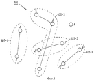
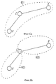
фиг. 6а - изображение пикосети, соответствующей одному из аспектов изобретения, в которой два беспроводных устройства, не находящиеся в зоне действия друг друга, осуществляют связь через промежуточное беспроводное устройство, которое находится в зоне действия каждого из остальных беспроводных устройств и которое действует в качестве ведущего устройства пикосети;
фиг.6b - иллюстрация альтернативного варианта осуществления изобретения, согласно которому два беспроводных устройства, не находящиеся в зоне действия друг друга, осуществляют связь через промежуточное беспроводное устройство, которое находится в зоне действия каждого из остальных беспроводных устройств и которое действует в качестве моста между двумя пикосетями;
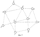
фиг. 7 - изображение примерной конфигурации, иллюстрирующей процедуру запроса, соответствующую одному из аспектов изобретения;
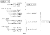
фиг. 8 - изображение расширенной процедуры запроса в соответствии с другим аспектом изобретения;
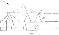
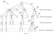
фиг. 9 - изображение дерева связности перового типа согласно одному из аспектов изобретения;
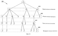
фиг.10 - изображение дерева связности второго типа согласно другому аспекту изобретения;
фиг.11 - иллюстрация использования дерева связности для определения возможных маршрутов для осуществления соединения, в соответствии с одним из аспектов изобретения;
фиг. 12 - блок-схема системы, реализующей различные признаки, соответствующие изобретению.Brief Description of the Drawings
The objectives and advantages of the invention are explained in the following detailed description, illustrated by drawings, which show the following:
figure 1 is a block diagram of a network having a star topology;
figure 2 is a block diagram of a network having a ring topology;
figure 3 is a block diagram of a network having a mesh topology;
FIG. 4 is an illustration of a wireless LAN having a diffuse topology in accordance with one aspect of the invention;
FIG. 5a is an image of a known local area network using one channel identical to the transmission medium;
FIG. 5b is an image of a known local area network in which a transmission medium is divided into several subchannels;
FIG. 5c is an image of a local area network that uses a multi-channel approach, in accordance with one aspect of the invention;
FIG. 6a is an image of a piconet in accordance with one aspect of the invention in which two wireless devices that are not in range of each other communicate through an intermediate wireless device that is in the range of each of the other wireless devices and which acts as the piconet master ;
Fig.6b is an illustration of an alternative embodiment of the invention, according to which two wireless devices that are not in range of each other communicate through an intermediate wireless device that is in the range of each of the other wireless devices and which acts as a bridge between two piconets ;
FIG. 7 is a view of an exemplary configuration illustrating a request procedure in accordance with one aspect of the invention;
FIG. 8 is a depiction of an extended request procedure in accordance with another aspect of the invention;
FIG. 9 is an image of a feather tree of connectivity according to one aspect of the invention;
figure 10 - image of a connected tree of the second type according to another aspect of the invention;
11 is an illustration of the use of a connectivity tree to determine possible routes for making a connection, in accordance with one aspect of the invention;
FIG. 12 is a block diagram of a system that implements various features consistent with the invention.
Детальное описание
Изобретение описывается ниже со ссылками на чертежи, на которых одинаковые элементы обозначены одинаковыми ссылочными позициями.Detailed description
The invention is described below with reference to the drawings, in which like elements are denoted by like reference numerals.
Как упомянуто при описании предшествующего уровня техники, традиционный одноканальный подход к локальным сетям характеризуется тем, что все устройства могут принимать всю информацию, передаваемую по каналу. Следовательно, сеть может иметь топологию типа звезды, как показано на фиг.1, кольца, как показано на фиг.2, или ячеистую топологию, как показано на фиг.3. В звездообразной топологии контроллер ведущего устройства, который планирует все передачи, может быть размещен в центре. В кольцевой и ячеистой топологиях применяется более распределенное управление. Для проводных локальных сетей в большей степени подходят звездообразная и кольцевая топологии, поскольку они минимизируют объем кабельных соединений. Однако ячеистая топология, при которой одно устройство может осуществлять связь со многими другими устройствами, автоматически возникает в локальных сетях радиосвязи вследствие всенаправленного характера распространения радиосигналов. При традиционных топологиях, показанных на фиг.1, 2 и 3 все устройства соединяются с каждым из остальных устройств в сети. Каждое устройство постоянно прослушивает передачи ведущего устройства или контролирует трафик в канале. Это предпочтительно для таких передач, как широковещательные передачи или многоадресные передачи. Однако такие применения используются лишь в течение малой доли времени. Напротив, в большинстве применений требуются услуги с использованием двухточечных соединений или соединений от одной точки к множеству точек между ограниченным количеством устройств, связанных с сетью. Для таких применений одноканальный подход означает ограничение эффективности. As mentioned in the description of the prior art, the traditional single-channel approach to local area networks is characterized in that all devices can receive all the information transmitted over the channel. Therefore, the network may have a star-type topology, as shown in FIG. 1, a ring, as shown in FIG. 2, or a mesh topology, as shown in FIG. 3. In a star topology, a master controller that schedules all transmissions can be centrally located. In ring and mesh topologies, more distributed control is applied. For wired LANs, star-shaped and ring topologies are more suitable, since they minimize the amount of cable connections. However, a mesh topology in which one device can communicate with many other devices automatically occurs in local radio networks due to the omnidirectional nature of the propagation of radio signals. With the traditional topologies shown in FIGS. 1, 2, and 3, all devices are connected to each of the other devices in the network. Each device is constantly listening to the transmission of the master device or monitors traffic in the channel. This is preferable for transmissions such as broadcasts or multicast transmissions. However, such applications are used only for a small fraction of the time. In contrast, most applications require point-to-point services or single-point to multiple-point services between a limited number of devices connected to a network. For such applications, a single channel approach means limited efficiency.
Поэтому в соответствии с одним из аспектов изобретения используется многоканальный подход, при котором устройства, которые желают осуществлять связь, не должны ожидать свободного места в канале, а вместо этого осуществляют поиск свободного канала, который они могут непосредственно использовать. При таком подходе все пользователи в среднем совместно используют все каналы в выделенном спектре частот, но только малое число пользователей используют конкретный канал в конкретный момент времени. Таким путем можно устанавливать одновременно действующие каналы связи без создания помех друг другу. Многоканальный подход также обеспечивает возможность повторного использования канала: если соединения в достаточной степени разнесены территориально, то они могут использовать один и тот же канал, не создавая значительных помех друг другу. Therefore, in accordance with one aspect of the invention, a multi-channel approach is used in which devices that wish to communicate do not have to wait for free space in the channel, but instead search for a free channel that they can directly use. With this approach, all users on average share all the channels in the selected frequency spectrum, but only a small number of users use a specific channel at a particular point in time. In this way, it is possible to establish simultaneously operating communication channels without interfering with each other. The multi-channel approach also provides the possibility of reusing the channel: if the connections are sufficiently geographically separated, then they can use the same channel without creating significant interference to each other.
В такой сети соединены только устройства, осуществляющие связь друг с другом. Вся сеть в целом состоит из рассеянных соединений или рассеянных субсетей (пикосетей) и поэтому определяется здесь как имеющая рассеянную топологию. Данная конфигурация отличается от существующих проводных локальных сетей и беспроводных локальных сетей тем, что хотя среда передачи (например, спектр частот шириной 83,5 МГц на частоте 2,4 ГГц) совместно используется всеми пользователями, однако информация, передаваемая в среде передачи, не используется совместно всеми пользователями. Вместо этого создаются каналы, и каждый канал совместно используется только конкретными участниками, а именно теми, которые должны совместно использовать передаваемую информацию. Хотя каждое устройство потенциально может соединяться с каждым другим устройством в пределах его зоны действия, оно не будет одновременно соединяться со всеми такими устройствами в его зоне действия. Можно устанавливать множество произвольных соединений, каждое из которых работает независимо. In such a network, only devices communicating with each other are connected. The entire network as a whole consists of scattered connections or scattered subnets (piconets) and is therefore defined here as having a scattered topology. This configuration differs from existing wired local area networks and wireless local area networks in that although the transmission medium (for example, the frequency spectrum with a width of 83.5 MHz at a frequency of 2.4 GHz) is shared by all users, however, the information transmitted in the transmission medium is not used shared by all users. Instead, channels are created, and each channel is shared only by specific participants, namely those who must share the transmitted information. Although each device can potentially connect to every other device within its coverage area, it will not simultaneously connect to all such devices in its coverage area. You can establish many arbitrary connections, each of which works independently.
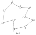
Пример рассеянной сети 401, соответствующей изобретению, показан на фиг. 4. На этом чертеже показаны четыре субсети 403-1,..., 403-4. В каждой субсети 403-х принимают участие только те устройства, которые на самом деле желают обмениваться информацией. Каждая субсеть 403-х имеет свой собственный виртуальный канал, и только участники пикосети соревнуются за получение соответствующего канала. Субсети 403-х функционируют независимо по отношению друг к другу. Устройства, для которых нет необходимости в информационном обмене (например, устройство 8 на фиг.4), не устанавливают соединения. Однако эти устройства периодически сканируют спектр на наличие пейджинговых сообщений, чтобы установить наличие другого устройства, которое желает установить с ним связь. An example of a diffuse
Для исключения взаимных помех между различными соединениями и субсетями 403-х применяется некоторая форма адаптивного распределения каналов или некоторая форма расширения спектра. Если применяется адаптивное распределение каналов, то устройства, желающие установить соединения, выполняют измерения в различных каналах и затем выбирают наилучший канал (т.е. канал с наименьшими помехами). Адаптивная схема имеет, однако, некоторые недостатки по сравнению с методами расширениями спектра, описанными ниже. Во-первых, может оказаться затруднительным получить надежные измерения в канале вследствие импульсного характера трафика данных. Во-вторых, должен использоваться некоторый механизм, обеспечивающий устройствам, желающим установить связь друг с другом, возможность выбора одного и того же наилучшего канала, что является нетривиальной задачей. Неизбежно использование центрального контроллера. В противоположность этому, расширение спектра, также требуемое Федеральной Комиссией по коммуникациям (FCC) в нелицензируемой полосе частот, подобной ISM-диапазону на частоте 2,4 ГГц, характеризует собой более привлекательный для использования метод. To eliminate mutual interference between different connections and subnets of the 403s, some form of adaptive channel allocation or some form of spreading is applied. If adaptive channel allocation is used, then devices wishing to establish connections take measurements on different channels and then select the best channel (i.e., the channel with the least interference). The adaptive scheme, however, has some drawbacks compared to the spread spectrum methods described below. First, it may be difficult to obtain reliable measurements in the channel due to the pulsed nature of the data traffic. Secondly, some mechanism should be used to provide devices wishing to communicate with each other, the ability to select the same best channel, which is a non-trivial task. Inevitably using a central controller. In contrast, the expansion of the spectrum, also required by the Federal Communications Commission (FCC) in an unlicensed frequency band similar to the ISM band at 2.4 GHz, is a more attractive method to use.
В случае, когда используется метод расширения спектра, для растягивания спектра взаимных помех может применяться расширение спектра частот путем прямой модуляции последовательностью или скачкообразного изменения частоты. Соответствующий эфирный интерфейс, использующий медленное скачкообразное изменение частоты (СИЧ) описан в заявке на патент США 08/685069 на "Систему радиосвязи малой дальности действия и способ ее использования", поданной 23 июля 1996 на имя Paul W.Dent и Jacobus C.Haartsen, переуступленной заявителю настоящей заявки. В указанной заявке описан эфирный интерфейс, который обеспечивает устойчивость по отношению к взаимным помехам от находящихся рядом пользователей, а также к другим источникам помех путем применения режима скачкообразного изменения частоты и схемы быстрой повторной передачи пакетов. In the case where the spread spectrum method is used, to expand the spectrum of mutual interference, the spread of the frequency spectrum can be applied by direct modulation by a sequence or by frequency hopping. The corresponding air interface using slow frequency hopping (SICH) is described in US Patent Application 08/685069 for "Short Range Radio Communication System and Method of Its Use", filed July 23, 1996 addressed to Paul W. Dent and Jacobus C. Haartsen, assigned to the applicant of this application. The said application describes an air interface that provides immunity to interference from nearby users, as well as to other sources of interference by applying a frequency hopping mode and fast packet retransmission scheme.
Скачкообразное изменение частоты по сравнению с расширением спектра за счет прямой модуляции последовательностью является предпочтительным по целому ряду причин. Во-первых, желательно иметь возможность устанавливать множество находящихся в непосредственной близости, но некоординированных соединений. В такой среде расширение спектра за счет прямой модуляции последовательностью создало бы ряд проблем, связанных со степенью удаленности. Механизм управления мощностью не может быть реализован из-за некоординированности передатчиков. Наличие неизвестных источников помех также потребовало бы необходимости в относительно высоком выигрыше за счет обработки и высокой передаваемой мощности. Высокий коэффициент расширения спектра, который связан с получением высокого выигрыша при обработке, привел бы к удорожанию приемопередатчика. Что касается высокой передаваемой мощности, то это представляется нежелательным в условиях аппаратуры с батарейным питанием. Наконец, наилучшая устойчивость по отношению к взаимным помехам достигается путем использования всего располагаемого спектра, т.е. полосы 83,5 МГц на частоте 2,4 ГГц. Расширение спектра за счет прямой модуляции последовательностью может использовать только часть спектра ввиду ограничений по ширине полосы в приемопередатчике. В противоположность этому, системы со скачкообразным изменением частоты могут осуществлять перестройку частоты в среднем во всем спектре, но при этом иметь приемлемое мгновенное значение ширины полосы канала. Аналогично стандарту IEEE 802.11, настоящее изобретение предусматривает использование 79 скачков с шириной полосы 1 МГц. Виртуальный канал определен как псевдослучайная последовательность скачков, изменяющаяся в среднем по всем 79 значениям. Различные соединения могут устанавливаться одновременно путем применения различных виртуальных каналов. Случайным образом различные виртуальные каналы могут использовать одно и то же значение скачкообразно изменяющейся частоты, и в этом случае возникнет конфликт. Для исключения искажений в этом случае используется исправление ошибок и избыточность. An abrupt change in frequency compared to spectrum spreading due to direct modulation by a sequence is preferred for a number of reasons. First, it is desirable to be able to establish many in the immediate vicinity, but uncoordinated connections. In such an environment, spectrum expansion due to direct modulation by a sequence would create a number of problems related to the degree of remoteness. The power control mechanism cannot be implemented due to uncoordinated transmitters. The presence of unknown sources of interference would also require a relatively high gain due to processing and high transmitted power. A high spreading factor, which is associated with a high gain in processing, would lead to an increase in the cost of the transceiver. As for the high transmitted power, this seems undesirable in the conditions of equipment with battery power. Finally, the best stability with respect to mutual interference is achieved by using the entire available spectrum, i.e. 83.5 MHz bands at 2.4 GHz. Spectrum expansion due to direct modulation by a sequence can only use part of the spectrum due to bandwidth limitations in the transceiver. In contrast, systems with frequency hopping can perform frequency tuning on average throughout the spectrum, but still have an acceptable instantaneous channel bandwidth. Similar to the IEEE 802.11 standard, the present invention provides for the use of 79 hops with a bandwidth of 1 MHz. A virtual channel is defined as a pseudo-random sequence of jumps that varies on average for all 79 values. Different connections can be established simultaneously by using different virtual channels. Randomly, different virtual channels can use the same value of an abruptly changing frequency, in which case a conflict will arise. In this case, error correction and redundancy are used to eliminate distortion.
Совместное использование среды передачи в соответствии с настоящим изобретением по сравнению с другими системами поясняется далее со ссылками на фиг. 5а, 5b и 5с. Фиг.5а иллюстрирует известный одноканальный метод, при котором имеется только один канал 503, и этот канал 503 идентичен среде передачи 501, как это имеет место в проводных локальных сетях. Все пользователи конкурируют за получение одного и того же канала 503, и для обеспечения каждому пользователю возможности получить часть ресурсов передачи, используется мультиплексирование путем временного разделения каналов. Доступ к каналу 503 контролируется либо централизованно, либо распределенным образом. Фиг.5b иллюстрирует известную систему, в которой среда передачи 501 разделена на несколько субканалов 505-х, например, с использованием мультиплексирования путем частотного разделения каналов. Пользователи в пределах дальности действия устанавливают сеть с использованием одного из субканалов 505-х. Эти субканалы 505-х являются либо фиксированными (подобно тому, как в стандарте HIPERLAN) или осуществляют медленное скачкообразное изменение частоты в пределах всей среды передачи (подобно тому, как реализовано расширение спектра путем медленного скачкообразного изменения частоты согласно стандарту IEEE 802.11). Т.е. в различные моменты времени выбирается отличающийся субканал 505-х. Однако в любой момент времени все пользователи конкурируют за получение доступа к одному и тому же субканалу. Например, на фиг. 5b иллюстрируется момент времени, в который каждый из пользователей 1-9 конкурирует за получение доступа к субканалу 505-3. Sharing of a transmission medium in accordance with the present invention compared to other systems is explained below with reference to FIG. 5a, 5b and 5c. Fig. 5a illustrates a known single-channel method in which there is only one
Фиг. 5с иллюстрирует многоканальный подход, соответствующий изобретению. Вновь среда передачи 501 разделена на субканалы. Однако группа соединенных пользователей 507-х мультиплексируется (например, путем скачкообразного изменения частоты) во всех субканалах 509-х с относительно высокой частотой. Пакеты мультиплексируются с частотой скачков среди различных субканалов 509-х. Закон скачкообразного изменения представляет виртуальный канал. На фиг. 5с представлены три группы 507-х пользователей: первая группа 507-1 включает пользователей, идентифицированных как пользователи 2, 3 и 4; вторая группа 507-2 включает пользователей, идентифицированных как пользователи 6, 7 и 9. В соответствии с изобретением каждая из этих групп 507-х образует пикосеть. В данном примере дополнительный пользователь, т.е. пользователь 1 не включен ни в одну из групп 507-х пользователей и поэтому не соединен ни с одной из этих трех пикосетей. FIG. 5c illustrates the multi-channel approach of the invention. Again,
Ясно, что многоканальный подход, иллюстрируемый с помощью фиг.5с, обеспечивает намного более высокую общую пропускную способность, чем одноканальный подход, иллюстрируемый с помощью фиг.5b, когда среда передачи должна подразделяться на множество меньших субканалов, вследствие ограничений в приемопередатчиках радиосвязи или нормативных ограничений. В настоящем изобретении каждая пикосеть соответствует виртуальному каналу, использующему конкретную последовательность для мультиплексирования (путем скачкообразного изменения) субканалов и использующему конкретный адрес линии связи для идентификации своих пакетов. Различные пикосети повторно используют все субканалы случайным образом; каждый субканал используется в среднем всеми пикосетями. Совместное использование субканалов приводит в результате к статистическому мультиплексированию между пикосетями, что обеспечивает повышение эффективности в условиях импульсного трафика, имеющего место в приложениях, связанных с передачей данных. Ввиду высокой частоты скачков (один пакет на скачок) статистическое мультиплексирование имеет намного более высокую эффективность, чем, например, достигаемая в рядом расположенных беспроводных локальных сетях, использующих расширение спектра за счет медленного скачкообразного изменения частоты согласно стандарту 802.11, при котором время пребывания в одном канале намного более длительное. It is clear that the multi-channel approach illustrated by FIG. 5c provides a much higher overall throughput than the single-channel approach illustrated by FIG. 5b, when the transmission medium must be subdivided into many smaller subchannels, due to limitations in radio transceivers or regulatory restrictions . In the present invention, each piconet corresponds to a virtual channel using a specific sequence for multiplexing (by hopping) subchannels and using a specific link address to identify its packets. Different piconets reuse all subchannels at random; each subchannel is used on average by all piconets. The joint use of subchannels results in statistical multiplexing between piconets, which provides increased efficiency in the conditions of impulse traffic, which occurs in applications related to data transmission. Due to the high frequency of jumps (one packet per jump), statistical multiplexing has much higher efficiency than, for example, achieved in adjacent wireless local area networks that use spectrum spreading due to slow frequency hopping according to the 802.11 standard, in which the time spent in one channel much longer.
Тип услуги, обеспечиваемой при многоканальном подходе, может быть охарактеризован как занимающий промежуточное положение между услугой с чистой коммутацией каналов и услугой с чистой коммутацией пакетов. Виртуальные каналы определены подобно каналам в ориентированных на соединение сетях с коммутацией пакетов. Однако каждый виртуальный канал уникальным образом связан с двумя или более пользователей и работает синхронным образом, подобно каналам в сетях с коммутацией каналов. Кроме того, в отличие от субканалов или каналов в сетях с коммутацией каналов, которые используются исключительно соединенными пользователями, каналы в пикосетях совместно используются в среднем всеми пользователями. Для применений с импульсным характером данных это обеспечивает более высокую пропускную способность и лучшее использование среды передачи вследствие статистического мультиплексирования пакетов, что не встречается в традиционных сетях с коммутацией каналов. The type of service provided by the multi-channel approach can be characterized as taking an intermediate position between the service with pure circuit switching and the service with pure packet switching. Virtual channels are defined similarly to channels in packet-oriented connection-oriented networks. However, each virtual channel is uniquely associated with two or more users and operates in a synchronous manner, similar to channels in circuit-switched networks. In addition, unlike subchannels or channels in circuit-switched networks that are used exclusively by connected users, piconet channels are shared on average by all users. For applications with a pulsed data nature, this provides higher bandwidth and better utilization of the transmission medium due to statistical packet multiplexing, which is not found in traditional circuit-switched networks.
Обсуждение далее будет фокусироваться на примерах способов, позволяющих устройствам устанавливать соединения произвольной пикосети, описанные выше. Описанная здесь система была оптимизирована для быстрой установки и завершения произвольных соединений между произвольными беспроводными устройствами, рассредоточенными в ограниченной области. Могут устанавливаться двухточечные соединения и соединения от одной точки к множеству точек. Все устройства являются одноранговыми устройствами, каждое из которых использует идентичную радиоприемную аппаратуру связи. В соответствии с одним из аспектов изобретения одному устройству временно придается функция ведущего устройства, когда инициируется установление соединения. Такое назначение продолжается только в течение длительности соединения. Если только не переопределено, ведущим устройством является устройство, которое инициировало соединение. Каждое устройство имеет уникальный адрес или код доступа, с помощью которого оно идентифицируется. В возможном варианте осуществления адрес имеет длительность 64 бита, но, разумеется, это не является обязательным для каждого варианта осуществления. Адрес определяет псевдослучайную последовательность скачкообразного изменения или виртуальный канал, который использует устройство, когда оно является ведущим устройством. Ведущее устройство, таким образом, должно распределять свой адрес среди подчиненных так, чтобы все они использовали тот же самый виртуальный канал со скачкообразным изменением. В течение длительности соединения используется очень длинная последовательность скачков, в которой каждый скачок из 79 возможных скачков реализуется с равной вероятностью. Фаза последовательности скачков определяется системным тактовым сигналом в приемопередатчике ведущего устройства. The discussion will further focus on examples of methods that allow devices to establish arbitrary piconet connections described above. The system described here has been optimized for the quick setup and completion of arbitrary connections between arbitrary wireless devices dispersed in a limited area. Point-to-point connections and connections from one point to many points can be established. All devices are peer-to-peer devices, each of which uses the same radio communication equipment. In accordance with one aspect of the invention, one device is temporarily given the function of a master when a connection is initiated. Such an appointment only lasts for the duration of the connection. Unless overridden, the master is the device that initiated the connection. Each device has a unique address or access code with which it is identified. In a possible embodiment, the address is 64 bits long, but, of course, this is not necessary for each embodiment. The address defines the pseudo-random hop sequence or virtual channel that the device uses when it is the master. The master, therefore, must distribute its address among subordinates so that they all use the same virtual channel with a hopping change. Over the duration of the connection, a very long sequence of jumps is used, in which each jump out of 79 possible jumps is realized with equal probability. The phase of the jump sequence is determined by the system clock in the transceiver of the master.
Устройство, находящееся в дежурном режиме, активизируется с регулярными временными интервалами, например, каждые Т секунд (например, 1,28 с) для прослушивания пейджинговых сообщений, которые состоят из его адреса. Такое пейджинговое сообщение может рассматриваться как код последовательности прямой модуляции из 64 кодовых элементов: приемник осуществляет корреляционную обработку по отношению к этому коду и активизирует остальную часть блоков приемопередатчика только в том случае, если результат корреляции превышает определенный порог. С каждым новым моментом активизации устройство активизируется при новом значении скачка в соответствии с последовательностью активизации, состоящей из 32 скачков. Эти 32 скачка активизации являются уникальными и равномерно распределены в ISM-диапазоне на частоте 2,4 ГГц. Как скачки активизации, так и псевдослучайная последовательность скачков активизации определяются посредством адреса устройства, находящегося в дежурном режиме. Фаза последовательности определяется системным тактовым сигналом устройства, находящегося в дежурном режиме. Устройство, пытающееся установить соединение (устройство, посылающее пейджинговый вызов), повторно передает пейджинговое сообщение (которое является кодом расширения, представляющим адрес приемника вызова) с высокой частотой повторения на различных значениях скачков. Оно использует скачки активизации и последовательность скачков активизации приемника вызова и пытается соединиться с приемником вызова путем передачи пейджингового сообщения на возможно большем количестве значений скачков в последовательности скачков активизации. Имея оценку системного тактового сигнала приемника вызова, вызывающее устройство может осуществить начальную синхронизацию, поскольку оно знает, когда и на каком значении скачка приемник вызова будет активизирован. При условии известности тактового сигнала приемника вызова задержка начальной синхронизации для наихудшего случая равна Т (вследствие того, что устройство, находящееся в дежурном режиме, активизируется только каждые Т секунд). В случае неизвестности тактового сигнала приемника вызова задержка начальной синхронизации для наихудшего случая равна 2Т. Эти задержки получены в среде передачи без учета ошибок. При наличии ошибок время начальной синхронизации может увеличиться. Вышеописанные способы установления связи с устройством, находящимся в дежурном режиме более полно описаны в заявке на патент США 08/771692 на "Способ доступа в системе связи со скачкообразным изменением частоты", поданной 23 декабря 1996 на имя Haartsen et al. A device in standby mode is activated at regular time intervals, for example, every T seconds (for example, 1.28 s) to listen to paging messages that consist of its address. Such a paging message can be considered as a direct modulation sequence code of 64 code elements: the receiver performs correlation processing with respect to this code and activates the rest of the transceiver blocks only if the correlation result exceeds a certain threshold. With each new moment of activation, the device activates with a new jump value in accordance with the activation sequence consisting of 32 jumps. These 32 activation jumps are unique and evenly distributed in the ISM band at 2.4 GHz. Both the activation jumps and the pseudo-random sequence of activation jumps are determined by the address of the device in standby mode. The phase of the sequence is determined by the system clock signal of the device in standby mode. A device attempting to establish a connection (a device sending a paging call) retransmits a paging message (which is an extension code representing the address of the call receiver) with a high repetition rate at various hop values. It uses activation jumps and a sequence of jumps of activation of the call receiver and tries to connect to the call receiver by sending a paging message on as many jump values as possible in the sequence of activation jumps. Having an estimate of the system clock of the call receiver, the calling device can perform initial synchronization, because it knows when and at what jump value the call receiver will be activated. If the clock signal of the call receiver is known, the initial synchronization delay for the worst case is T (due to the fact that the device in standby mode is activated only every T seconds). If the call receiver clock is not known, the initial synchronization delay for the worst case is 2T. These delays are received in the transmission medium without error. If there are errors, the initial synchronization time may increase. The above methods for communicating with a standby device are more fully described in US Patent Application 08/771692 on “An Access Method in a Frequency Hopping Communication System”, filed December 23, 1996 to Haartsen et al.
После того как соединение установлено, устройство, посылающее пейджинговое сообщение, которое обозначено как ведущее устройство, пересылает свой адрес и свой системный тактовый сигнал к приемнику вызова. Код и тактовый сигнал ведущего устройства затем будут использоваться для определения виртуального канала со скачкообразным изменением частоты. Этот код ведущего устройства также используется для идентификации пакетов в виртуальном канале. Т. е. каждому пакету в виртуальном канале, независимо от то того, какой пользователь виртуального канала является передающим, предшествует адрес ведущего устройства, служащий в качестве адреса линии связи. Если различные устройства в одной и той же области устанавливают различные соединения, то каждое из них использует различный виртуальный канал и различный адрес линии связи, как это определено параметрами устройств, которые инициировали соединения (т.е. ведущих устройств). After the connection is established, the device sending the paging message, which is designated as the master device, forwards its address and its system clock to the call receiver. The master code and clock will then be used to identify the virtual channel with frequency hopping. This master code is also used to identify packets on the virtual channel. That is, each packet in the virtual channel, regardless of which user of the virtual channel is transmitting, is preceded by the address of the master device serving as the address of the communication line. If different devices in the same area establish different connections, then each of them uses a different virtual channel and a different communication line address, as determined by the parameters of the devices that initiated the connections (i.e., the master devices).
Для того чтобы позволить более чем двум пользователям принимать участие в работе пикосети, ограниченные возможности установления соединений типа от одной точки к множеству точек определены в возможном варианте осуществления, что позволяет устройству, назначенному для выполнения функций ведущего устройства, осуществлять соединения с множеством подчиненных устройств. В результате возникает звездообразная топология с ведущим устройством в центре. Подчиненные устройства не могут осуществлять связь непосредственно одно с другим, а должны использовать ведущее устройство в качестве посредника. Используется схема опроса, которая организует передачи различных подчиненных устройств. Все подчиненные устройства синхронизированы по времени, т.е. все они прослушивают ведущее устройство в одно и то же время. Только то подчиненное устройство, которое адресовано (опрашивается для ответа) в выделенном временном интервале приема подчиненного устройства, имеет возможность ответа в последующем выделенном временном интервале передачи подчиненного устройства. Все устройства, ведущее и подчиненные, распознают пакеты в виртуальном канале по коду линии связи (который представляет собой адрес ведущего устройства). Конкретное подчиненное устройство в пикосети идентифицируется адресом ее участника. В возможном варианте осуществления адрес участника представляет собой 3-битовый адрес в заголовке пакета. -битовый адрес ограничивает число участников в пикосети до восьми. Если конкретный вариант осуществления не позволяет расширить заголовок пакета для включения более широкого адресного поля, то большее количество участников может быть обеспечено путем реализации дополнительной схемы адресации в полезной нагрузке пакета. In order to allow more than two users to participate in the piconet, the limited possibilities for establishing connections from one point to many points are defined in a possible embodiment, which allows the device assigned to perform the functions of the master device to make connections with many slaves. The result is a star-shaped topology with a master device in the center. Slaves cannot communicate directly with one another, but must use the master as an intermediary. A polling scheme is used that organizes transfers of various slaves. All slaves are time synchronized, i.e. they all listen on the master at the same time. Only the slave device that is addressed (interrogated for a response) in the allocated time slot for receiving the slave device can respond in the subsequent allocated time slot for transmitting the slave device. All devices, the master and slaves, recognize packets in the virtual channel by the code of the communication line (which is the address of the master). A particular slave device in the piconet is identified by the address of its member. In a possible embodiment, the member address is a 3-bit address in the packet header. The bit address limits the number of participants in the piconet to eight. If a particular embodiment does not allow expanding the packet header to include a wider address field, then more participants can be achieved by implementing an additional addressing scheme in the packet payload.
Линия связи между устройствами использует дуплексную схему с разделением по времени, согласно которой приемопередатчик радиосвязи попеременно осуществляет передачу и прием. Кадр дуплексного режима с временным разделением состоит из выделенных временных интервалов передачи и приема. Сообщения, подлежащие передаче, разделяются на пакеты. Каждый временной интервал передачи и приема может содержать максимум один пакет передачи и один пакет приема соответственно. Последовательные временные интервалы используют различные значения скачкообразного изменения, как определено виртуальным каналом. Виртуальный канал обеспечивает синхронную линию связи: устройства, которые совместно используют один и тот же виртуальный канал скачкообразно перестраиваются по частоте синхронно и в строгом соответствии с хронированием дуплексного режима с временным разделением. Однако временной интервал не обязательно должен быть занят. Если отсутствуют данные, которые должны передаваться, то два соединенных устройства могут скачкообразно перестраиваться синхронно без обмена пакетами. Хотя услуга, обеспечиваемая такой линией связи, по своей природе является ориентированной на соединение, каждый пакет содержит адрес линии связи, соответствующий виртуальному каналу. Канал не является свободным от конкуренции. Различные виртуальные каналы могут случайным образом использовать одно и то же значение скачкообразного изменения. Следовательно, приемник вызова должен анализировать принятый адрес линии связи, чтобы идентифицировать, действительно ли принятый пакет предназначен для него, или пакет связан с другим виртуальным каналом, который случайно пришелся на то же самое значение скачкообразного изменения, что и в виртуальном канале приемника вызова. Использование адреса линии связи является достаточно важным вследствие того, что импульсный характер трафика может привести к пустым временным интервалам, которые случайным образом могут оказаться заполненными другими линиями связи, и вследствие того, что могут иметь место ситуации с ближним/дальним местонахождением, при которых мешающий пакет полностью вытесняет полезный пакет. The communication line between the devices uses a time division duplexed circuit according to which the radio transceiver alternately transmits and receives. A time division duplex frame consists of allocated transmission and reception time slots. Messages to be transmitted are packetized. Each transmission and reception time interval may contain a maximum of one transmission packet and one reception packet, respectively. Successive time slots use different hop values as determined by the virtual channel. A virtual channel provides a synchronous communication line: devices that share the same virtual channel are frequency-hopped synchronously and in strict accordance with time division duplex timing. However, the time interval does not have to be busy. If there is no data to be transmitted, then the two connected devices can hop-hop in sync without packet exchange. Although the service provided by such a communication line is inherently connection oriented, each packet contains a communication line address corresponding to a virtual channel. The channel is not free from competition. Different virtual channels can randomly use the same hop value. Therefore, the call receiver must analyze the received address of the communication line to identify whether the received packet is really intended for it, or the packet is connected to another virtual channel, which accidentally fell on the same value of the hopping, as in the virtual channel of the call receiver. The use of the communication line address is quite important due to the fact that the pulsed nature of the traffic can lead to empty time intervals, which may randomly be filled with other communication lines, and due to the fact that there may be situations with near / far location, in which an interfering packet completely supersedes the useful package.
Передача речи не представляет проблем в данной системе ввиду того, что обеспечена синхронная линия связи. Если речь является частью информационного потока, то речевой пакет будет передаваться в каждом кадре дуплексного режима с временным разделением. Случайные конфликтные ситуации могут преодолеваться с использованием методов восстановления в приемнике вызова или они могут игнорироваться. Последний подход требует применения более помехоустойчивых методов кодирования речи, подобно непрерывной дельта-модуляции с переменной крутизной. Voice transmission is not a problem in this system due to the fact that a synchronous communication line is provided. If speech is part of the information flow, then the speech packet will be transmitted in each time division duplex frame. Accidental conflict situations can be overcome using recovery methods in the call receiver, or they can be ignored. The latter approach requires the use of more noise-resistant speech coding methods, like continuous delta modulation with variable slope.
Применяется схема запроса автоматической повторной передачи (ЗАПП), при которой об успешной или безуспешной передаче пакета в кадре дуплексного режима с временным разделением (ДВР) информируют непосредственно в следующем кадре ДВР. Таким путем по протоколу ЗАПП затрачивается минимальный спектр: повторно передаются только безуспешно переданные пакеты. Кроме того, минимизированы ожидание и перегрузка (в рассматриваемом примере осуществления схема ЗАПП требует только двух битов в заголовке пакета). Реализация схемы ЗАПП может быть осуществлена непосредственно аппаратными средствами и предпочтительно сосредоточено очень близко к физическому уровню в протоколе связи. An automatic retransmission request (ZAP) scheme is applied in which a successful or unsuccessful transmission of a packet in a time division duplex (DMA) frame is reported directly in the next DDA frame. In this way, according to the ZAPP protocol, a minimal spectrum is expended: only packets that were transmitted unsuccessfully are retransmitted. In addition, the wait and congestion are minimized (in this example, the implementation of the ZAPP scheme requires only two bits in the packet header). The implementation of the ZAPP scheme can be carried out directly by hardware and is preferably concentrated very close to the physical layer in the communication protocol.
Звездообразная топология и схема опроса для доступа, соответствующие настоящему изобретению, являются следствием определения пикосети и жесткой временной синхронизации в виртуальном канале. Если два подчиненных устройства должны осуществлять связь непосредственно одно с другим, то создается дополнительная сеть, над которой исходное ведущее устройство не имеет непосредственного контроля. Одно из подчиненных устройств смещает свою кадровую синхронизацию (ДВР) на половину кадра. Это подчиненное устройство не может больше прослушивать ведущее устройство (оно действует в качестве ведущего устройства в новой пикосети), и первоначальное ведущее устройство не может прослушивать подчиненное устройство. Хотя для пикосети используется единственный (виртуальный) канал, распределенный контроль не возможен вследствие применяемой жесткой временной синхронизации. The star topology and polling scheme for access in accordance with the present invention are a consequence of the determination of the piconet and the tight time synchronization in the virtual channel. If two slaves must communicate directly with one another, an additional network is created over which the original master does not have direct control. One of the slaves shifts its frame synchronization (DDA) by half the frame. This slave can no longer listen to the master (it acts as the master in the new piconet), and the original master cannot listen to the slave. Although a single (virtual) channel is used for a piconet, distributed control is not possible due to the applied tight time synchronization.
Для получения возможности соединения с устройством, важно знать его адрес. В обычных локальных сетях (включая традиционные беспроводные локальные сети) эти адреса обычно известны всем участникам локальной сети. Поскольку все устройства уже соединены друг с другом, устройства могут просто устанавливать линии связи с использованием надлежащих адресов при передаче сообщения. Нет необходимости устанавливать соединение. Устройство, которое распознает свой адрес, просто принимает сообщение, в то время как все другие устройства игнорируют его. To be able to connect to the device, it is important to know its address. In ordinary local area networks (including traditional wireless local area networks), these addresses are usually known to all participants in the local network. Since all devices are already connected to each other, devices can simply establish communication lines using the appropriate addresses when transmitting a message. No need to establish a connection. A device that recognizes its address simply receives the message, while all other devices ignore it.
Поскольку рассредоточенная сеть устанавливается на произвольной основе, устройства не знают заранее все адреса соседних устройств. Для решения этой проблемы и в соответствии с другим аспектом изобретения предусматривается процедура запроса, которая позволяет устройствам получить адреса ближних устройств. Процедура запроса весьма сходна с процедурой направления поискового вызова. Вместо пейджингового сообщения передается сообщение запроса с высокой частотой повторения на различных значениях скачкообразного изменения. В примере осуществления сообщение запроса представляет собой 64-битовый код, предписывающий приемнику вызова сообщить о своих параметрах устройства. Подобно адресу, код запроса определяет, например, 32 различных значения скачкообразного изменения для запроса и последовательность скачкообразного изменения для запроса. Устройства, которые принимают сообщение запроса, передают в ответ одиночный пакет, включающий адрес приемника вызова, системный тактовый сигнал приемника вызова и его класс обслуживания (например, является ли устройство принтером, дорожным компьютером, базовой станцией и т.п. ). Устройства могут случайным образом выбирать ответное значение скачкообразного изменения в последовательности скачкообразного изменения для запроса, чтобы избежать конфликтных ситуаций. Запрашивающее устройство собирает все отклики и формирует список кодов и смещений тактовых сигналов для устройств, которые находятся в пределах дальности действия. Эта информация может затем использоваться, если желательно установление соединения. Поскольку устройства являются подвижными, процедура запроса может повторяться периодически, так чтобы список мог обновляться по мере необходимости. Since a distributed network is installed on an arbitrary basis, devices do not know in advance all the addresses of neighboring devices. To solve this problem and in accordance with another aspect of the invention, a request procedure is provided that allows devices to obtain addresses of nearby devices. The request procedure is very similar to the procedure for sending a search call. Instead of a paging message, a request message is transmitted with a high repetition rate at various hop values. In an embodiment, the request message is a 64-bit code instructing the call receiver to report its device parameters. Like the address, the request code determines, for example, 32 different hop values for the request and a hop sequence for the request. Devices that receive a request message send back a single packet, including the address of the call receiver, the system clock of the call receiver and its class of service (for example, whether the device is a printer, travel computer, base station, etc.). Devices can randomly select the hopping response value in the hopping sequence for the request in order to avoid conflict situations. The requesting device collects all responses and generates a list of codes and clock offsets for devices that are within range. This information can then be used if a connection is desired. Since the devices are mobile, the request procedure can be repeated periodically so that the list can be updated as needed.
Вышеописанная процедура позволяет устройству собрать всю информацию, необходимую ему для установления пикосети с устройствами, которые находятся в пределах дальности действия. Однако в некоторых случаях устройству может потребоваться установить соединение с устройством, находящимся за пределами дальности действия (т.е. слишком удалено для осуществления прямой радиосвязи между устройствами). В соответствии с другим аспектом изобретения эта проблема решается с использованием промежуточного устройства, которое находится в пределах дальности действия как устройства-источника, так и устройства-адресата. В возможном варианте осуществления промежуточное устройство действует как ведущее устройство в конфигурации соединения от точки к множеству точек и ретранслирует информацию между двумя устройствами, которые не имеют возможности непосредственного соединения. Данный вариант осуществления приведен на фиг.6а, на которой представлены устройства А и В, находящиеся за пределами дальности действия. Третье устройство С находится в пределах дальности действия обоих устройств А и В и используется в качестве ведущего устройства. Устройства А и В являются подчиненными устройствами в этой одиночной пикосети 601. The above procedure allows the device to collect all the information it needs to establish a piconet with devices that are within range. However, in some cases, the device may need to establish a connection with a device that is out of range (i.e. too far away for direct radio communication between the devices). In accordance with another aspect of the invention, this problem is solved using an intermediate device that is within the range of both the source device and the destination device. In a possible embodiment, the intermediate device acts as a master in a point-to-multiple-point connection configuration and relays information between two devices that do not have direct connectivity. This embodiment is shown in FIG. 6 a, which shows devices A and B that are outside the range. The third device C is within the range of both devices A and B and is used as a master device. Devices A and B are slaves in this
В альтернативном варианте, показанном на фиг.6b, промежуточное устройство, находящееся в пределах дальности действия двух других устройств, действует как мост между устройством-источником и устройством-адресатом. Мост представляет собой более сложное устройство, имеющее возможность соединения с двумя пикосетями. Как показано на фиг.6b, устройства А и В, которые находятся за пределами дальности действия относительно друг друга, принимают участие в различных пикосетях 603 и 605. Мост С принимает участие в каждой из пикосетей 603 и 605. Так как две пикосети 603 и 605 некоординированы, мост С по существу содержит два приемопередающих устройства, каждое из которых принимает участие в различной одной из сетей 603 и 605. Внутри моста С информация передается вперед и назад между двумя приемопередатчиками. Так как мост С использует два виртуальных канала (две пикосети) вместо одной, он обеспечивает более высокую пропускную способность между устройствами А и В, чем пропускная способность конфигурации соединения от точки к множеству точек по фиг.6а. In the alternative embodiment shown in FIG. 6b, an intermediate device within the range of two other devices acts as a bridge between the source device and the destination device. A bridge is a more complex device that can be connected to two piconets. As shown in FIG. 6b, devices A and B that are out of range of each other participate in
Для обеспечения установления мостовой конфигурации в системе необходим более сложный процесс запроса для обеспечения возможности каждому устройству определить адреса не только тех устройств, которые находятся в пределах дальности действия, но и адреса тех устройств вне дальности действия, которые находятся в пределах дальности действия доступных устройств-мостов. Этот более сложный процесс запроса описан ниже более детально. Для данного изложения отмечается лишь, что если необходимо установить соединение с устройством, которое находится вне дальности действия, устройство-источник сначала устанавливает соединение с ведущим устройством или устройством-мостом, которое находится в пределах дальности действия устройства-источника. Как только соединение установлено, устройство-источник выдает команду ведущему устройству или устройству-мосту устанавливать последующее соединение со следующим мостом или с конечным адресатом. Как только ведущее устройство или устройство-мост установит два соединения, оно просто ретранслирует всю приходящую информацию пользователей. Информация управления, однако, обрабатывается отдельным образом. To ensure the establishment of a bridge configuration in the system, a more complex query process is required to ensure that each device can determine not only the addresses of devices that are within range, but also the addresses of those devices that are outside the range of which are within the range of available bridge devices . This more complex request process is described in more detail below. For this presentation, it is only noted that if it is necessary to establish a connection with a device that is out of range, the source device first establishes a connection with the master device or bridge device that is within the range of the source device. Once the connection is established, the source device instructs the master or bridge device to establish a subsequent connection to the next bridge or to the final destination. As soon as the master or bridge device establishes two connections, it simply relays all incoming user information. Management information, however, is handled separately.
Использование промежуточных устройств для установления соединений зависит, разумеется, от расстояний на местности и дальности действия отдельного устройства. Дальность радиосвязи устройства может быть ограничена, поскольку это связано с экономичной и эффективной реализацией и с низким потреблением питающей мощности. Более высокие уровни питающей мощности привели бы к увеличению дальности действия и упростили возможности установления соединений в беспроводных локальных сетях. Однако следует отметить, что уровни мощности также влияют на пропускную способность системы в целом. При использовании низких уровней питающей мощности ограниченная дальность действия означает, что пикосети, разделенные достаточно большим расстоянием на местности, совсем не будут создавать взаимных помех друг другу, так как мощность взаимных помех будет ниже, чем уровень чувствительности приемника. The use of intermediate devices for establishing connections depends, of course, on the distance on the ground and the range of the individual device. The radio communication range of the device may be limited, because it is associated with an economical and efficient implementation and low power consumption. Higher power levels would increase range and simplify connectivity in wireless LANs. However, it should be noted that power levels also affect the throughput of the system as a whole. When using low power levels, a limited range means that piconets separated by a sufficiently large distance on the ground will not cause mutual interference at all, since the power of mutual interference will be lower than the receiver sensitivity level.
Что касается процесса запроса, посредством которого устройства определяют адреса других устройств, с которыми они желают осуществлять связь, то возникают две проблемы, если необходимо поддерживать функцию устройства-моста, а именно:
1) Если адресат находится за пределами дальности действия, каким образом устройство-источник может установить его существование?
2) Как определяется адрес устройства-адресата, если он не может быть определен как непосредственный результат процедуры запроса, осуществляемой устройством-источником?
Для решения этих двух проблем объем информации, передаваемый в процессе запроса, увеличивается по сравнению с тем, что было указано выше. Т.е. в дополнение к собственному адресу устройства и его классу обслуживания, устройство, принимающее сообщение запроса, также обеспечивает запрашивающее устройство всеми адресами и классами обслуживания устройств, которые доступны для запрашивающего устройства. Эта информация будет собираться в запрашиваемом устройстве в предшествующей процедуре запроса, выполняемой запрашиваемым устройством. Таким путем определяются не только все устройства в пределах дальности действия запрашивающего устройства, но и все устройства в пределах дальности действия этих запрашиваемых устройств. Устройство-источник может затем соединяться с устройством-адресатом, которое находится за пределами дальности действия через промежуточные устройства-мосты, адреса которых могут быть определены. Эта процедура может повторяться, причем запрашиваемое устройство не только обеспечивает свой собственный список адресов, но и список адресов, принимаемых от других устройств, которые они получают в течение их собственных сеансов запроса. Таким путем устройство может составить все списки, идентифицирующие все устройства в данной области, которые имеют возможность соединения друг с другом как непосредственно, так и косвенным путем (например, через устройства-мосты). С помощью списков устройство-источник может классифицировать устройства в соответствии с кольцами "связности". Устройства, принадлежащие ко второму кольцу связности, могут быть доступны только с учетом кольца связности через мост (или иное промежуточное устройство) в первом кольце связности. Устройства в третьем кольце связности могут быть доступны с применением двух устройств-мостов, одно из которых находится в первом кольце связности, а второе устройство - во втором кольце связности (причем оно находится в первом кольце связности первого устройства-моста).As for the request process, by which devices determine the addresses of other devices with which they wish to communicate, two problems arise if it is necessary to support the function of a bridge device, namely:
1) If the addressee is out of range, how can the source device establish its existence?
2) How is the address of the destination device determined if it cannot be determined as a direct result of the request procedure carried out by the source device?
To solve these two problems, the amount of information transmitted during the request process is increased compared to what was indicated above. Those. in addition to the device’s own address and class of service, the device receiving the request message also provides the requesting device with all device addresses and classes of service that are available to the requesting device. This information will be collected in the requested device in the previous request procedure executed by the requested device. In this way, not only all devices within the range of the requesting device are determined, but also all devices within the range of these requested devices. The source device can then be connected to the destination device, which is outside the range through intermediate bridge devices, the addresses of which can be determined. This procedure can be repeated, and the requested device not only provides its own list of addresses, but also a list of addresses received from other devices that they receive during their own request sessions. In this way, the device can compile all lists identifying all devices in a given area that can be connected to each other both directly and indirectly (for example, via bridge devices). Using lists, a source device can classify devices according to “connectivity” rings. Devices belonging to the second connectivity ring can only be accessed by considering the connectivity ring through the bridge (or other intermediate device) in the first connectivity ring. Devices in the third connectivity ring can be accessed using two bridge devices, one of which is in the first connectivity ring, and the second device in the second connectivity ring (and it is in the first connectivity ring of the first bridge device).
Для установления соединения с устройством-адресатом, устройство-источник анализирует списки адресов с кольцами связности и использует алгоритм слежения по дереву для определения того, какие из устройств должны использоваться в качестве устройств-мостов. Соединение с адресатом затем устанавливается путем последовательного установления соединения сначала от устройства-источника к первому устройству-мосту, затем от первого устройства-моста к второму устройству-мосту и так далее, пока последнее устройство-мост не будет соединено с устройством-адресатом. To establish a connection with the destination device, the source device analyzes the address lists with connectivity rings and uses the tree tracking algorithm to determine which of the devices should be used as bridge devices. The connection to the destination is then established by sequentially establishing a connection, first from the source device to the first bridge device, then from the first bridge device to the second bridge device, and so on, until the last bridge device is connected to the destination device.
Процедура запроса поясняется ниже со ссылками на пример конфигурации, представленной на фиг. 7. Одноранговые устройства 1,...,10 находятся в локальной области. Каждое устройство показано узлом и номером. Потенциальные соединения могут быть установлены между определенными устройствами, как показано пунктирными линиями. Можно видеть в данном примере, что не все устройства могут непосредственно соединяться друг с другом. Например, устройство 9 находится в зоне действия устройств 2, 8 и 10 и поэтому может соединяться с ними, но не может соединяться с другими устройствами 1, 3, 4, 5, 6 и 7. Это может быть вызвано дополнительными потерями распространения (затенением радиоволн) или иными условиями, которые блокируют возможные соединения радиосвязи. При широковещательной передаче запроса устройство 9 получит ответ от устройств 2, 8 и 10, которые сообщают свои адреса и классы обслуживания. Следовательно, список адресов "первого порядка" в устройстве 9 будет иметь вид {2, 8, 10}. Это адреса устройств в первом кольце связности устройства 9. (Разумеется, устройство 9 также сохраняет списки другой информации, такой как классы обслуживания, для соседних устройств. Для простоты вся такая информация условно обозначается далее в обобщенном виде как адреса. ) В дополнение к их собственным адресам, каждое устройство 2, 8 и 10 сообщает устройству 9 свой соответствующий список адресов первого порядка. Эти списки, разумеется, включают адрес устройства 9, если устройство 9 находится в данной локальной зоне достаточно длительное время, чтобы принять запрос и ответить на запрос от этих устройств. Например, устройство 2 выдаст свой список адресов первого порядка, включающий устройства 1, 3, 6, 7 и 9. С использованием списков адресов, полученных от устройств 2, 8 и 10, устройство 9 может сформировать список адресов второго порядка, который включает все устройства в списках первого порядка от других устройств, не охватываемые списком адресов первого порядка устройства 9 и исключающие само устройство 9. The request procedure is explained below with reference to the configuration example shown in FIG. 7.
Сравнивая список адресов {1, 3, 6, 7, 9} первого порядка устройства 2 со списком адресов {2, 8, 10} первого порядка устройства 9, можно видеть, что список адресов второго порядка для устройства 9 будет по меньшей мере включать устройства 1, 3, 6 и 7. С использованием списков адресов первого порядка устройств 8 и 10 окончательный список адресов второго порядка для устройства 9 будет иметь вид: { 1,3,6,7}. Ясно, что эту процедуру можно расширить на большее количество удаленных устройств, т.е. устройства могут выдавать свои списки второго порядка устройству 9, которые затем будут использоваться в качестве основы для формирования списка адресов третьего порядка, и т.д. Comparing the first-order address list {1, 3, 6, 7, 9} of
Эта расширенная процедура запроса иллюстрируется на фиг.8, на которой список адресов i-го порядка произвольного j-го устройства обозначен как L(i, j). На фиг. 8 рассматриваются только списки адресов, необходимые для устройства 9. Устройство 9 имеет список адресов первого порядка L(1,9) = {2, 8, 10}. Устройства 2, 8 и 10 сами имеют списки адресов первого порядка L(1, 2), L(1, 8), L(1,10), как показано на чертеже. Списки L(1, 2), L(1, 8), L(1,10) передаются к устройству 9 соответствующими устройствами 2, 8 и 10 в ответ на запрос устройства 9. Из этих списков устройство 9 может само сформировать список второго порядка L(2, 9) путем слияния списков L(1, 2), L(1, 8), L(1,10) и удаления ссылок на самого себя, а также ссылок на другие устройства, уже включенные в его список первого порядка Ц 1,9). В данном примере это приводит к получению списка второго порядка L(2, 9) = {1, 3, 6, 7}. К устройствам, идентифицированным в этом списке, для устройства 9 отсутствует прямой доступ, но имеется возможность доступа к ним с помощью одного устройства-моста. Таким образом, устройства, перечисленные в списке L(2, 9), образуют второе кольцо связности, как это наблюдается из места расположения устройства 9. This extended query procedure is illustrated in FIG. 8, in which a list of i-th order addresses of an arbitrary j-th device is indicated as L (i, j). In FIG. 8, only address lists necessary for
Вышеописанную процедуру можно расширить еще дальше, так как устройства 2, 8 и 10 могут сформировать списки адресов второго порядка L(2, 2), L(2, 8), L(2,10) и передать эти списки устройству 9. После слияния и фильтрации этих списков устройство 9 может получить список третьего порядка L(3, 9) = { 4, 5} . С использованием списков, показанных на фиг.8, можно сформировать дерево связности, которое включает в себя возможные соединения. Дерево связности 901 для устройства 9 показано на фиг.9. Каждый узел в дереве связности 901 представляет конкретное одно из устройств 1,..., 10, а ветвь представляет возможное соединение. На вершине дерева связности 901 находится устройство, для которого построено это дерево, в данном примере устройство 9. The above procedure can be extended even further, since
Дерево связности может формироваться просто с учетом всех списков адресов первого порядка и с соблюдением правила, что кольцо связности более высокого порядка не может включать устройства, уже встречавшиеся в кольцах связности более низкого порядка, чтобы исключить зацикливания. A connection tree can be formed simply taking into account all the first-order address lists and observing the rule that a higher-order connection ring cannot include devices already encountered in lower-order connection rings to prevent loops.
Вышеописанный способ расширенного запроса и формирование дерева связности, как показано для примера на фиг.9, позволяют каждому устройству-источнику отыскивать кратчайший маршрут (с использованием минимального количества устройств-мостов) до устройства-адресата. Однако этот способ не учитывает тот факт, что некоторые устройства могут оказаться не в состоянии функционировать в качестве мостов или могут в текущий момент быть заняты, т. е. не обеспечивать ресурсы радиосвязи, необходимые для ретрансляции информации между другими устройствами. Поскольку они работают на батарейном питании, обычно предпочтительно, чтобы портативные устройства не использовались в качестве устройств-мостов. Поэтому устройство-источник может оказаться не в состоянии использовать кратчайший маршрут. В этом случае вышеописанный способ обеспечивает слишком малое количество информации. The above-described extended query method and the formation of a connectivity tree, as shown for the example in Fig. 9, allow each source device to find the shortest route (using the minimum number of bridge devices) to the destination device. However, this method does not take into account the fact that some devices may not be able to function as bridges or may be busy at the moment, i.e. not provide the radio resources necessary for relaying information between other devices. Since they operate on battery power, it is usually preferred that portable devices are not used as bridge devices. Therefore, the source device may not be able to use the shortest route. In this case, the above method provides too little information.
Для того чтобы решить эту проблему, предложен альтернативный вариант, описанный ниже, который позволяет использовать другую структуру дерева. Как показано на фиг. 10, устройство 10 имеет возможность использовать только списки адресов первого порядка для создания второго дерева связности 1001. Как и в случае первого дерева связности 901, устройство 9 находится на вершине дерева связности 1001. Имеется три устройства, которые могут быть связаны с устройством 9 непосредственно, а именно устройства 2, 8 и 10. Эти устройства 2, 8 и 10 образуют первое кольцо связности 1003. В данном обсуждении, отношение между данным устройством и другими устройствами, с которыми оно может связываться "непосредственно, будет называться отношением порождающего элемента (родителя) и порождаемого элемента (потомка). Таким образом, например, устройство 9 является порождающим элементом, а элементы 2, 8 и 10 являются его порождаемыми элементами. Эти порождаемые элементы, рассматриваемые в свою очередь как порождающие, могут иметь свои собственные порождаемые элементы и т.д. In order to solve this problem, an alternative option is described, which is described below, which allows using a different tree structure. As shown in FIG. 10,
Каждый порождающий элемент знает свои порождаемые элементы из своего списка адресов первого порядка. Для построения дерева связности, такого как второе дерево связности 1001, необходимо знать только список адресов первого порядка. Желательно сократить размер дерева путем удаления всех излишних узлов и ветвей. Для выполнения этого, применяются следующие правила:
1) порождаемые элементы (т.е. "дети", "внуки", "правнуки" и т.д.) порождающего элемента ("родителя") не могут иметь то же самое имя (например, адрес устройства), что и имя порождающего элемента;
2) порождаемые элементы порождаемого элемента "родителя" не могут иметь то же самое имя, что и имя одного из порождаемых элементов данного "родителя";
3) любой порождаемый элемент "родителя" не может иметь то же самое имя, что и имя других порождаемых элементов этого "родителя".Each spawning element knows its spawned elements from its list of first-order addresses. To build a connected tree, such as the second
1) the generated elements (i.e. "children", "grandchildren", "great-grandchildren", etc.) of the generating element ("parent") cannot have the same name (for example, device address) as the name a generating element;
2) the generated elements of the generated element of the "parent" cannot have the same name as the name of one of the generated elements of this "parent";
3) any generated element of the "parent" cannot have the same name as the name of the other generated elements of this "parent".
Второе дерево связности 1001 является результатом соблюдения этих правил в отношении устройств, приведенных для примера на фиг.7. Например, рассмотрим любое появление устройства 5 в третьем кольце связности 1007. Как можно видеть из фиг.7, список связности первого порядка устройства 5 имеет вид L1, 5)={4, 6}. Однако если бы устройству 5 было позволено иметь порождающий элемент в виде устройства 4 в четвертом кольце связности 1009, то это нарушило бы второе правило, поскольку устройство 5, как порождаемый элемент устройства 6, также имело бы "братский" элемент (т.е. другой порожденный объект "родителя" 6), идентифицированный как устройство 4. The
Также, если бы устройству 5 было позволено иметь порожденный элемент в виде устройства 6 в четвертом кольце связности 1009, то это привело бы к нарушению первого правила, так как этот порожденный элемент в виде устройства 6 имел бы "предка" (во втором кольце связности 1005), который также идентифицирован как устройство 6. Also, if
Таким образом, дерево не может быть расширено в любом из узлов, представляющих устройство 5 в третьем кольце связности 1007. Однако имеются также узлы, представляющие устройство 5 в четвертом кольце связности 1009, так как такое их расположение не нарушает никакое из правил. Thus, the tree cannot be expanded in any of the
Дерево строится из списков связности первого порядка и сокращается согласно двум правилам, определенным выше, до тех пор, пока ни один новый узел не сможет быть больше добавлен. В этот момент построение дерева закончено, и вся имеющаяся информация связности представлена в соответствующем устройстве. The tree is built from first-order connectivity lists and shrunk according to the two rules defined above, until no new nodes can be added anymore. At this point, the tree is finished, and all available connectivity information is presented in the corresponding device.
Ясно, что второе дерево связности 1001, такое как показано на фиг.10, может быть сформировано в соответствующем устройстве (например, в устройстве 9), если это устройство приняло все списки адресов первого порядка. Для облегчения сбора этой информации, устройство, которое принимает запрос, предпочтительно отвечает на него не только своим списком адресов первого порядка, но и списками адресов первого порядка каждого другого узла, который ему известен. Ясно также, что каждое устройство может формировать сходное дерево со своим собственным адресом на вершине. It is clear that a
Можно видеть, что первое, второе и третье кольца связности 903, 905 и 907 первого дерева связности 901 (фиг.9) идентичны первому, второму и третьему кольцам связности 1003, 1005, 1007 второго дерева связности 1001 (фиг. 10). Однако второе дерево связности 1001 отличается от первого дерева связности 901 тем, что оно имеет дополнительное кольцо связности, а именно, четвертое кольцо связности 1009. Причиной того, что во втором дереве связности 1001 появляется это четвертое кольцо связности 1009 (и, следовательно, второе дерево связности 1001 содержит больше информации, чем первое дерево связности 901) является то, что критерии сокращения, которые были применены к построению второго дерева связности 1001, не предусматривали минимизации числа колец связности. You can see that the first, second and third
Как только дерево связности определено в устройстве, связность становится известной, так как для каждого устройства, отображенного на дереве, известен адрес и маршрут его достижения. Кроме того, так как класс обслуживания каждого устройства известен, то возможности всех устройств полностью известны. As soon as the connectivity tree is defined in the device, the connectivity becomes known, since for each device displayed on the tree the address and the route to reach it are known. In addition, since the class of service of each device is known, the capabilities of all devices are fully known.
Для установления соединения к устройству в составе дерева, устройство, соответствующее вершине дерева (действующее как устройство-источник), может выбрать маршруты в направлении вниз для установления соединения с устройством-адресатом. Могут существовать различные маршруты. Например, предположим, что в примере по фиг.7 устройство 7 желает установить соединение с устройством 6. Возвращаясь к фиг.11, можно видеть из второго дерева связности 1001, что имеется три разных маршрута, которыми можно следовать: первый маршрут 1101, второй маршрут 1103 и третий маршрут 1105. Процедура выбора маршрутов может основываться на любой комбинации следующих факторов:
- число устройств-мостов, которые необходимо использовать для каждого из маршрутов 1101, 1103 и 1105;
- имеют ли промежуточные узлы для каждого из маршрутов 1101, 1103 и 1105 возможность функционирования в качестве устройств-мостов (т.е. имеют ли промежуточные узлы возможность ретрансляции информации в прямом и обратном направлениях при адекватном потреблении мощности питания на выполнение этой функции);
- могут ли устройства-мосты для каждого из маршрутов 1101, 1103 и 1105 обеспечивать скорости передачи данных, желательные для соединения между устройством-источником и устройством-адресатом;
- имеют ли устройства-мосты для каждого из маршрутов 1101, 1103 и 1105 ресурсы радиосвязи, достаточные для поддержки функции ретрансляции;
- число ветвей, исходящих из устройств-мостов для каждого из маршрутов 1101, 1103 и 1105. Чем больше ветвей исходит из узла ветвления, тем больше взаимных помех может обусловить такое устройство-мост по отношению к другим устройствам. И наоборот, чем меньше ветвей исходят от устройства-моста, тем лучше, так как оно будет создавать меньше помех другим устройствам.To establish a connection to a device in a tree, the device corresponding to the top of the tree (acting as a source device) can select routes in the downward direction to establish a connection with the destination device. Different routes may exist. For example, suppose that in the example of FIG. 7, device 7 wishes to establish a connection with
- the number of bridge devices that must be used for each of the
- whether the intermediate nodes for each of the
- can bridge devices for each of the
- whether the bridge devices for each of the
- the number of branches originating from bridge devices for each of the
Первое условие (т.е. учет числа устройств-мостов на заданном маршруте) может быть проиллюстрировано при сравнении первого, второго и третьего маршрутов 1101, 1103 и 1105. Первый маршрут 1101 (т.е. 9-2-6) и второй маршрут 1103 (т.е. 9-8-6) потребуют каждый одно устройство-мост, в то время как третий маршрут 1105 (т.е. 9-10-1-4-6) потребует трех устройств-мостов. Предполагая, что каждое из устройств-мостов в данном примере может быть использовано в качестве моста с надлежащими характеристиками, предпочтительными будут первый и второй маршруты 1101 и 1103, ввиду меньшего количества требуемых устройств-мостов. Однако если к тому же важно число ветвей, исходящих из устройств-мостов, то второй маршрут 1003 является предпочтительным по отношению к первому маршруту 1101, так как устройство-мост 8 создаст меньше взаимных помех, чем устройство-мост 2. (Этот вывод основан на учете того факта, что из устройства-моста 2 исходят четыре ветви, в то время как из устройства моста 8 - только две ветви.)
Если, однако, устройства 2 и 8 являются портативными устройствами, находятся в состоянии занятости или не могут ретранслировать информацию, то остается только третий маршрут 1105. Заметим, что этот альтернативный маршрут не существует в первом дереве связности 901, которое было сокращено с использованием критерия минимального количества мостов.The first condition (that is, taking into account the number of bridge devices on a given route) can be illustrated by comparing the first, second and
If, however,
Предполагая, что выбран второй маршрут 1103, соединение может быть установлено путем соединения устройства 9 сначала с устройством 8, с запросом к устройству 8 действовать в качестве устройства-моста, и затем установления мостового соединения с устройством 6. Устройство 8 будет затем устанавливать соединение с устройством 6 и затем связывать два соединения с устройствами 6 и 9 для обеспечения второго маршрута 1103 (т.е. 9- 8 - 6). Assuming that the
Выше описана самоорганизующаяся технология беспроводных локальных сетей. Как и в случае стандартных беспроводных локальных сетей, соответствующая изобретению самоорганизующаяся система беспроводных локальных сетей может использовать проводную локальную сеть, по отношению к которой индивидуальные беспроводные устройства образуют беспроводные расширения. Желательность данного подхода зависит от конкретного применения. В экономичных применениях, где еще не существует локальных сетей (например, в резидентных применениях), технология автоматического конфигурирования системы (по принципу "включай и работай") на основе самоорганизующейся беспроводной локальной сети с полной беспроводной связностью может оказаться более предпочтительной, чем расчет на проводную инфраструктуру. Как увеличенная дальность действия, так и требуемая пропускная способность могут быть обеспечены без труда путем размещения устройств-мостов в стратегически важных позициях. Если беспроводные устройства обеспечивают более низкую стоимость, то этот подход будет более экономичным, чем использование проводной инфраструктуры. Проводная инфраструктура потребовала бы полной дополнительной локальной сети со всеми ее протоколами и аппаратными средствами. Даже если использовать дешевую среду передачи, подобно линиям питания или телевизионным кабелям, то все равно остается инфраструктура, требуемая для передачи информации через эту среду. Обязательно необходимо будет устройство преобразования для сопряжения областей проводной локальной сети и беспроводной локальной сети. Такое сопрягающее устройство преобразования вероятно будет не дешевле, чем чисто беспроводный мост, обеспечиваемый двумя беспроводными приемопередатчиками. The self-organizing technology of wireless local area networks is described above. As with standard wireless local area networks, the self-organizing wireless local area network system of the invention can utilize a wired local area network with respect to which individual wireless devices form wireless extensions. The desirability of this approach depends on the specific application. In economical applications where local networks do not yet exist (for example, in resident applications), the technology of automatic system configuration (on a plug-and-play basis) based on a self-organizing wireless LAN with full wireless connectivity may be more preferable than calculating on a wired the infrastructure. Both the increased range and the required throughput can be achieved without difficulty by placing bridge devices in strategically important positions. If wireless devices provide a lower cost, then this approach will be more economical than using a wired infrastructure. A wired infrastructure would require a complete additional LAN with all its protocols and hardware. Even if you use a cheap transmission medium, like power lines or television cables, the infrastructure required for transmitting information through this medium still remains. A conversion device will be required to interface the areas of the wired LAN and the wireless LAN. Such a mating conversion device would probably not be cheaper than a purely wireless bridge provided by two wireless transceivers.
Еще один вопрос связан с беспроводным расширением существующей проводной локальной сети. Одно или несколько беспроводных устройств могут действовать в качестве фиксированных частей в пределах беспроводной локальной сети. Каждое фиксированное беспроводное устройство может устанавливать пикосеть и может действовать в качестве ведущего устройства. (Заметим, что несколько беспроводных устройств могут быть расположены рядом в составе одной и той же фиксированной части. ) Протоколы для беспроводных устройств будут действительны только для коммуникаций нижнего уровня. Любые протоколы проводных локальных сетей для расширения их на портативные устройства должны обрабатываться на более высоких уровнях; т.е. беспроводная часть локальной сети должна быть прозрачной для них. Помимо соединений с фиксированными пунктами, портативные беспроводные блоки в пределах дальности действия могут всегда устанавливать произвольную сеть между собой. Это разгружает проводные локальные сети и увеличивает пропускную способность, поскольку промежуточное устройство (например, фиксированная часть) не требуется, если соединение может быть установлено напрямую. Another issue is the wireless extension of an existing wired LAN. One or more wireless devices may act as fixed parts within a wireless LAN. Each fixed wireless device can set a piconet and can act as a master. (Note that several wireless devices can be located nearby as part of the same fixed part.) Protocols for wireless devices will be valid only for lower-level communications. Any wired LAN protocols to extend them to portable devices must be processed at higher levels; those. the wireless part of the LAN should be transparent to them. In addition to connections with fixed points, portable wireless units within range can always establish an arbitrary network between themselves. This offloads wired LANs and increases throughput, since an intermediate device (for example, a fixed part) is not required if the connection can be established directly.
Пример осуществления системы, реализующей различные признаки, соответствующие изобретению, будет описан ниже со ссылками на фиг.12. Показаны два беспроводных устройства: первое устройство, обозначенное как ведущее устройство 1201, и второе устройство, обозначенное как подчиненное устройство 1203. Каждое из этих устройств показано как содержащее только те средства, которые необходимы для выполнения показанных функций, связанных с соответствующим назначением ведущего и подчиненного устройств. Следует иметь в виду, однако, что распределение функций как исключительно для ведущего устройства и исключительно для подчиненного устройства использовано лишь для облегчения пояснения изобретения, и изобретение охватывает и такие варианты устройств, которые включают все необходимые компоненты для выполнения функций ведущего и подчиненного устройств. Кроме того, следует отметить, что показаны только те компоненты, которые непосредственно относятся к изобретению. Однако специалистам в данной области техники должно быть понятно, что ведущее и подчиненное устройства включают и дополнительные компоненты, такие как приемопередатчики и т.п., которые хорошо известны и которые необходимы для осуществления беспроводной связи в соответствии с изобретением. An example implementation of a system that implements various features corresponding to the invention will be described below with reference to Fig. Two wireless devices are shown: a first device designated as a
С ведущим устройством 1201 связан адрес 1205 ведущего устройства, который представляет собой код, уникальным образом идентифицирующий это устройство в системе. Ведущее устройство 1201 также включает в себя генератор 1207 тактового сигнала ведущего устройства. Associated with the
Для того чтобы иметь возможность установить соединения, ведущее устройство 1201 должно знать адреса других устройств, с которыми может быть установлено соединение. Для выполнения этой функции ведущее устройство 1201 включает в себя средство запроса 1209, которое функционирует в качестве средства для передачи сообщений запроса, как описано выше. Средство запроса 1209 также принимает ответы (информацию 1211 об адресах и топологии) и упорядочивает их в соответствии с методами построения дерева связности, как описано выше. In order to be able to establish connections, the
Подчиненное устройство 1203 также связано с адресом 1213 подчиненного устройства и также включает в себя генератор 1215 тактового сигнала подчиненного устройства, который не должен быть обязательно синхронизирован с ведущим устройством 1201. Для того чтобы иметь возможность ответа на запросы от ведущего устройства 1201, подчиненное устройство включает в свой состав средство ответа 1217, функцией которого является распознавание принимаемых запросов и формирование и передача соответствующего ответа назад к ведущему устройству 1201. Как указано выше, ответ может содержать не только адрес 1213 подчиненного устройства, но и другую информацию, такую как класс обслуживания подчиненного устройства и текущий отсчет тактового сигнала подчиненного устройства.
Для того чтобы ведущее устройство 1201 могло установить соединение с подчиненным устройством 1203, оно дополнительно снабжено средством поискового вызова 1219, которое передает пейджинговые сообщения, как описано выше. Пейджинговое сообщение содержит адрес подчиненного устройства, информация о котором получена от средства запроса 1209. (Разумеется, если топология требует, чтобы соединение было установлено через узел-мост (не показано), то пейджинговое сообщение должно включать в себя адрес узла-моста.) В одном из вариантов пейджинговое сообщение может включать в себя запрос на установление соединения с подчиненным устройством 1203. В другом варианте пейджинговое сообщение служит только для установления соединения с узлом-мостом. После установления соединения с узлом-мостом ведущее устройство 1201 выдает запрос для моста на установление соединения с подчиненным устройством 1203. In order for the
Если подчиненное устройство 1203 не используется, оно находится в дежурном режиме. Соответственно, в подчиненном устройстве 1203 имеется средство 1221 активизации. Средство 1221 активизации включает в себя таймер 1223, который обеспечивает периодическую активизацию подчиненного устройства 1203 для определения того, не предназначается ли принятое пейджинговое сообщение для данного подчиненного устройства 1203. Для этой цели предусмотрен блок 1225 сравнения адресов. Если адрес подчиненного устройства 1213 совпадает с адресом принятого пейджингового сообщения, то средство 1227 ответа в составе средства 1221 активизации генерирует и передает соответствующий ответ назад к ведущему устройству 1201. If
Один из аспектов настоящего изобретения заключается в том, что как ведущее устройство 1201, так и подчиненное устройство 1203 используют систему связи со скачкообразным изменением частоты. Вследствие этого подчиненное устройство 1203 активизируется на любой одной из ряда предварительно определенных частот поискового вызова, изменяющихся по скачкообразному закону. Поскольку в ведущем устройстве 1201 не известно точно, на какой из скачкообразно меняющихся частот будет активизировано подчиненное устройство 1203, оно повторно передает пейджинговое сообщение с высокой частотой повторения на различных скачкообразно изменяющихся значениях частоты. Оно использует скачкообразно изменяющиеся значения активизации и последовательность скачкообразного изменения активизации приемника вызова и пытается установить связь с приемником вызова путем передачи пейджингового сообщения на максимально возможном количестве скачкообразно изменяющихся значений частоты. Последовательность скачкообразно изменяющихся значений активизации генерируется генератором 1229 пейджингового канала в составе средства 1219 поискового вызова. Предпочтительный способ установления связи с устройством, находящимся в дежурном режиме, более полно описан в вышеупомянутой заявке на патент США 08/771692 на "Способ доступа в системе связи со скачкообразным изменением частоты каналов", поданной 23 декабря 1997 на имя Haartsen et al. One aspect of the present invention is that both the
После того как соединение установлено, ведущее устройство 1201 передает свой адрес 1205 ведущего устройства и тактовый сигнал 1207 ведущего устройства к подчиненному устройству 1203. Адрес 1205 ведущего устройства и тактовый сигнал 1207 ведущего устройства затем используются для определения виртуального канала со скачкообразным изменением частоты, который должен использоваться для осуществления связи между ведущим устройством 1201 и подчиненным устройством 1203. В ведущем устройстве 1201 средство связи ведущего устройства включает блок 1231 выбора канала, который генерирует скачкообразно изменяющиеся частоты в соответствующие моменты времени, основываясь на адресе 1205 ведущего устройства (который определяет последовательность скачкообразного изменения) и тактовом сигнале 1207 ведущего устройства (который определяет фазу последовательности скачкообразного изменения). After the connection is established, the
В подчиненном устройстве 1203, аналогичным образом, в состав средства связи 1233 подчиненного устройства включен блок 1235 выбора канала для генерирования скачкообразно изменяющихся частот в соответствующие моменты времени, основываясь на адресе 1205 ведущего устройства (который определяет последовательность скачкообразного изменения) и тактовом сигнале 1207 ведущего устройства. В предпочтительном варианте осуществления нет необходимости для подчиненного устройства 1203 переустанавливать его тактовый сигнал 1215 подчиненного устройства для обеспечения совпадения с тактовым сигналом ведущего устройства 1201. Вместо этого, когда тактовый сигнал 1207 ведущего устройства впервые принимается подчиненным устройством 1203, то определяется и запоминается разность между тактовым сигналом 1207 ведущего устройства и тактовым сигналом 1215 подчиненного устройства. Затем всякий раз, когда в подчиненном устройстве 1203 необходимо текущее значение тактового сигнала ведущего устройства, оно вычисляется на основе запомненной разности и текущего значения тактового сигнала 1215 подчиненного устройства. In the
Для того чтобы обеспечить возможность установления соединения более одного подчиненного устройства 1203 с одним и тем же ведущим устройством 1201, подчиненное устройство 1203 дополнительно включает в себя второй блок 1237 сравнения адресов. Как отмечено выше, каждая передача в пикосети включает адрес соответствующего приемника вызова. Поэтому назначением второго блока 1237 сравнения адресов является сравнение принятого адреса адресата вызова с адресом 1213 собственного подчиненного устройства для определения того, является ли оно предназначенным приемником принятой передачи. In order to enable the connection of more than one
Изобретение описано со ссылками на конкретный вариант осуществления. Однако специалистам в данной области техники должно быть понятно, что можно реализовать изобретение в конкретных формах, иных, чем описанные выше предпочтительные варианты осуществления. Это может быть сделано без отклонения от сущности изобретения. Предпочтительные варианты являются просто иллюстративными и не должны рассматриваться как ограничивающие изобретения. Объем изобретения определяется пунктами формулы изобретения, а не приведенным выше описанием, и все варианты и эквиваленты, которые попадают в рамки пунктов формулы изобретения, считаются входящими в его объем. The invention is described with reference to a specific embodiment. However, it will be understood by those skilled in the art that the invention may be implemented in specific forms other than the preferred embodiments described above. This can be done without deviating from the essence of the invention. Preferred options are merely illustrative and should not be construed as limiting the invention. The scope of the invention is determined by the claims, and not the above description, and all options and equivalents that fall within the scope of the claims are considered to be included in its scope.
Claims (14)
Applications Claiming Priority (2)
| Application Number | Priority Date | Filing Date | Title |
|---|---|---|---|
| US08/932,911 | 1997-09-17 | ||
| US08/932,911 US6590928B1 (en) | 1997-09-17 | 1997-09-17 | Frequency hopping piconets in an uncoordinated wireless multi-user system |
Publications (2)
| Publication Number | Publication Date |
|---|---|
| RU2000109553A RU2000109553A (en) | 2002-03-20 |
| RU2201034C2 true RU2201034C2 (en) | 2003-03-20 |
Family
ID=25463144
Family Applications (1)
| Application Number | Title | Priority Date | Filing Date |
|---|---|---|---|
| RU2000109553/09A RU2201034C2 (en) | 1997-09-17 | 1998-09-16 | Uncoordinated multiple-user frequency-jump wireless pico-cell system |
Country Status (20)
| Country | Link |
|---|---|
| US (1) | US6590928B1 (en) |
| EP (2) | EP1956757A3 (en) |
| JP (2) | JP2001517021A (en) |
| KR (1) | KR20010024100A (en) |
| CN (2) | CN1227864C (en) |
| AR (1) | AR020311A1 (en) |
| AU (1) | AU756518B2 (en) |
| BR (1) | BR9812226A (en) |
| CA (1) | CA2304189A1 (en) |
| CO (1) | CO4810278A1 (en) |
| DE (1) | DE69841001D1 (en) |
| EE (1) | EE200000166A (en) |
| ES (1) | ES2330394T3 (en) |
| HK (1) | HK1033228A1 (en) |
| ID (1) | ID24522A (en) |
| IL (1) | IL135086A (en) |
| MY (1) | MY123395A (en) |
| NO (1) | NO20001378L (en) |
| RU (1) | RU2201034C2 (en) |
| WO (1) | WO1999014897A2 (en) |
Cited By (26)
| Publication number | Priority date | Publication date | Assignee | Title |
|---|---|---|---|---|
| US7647055B2 (en) | 2003-09-19 | 2010-01-12 | Qualcomm Incorporated | System and method for integration of wireless computer network in position determining technology |
| US7986742B2 (en) | 2002-10-25 | 2011-07-26 | Qualcomm Incorporated | Pilots for MIMO communication system |
| US8134976B2 (en) | 2002-10-25 | 2012-03-13 | Qualcomm Incorporated | Channel calibration for a time division duplexed communication system |
| US8145179B2 (en) | 2002-10-25 | 2012-03-27 | Qualcomm Incorporated | Data detection and demodulation for wireless communication systems |
| US8169944B2 (en) | 2002-10-25 | 2012-05-01 | Qualcomm Incorporated | Random access for wireless multiple-access communication systems |
| US8194770B2 (en) | 2002-08-27 | 2012-06-05 | Qualcomm Incorporated | Coded MIMO systems with selective channel inversion applied per eigenmode |
| US8203978B2 (en) | 2002-10-25 | 2012-06-19 | Qualcomm Incorporated | Multi-mode terminal in a wireless MIMO system |
| US8208364B2 (en) | 2002-10-25 | 2012-06-26 | Qualcomm Incorporated | MIMO system with multiple spatial multiplexing modes |
| US8218609B2 (en) | 2002-10-25 | 2012-07-10 | Qualcomm Incorporated | Closed-loop rate control for a multi-channel communication system |
| RU2456767C2 (en) * | 2006-12-04 | 2012-07-20 | Конинклейке Филипс Электроникс Н.В. | Methods of channel-to-channel communication in multichannel wireless networks |
| US8305948B2 (en) | 2006-11-15 | 2012-11-06 | Qualcomm Incorporated | Transmissions to multiple stations in wireless communication systems |
| US8320301B2 (en) | 2002-10-25 | 2012-11-27 | Qualcomm Incorporated | MIMO WLAN system |
| US8358714B2 (en) | 2005-06-16 | 2013-01-22 | Qualcomm Incorporated | Coding and modulation for multiple data streams in a communication system |
| RU2477581C2 (en) * | 2008-08-14 | 2013-03-10 | Хуавэй Текнолоджиз Ко., Лтд. | Mobile station, channel allocation method and apparatus |
| US8509688B2 (en) | 2009-04-23 | 2013-08-13 | Samsung Electronics Co., Ltd. | Apparatus and method for mac logical channel selection for operating piconets in body area networks |
| US8570988B2 (en) | 2002-10-25 | 2013-10-29 | Qualcomm Incorporated | Channel calibration for a time division duplexed communication system |
| US8594678B2 (en) | 2007-04-18 | 2013-11-26 | Qualcomm Incorporated | Backhaul network for femto base stations |
| RU2505939C2 (en) * | 2008-08-15 | 2014-01-27 | Квэлкомм Инкорпорейтед | Method and apparatus for wirelessly distributing multiplex signal comprising multimedia data over local area network |
| US8687608B2 (en) | 2007-01-05 | 2014-04-01 | Qualcomm Incorporated | Method and apparatus for supporting communication in pico networks |
| RU2522029C2 (en) * | 2009-12-28 | 2014-07-10 | Нек Корпорейшн | Communication system and method of creating topology information |
| US8855226B2 (en) | 2005-05-12 | 2014-10-07 | Qualcomm Incorporated | Rate selection with margin sharing |
| US8873365B2 (en) | 2002-10-25 | 2014-10-28 | Qualcomm Incorporated | Transmit diversity processing for a multi-antenna communication system |
| US9154274B2 (en) | 2002-10-25 | 2015-10-06 | Qualcomm Incorporated | OFDM communication system with multiple OFDM symbol sizes |
| US9247518B2 (en) | 2013-03-12 | 2016-01-26 | Qualcomm Incorporated | Mobile device positioning responsive to externally generated regional candidate position fix mode selection |
| US9377519B2 (en) | 2013-03-12 | 2016-06-28 | Qualcomm Incorporated | Server-based mobile device regional candidate position fix mode selection |
| US9473269B2 (en) | 2003-12-01 | 2016-10-18 | Qualcomm Incorporated | Method and apparatus for providing an efficient control channel structure in a wireless communication system |
Families Citing this family (188)
| Publication number | Priority date | Publication date | Assignee | Title |
|---|---|---|---|---|
| US20020150050A1 (en) | 1999-06-17 | 2002-10-17 | Nathanson Martin D. | Automotive telemetry protocol |
| WO2000079727A2 (en) * | 1999-06-17 | 2000-12-28 | Paxgrid Telemetric Systems Inc. | Vehicular telemetry |
| US20100030423A1 (en) | 1999-06-17 | 2010-02-04 | Paxgrid Telemetric Systems, Inc. | Automotive telemetry protocol |
| US20080129538A1 (en) * | 1999-02-23 | 2008-06-05 | Raj Vaswani | Electronic electric meter for networked meter reading |
| US6538577B1 (en) * | 1997-09-05 | 2003-03-25 | Silver Springs Networks, Inc. | Electronic electric meter for networked meter reading |
| US6396814B1 (en) * | 1997-09-12 | 2002-05-28 | Kabushiki Kaisha Toshiba | Network construction method and communication system for communicating between different groups via representative device of each group |
| GB9725659D0 (en) * | 1997-12-03 | 1998-02-04 | Nokia Mobile Phones Ltd | The LPRF system with frequency hopping extensions |
| US20030035406A1 (en) * | 1998-04-02 | 2003-02-20 | Pctel, Inc. | Multiple handset wireless conferencing system |
| US6484027B1 (en) * | 1998-06-15 | 2002-11-19 | Sbc Technology Resources, Inc. | Enhanced wireless handset, including direct handset-to-handset communication mode |
| JP3808660B2 (en) | 1999-03-31 | 2006-08-16 | 株式会社東芝 | Communication system and terminal device |
| JP2000316010A (en) * | 1999-04-30 | 2000-11-14 | Fujitsu Ltd | Radio terminal and node unit |
| DE60026993T2 (en) * | 1999-05-31 | 2007-03-29 | Sony Corp. | CONSTRUCTION PROCESS OF A RADIO NETWORK SYSTEM AND A RADIO TRANSMISSION DEVICE |
| US6650630B1 (en) * | 1999-06-25 | 2003-11-18 | Telefonaktiebolaget Lm Ericsson (Publ) | Resource management and traffic control in time-division-duplex communication systems |
| US6891820B1 (en) | 1999-07-06 | 2005-05-10 | Broadcom Corporation | Utilization of the internet protocol to facilitate communication involving mobile devices |
| US6691173B2 (en) | 1999-07-06 | 2004-02-10 | Widcomm, Inc. | Distributed management of an extended network containing short-range wireless links |
| WO2001003370A2 (en) * | 1999-07-06 | 2001-01-11 | Widcomm, Inc. | Data communication system of forwarding data to wireless devices moving among networks having different ip addresses |
| US6654614B2 (en) | 1999-07-06 | 2003-11-25 | Widcomm, Inc. | Implementation of power control in a wireless overlay network |
| JP4324751B2 (en) * | 1999-07-07 | 2009-09-02 | ソニー株式会社 | Communication channel selection method and wireless network device |
| US6526034B1 (en) | 1999-09-21 | 2003-02-25 | Tantivy Communications, Inc. | Dual mode subscriber unit for short range, high rate and long range, lower rate data communications |
| GB9923863D0 (en) | 1999-10-09 | 1999-12-08 | Koninkl Philips Electronics Nv | Low power radio network |
| GB9923864D0 (en) * | 1999-10-09 | 1999-12-08 | Koninkl Philips Electronics Nv | Low power radio network |
| JP3349485B2 (en) * | 1999-11-29 | 2002-11-25 | シャープ株式会社 | Wireless communication device and wireless communication method |
| EP1107520A1 (en) * | 1999-12-06 | 2001-06-13 | Telefonaktiebolaget Lm Ericsson | Method and arrangement in a communication network |
| EP1107522B1 (en) * | 1999-12-06 | 2010-06-16 | Telefonaktiebolaget LM Ericsson (publ) | Intelligent piconet forming |
| DE69923981T2 (en) * | 1999-12-06 | 2006-03-16 | Telefonaktiebolaget Lm Ericsson (Publ) | Method and arrangement in a telecommunication network |
| US7164704B1 (en) * | 1999-12-09 | 2007-01-16 | Texas Instruments Incorporated | Beam forming for transmit using bluetooth modified hopping sequences (BFTBMH) |
| FR2802380B1 (en) * | 1999-12-13 | 2002-02-15 | Matra Nortel Communications | METHOD FOR CONTROLLING A COMMUNICATION CHANNEL SHARED BY SEVERAL STATIONS, AND TRANSMITTING / RECEIVING STATION FOR IMPLEMENTING THE METHOD |
| US7684465B1 (en) * | 2000-01-21 | 2010-03-23 | Texas Instruments Incorporated | Frequency hopping communication protocol |
| US8019836B2 (en) | 2002-01-02 | 2011-09-13 | Mesh Comm, Llc | Wireless communication enabled meter and network |
| US7042863B1 (en) | 2000-03-13 | 2006-05-09 | Broadcom Corporation | Efficient time-division multiplexed addressing protocol |
| US7284266B1 (en) | 2000-03-21 | 2007-10-16 | Broadcom Corporation | System and method for secure biometric identification |
| US6804232B1 (en) | 2000-03-27 | 2004-10-12 | Bbnt Solutions Llc | Personal area network with automatic attachment and detachment |
| US6643336B1 (en) | 2000-04-18 | 2003-11-04 | Widcomm, Inc. | DC offset and bit timing system and method for use with a wireless transceiver |
| WO2001089250A1 (en) * | 2000-05-18 | 2001-11-22 | Siemens Aktiengesellschaft | Method for transferring an emergency call |
| KR100370746B1 (en) * | 2000-05-30 | 2003-02-05 | 한국전자통신연구원 | Multi-Dimensional Orthogonal Resource Hopping Multiplexing Communications Method and Apparatus thereof |
| US20010054060A1 (en) * | 2000-06-16 | 2001-12-20 | Fillebrown Lisa A. | Personal wireless network |
| US8386557B2 (en) * | 2000-06-16 | 2013-02-26 | Enfora, Inc. | Method for supporting a personal wireless network |
| DE60143432D1 (en) * | 2000-06-27 | 2010-12-23 | Sharp Kk | METHOD FOR MANAGING A COMMUNICATION NETWORK AND A COMMUNICATION DEVICE |
| EP1305077A4 (en) * | 2000-08-01 | 2009-10-21 | Endius Inc | Method and apparatus for securing vertebrae |
| US6876643B1 (en) * | 2000-08-08 | 2005-04-05 | International Business Machines Corporation | Clustering in wireless ad hoc networks |
| JP3738205B2 (en) * | 2000-08-12 | 2006-01-25 | 三星電子株式会社 | Network transmission power optimization apparatus and method |
| US6757532B1 (en) | 2000-08-30 | 2004-06-29 | Telefonaktiebolaget Lm Ericsson (Publ) | Permissible operating mode determination in a dual-mode radio |
| US6876850B2 (en) * | 2000-08-30 | 2005-04-05 | Sony Corporation | Communication apparatus and communication method |
| AU2001285313A1 (en) * | 2000-08-30 | 2002-03-13 | Lucent Tehnologies Inc. | Securing the identity of a bluetooth master device (bd addr) against eavesdropping by preventing the association of a detected channel access code (cac) with the identity of a particular bluetooth device |
| JP3651664B2 (en) * | 2000-09-01 | 2005-05-25 | 株式会社東芝 | Broadcast service system and communication method thereof |
| AU2001280351A1 (en) * | 2000-09-20 | 2002-04-02 | Telefonaktiebolaget Lm Ericsson (Publ) | Traffic dependent bluetooth scatternet optimization procedure |
| WO2002028020A2 (en) * | 2000-09-29 | 2002-04-04 | The Regents Of The University Of California | Ad hoc network accessing using distributed election of a shared transmission schedule |
| US6711151B1 (en) * | 2000-10-10 | 2004-03-23 | Computer Access Technology Corporation | Apparatus and method using paging for synchronizing to a communication network without joining the network |
| US6718395B1 (en) * | 2000-10-10 | 2004-04-06 | Computer Access Technology Corporation | Apparatus and method using an inquiry response for synchronizing to a communication network |
| AU2002215963A1 (en) * | 2000-10-20 | 2002-04-29 | Telefonaktiebolaget Lm Ericsson (Publ) | Compensation for time drift in a digital communication system |
| WO2002037757A2 (en) * | 2000-10-30 | 2002-05-10 | The Regents Of The University Of California | Receiver-initiated channel-hopping (rich) method for wireless communication networks |
| US6807165B2 (en) * | 2000-11-08 | 2004-10-19 | Meshnetworks, Inc. | Time division protocol for an ad-hoc, peer-to-peer radio network having coordinating channel access to shared parallel data channels with separate reservation channel |
| US20030012173A1 (en) * | 2000-11-08 | 2003-01-16 | Johan Rune | Coordinated inquiry and page procedures in an ad-hoc wireless network |
| GB0027332D0 (en) * | 2000-11-09 | 2000-12-27 | Koninkl Philips Electronics Nv | System control through portable devices |
| US7058050B2 (en) * | 2000-12-01 | 2006-06-06 | Telefonaktiebolaget L M Ericsson (Publ) | Flexible inter-network communication scheduling |
| DE10062303C2 (en) * | 2000-12-14 | 2002-11-28 | Layers Ag 7 | Method for operating an ad hoc network for wireless data transmission of synchronous and asynchronous messages |
| US7164885B2 (en) * | 2000-12-18 | 2007-01-16 | Telefonaktiebolaget L M Ericsson (Publ) | Method and apparatus for selective service access |
| KR100781373B1 (en) * | 2001-01-05 | 2007-11-30 | 삼성전자주식회사 | Wireless communication apparatus, wireless communication system employing the same and the method thereof |
| KR100555664B1 (en) * | 2001-01-08 | 2006-03-03 | 삼성전자주식회사 | Wireless communication apparatus, wireless communication system employing the same and the method thereof |
| KR100726425B1 (en) * | 2001-01-30 | 2007-06-11 | 삼성전자주식회사 | Wireless communication apparatus, wireless communication system employing the same and the control method thereof |
| US7177594B2 (en) * | 2001-09-06 | 2007-02-13 | Intel Corporation | Controlling communications between devices within a mobile and ad hoc network |
| GB0102813D0 (en) * | 2001-02-05 | 2001-03-21 | Nokia Mobile Phones Ltd | Exchange of information in Bluetooth |
| DE60212890T2 (en) * | 2001-02-21 | 2006-11-16 | Nippon Telegraph And Telephone Corp. | More link packet radio communication system |
| US7054936B2 (en) | 2001-03-12 | 2006-05-30 | Hrl Laboratories, Llc | Priority-based dynamic resource allocation method and apparatus for supply-demand systems |
| US7227855B1 (en) | 2001-03-20 | 2007-06-05 | Arraycomm Llc | Resource allocation in a wireless network |
| US7424002B2 (en) | 2001-03-20 | 2008-09-09 | Arraycomm, Llc | Resource allocation in a wireless network |
| US7577451B2 (en) * | 2001-04-04 | 2009-08-18 | Intel Corporation | Extending personal area networks |
| US7106820B2 (en) | 2001-04-10 | 2006-09-12 | Broadcom Corporation | System and method for establishing word synchronization |
| US7152110B2 (en) * | 2001-04-18 | 2006-12-19 | Microsoft Corporation | Information exchange between non-networked devices through an intermediary device via a piconet |
| US7269183B2 (en) | 2001-04-27 | 2007-09-11 | Broadcom Corporation | System and method for connecting bluetooth-enabled devices to a personal computer |
| US7039033B2 (en) * | 2001-05-07 | 2006-05-02 | Ixi Mobile (Israel) Ltd. | System, device and computer readable medium for providing a managed wireless network using short-range radio signals |
| WO2003013078A1 (en) * | 2001-07-31 | 2003-02-13 | Arraycomm, Inc. | Dynamic assignment of harware resources in a base station for the transmission of paging messages |
| CN1559123A (en) * | 2001-07-31 | 2004-12-29 | 阿雷伊通讯有限公司 | Resource allocation in a wireless network |
| US7089298B2 (en) * | 2001-08-20 | 2006-08-08 | Nokia Corporation | Naming distribution method for ad hoc networks |
| US20030045296A1 (en) * | 2001-09-06 | 2003-03-06 | Jeremy Burr | Establishing communications between devices within a mobile ad hoc network based on user attributes |
| WO2003026221A1 (en) * | 2001-09-16 | 2003-03-27 | Commprize Ventures Limited | System and method for introducing sectored transceiving into wireless networks |
| US7151745B2 (en) * | 2001-11-08 | 2006-12-19 | Broadcom Corporation | Scalable synchronous packet transmit scheduler |
| US7421257B1 (en) | 2001-11-30 | 2008-09-02 | Stragent, Llc | Receiver scheduling in ad hoc wireless networks |
| US7042866B2 (en) * | 2001-12-10 | 2006-05-09 | Telcordia Technologies, Inc. | Method and apparatus utilizing bluetooth protocols for the remote setting of IP network parameters |
| US7231463B2 (en) * | 2002-01-04 | 2007-06-12 | Intel Corporation | Multi-level ring peer-to-peer network structure for peer and object discovery |
| US7146433B2 (en) * | 2002-02-01 | 2006-12-05 | Lenovo Singapore Pte. Ltd | Extending an allowable transmission distance between a wireless device and an access point by communication with intermediate wireless devices |
| US7369576B2 (en) * | 2002-02-06 | 2008-05-06 | Telcordia Technologies, Inc. | Managing scanning and traffic in a network |
| US8170480B1 (en) * | 2002-02-25 | 2012-05-01 | Hewlett-Packard Development Company, L.P. | Bypassing bluetooth discovery for devices in a special list |
| US7610050B2 (en) * | 2002-08-14 | 2009-10-27 | Tadaaki Chigusa | System for mobile broadband networking using dynamic quality of service provisioning |
| EP1389853B1 (en) * | 2002-08-14 | 2006-03-29 | Sony Deutschland GmbH | Bandwidth oriented reconfiguration of wireless ad hoc networks |
| US7194283B2 (en) * | 2002-08-14 | 2007-03-20 | Intel Corporation | Method and apparatus for communication using multiple communication protocols |
| US7522689B2 (en) * | 2002-09-23 | 2009-04-21 | Telefonaktiebolaget L M Ericsson (Publ) | Clock recovery in communication systems |
| AU2003301391A1 (en) * | 2002-10-17 | 2004-05-04 | Alereon, Inc. | Methods and sets of piconets using time frequency division multiple access |
| WO2004038549A2 (en) * | 2002-10-24 | 2004-05-06 | Bbnt Solutions Llc | Spectrum-adaptive networking |
| KR20040040040A (en) * | 2002-11-06 | 2004-05-12 | 삼성전자주식회사 | Wireless communication system and a hand-off method using the same |
| KR100775691B1 (en) * | 2002-11-13 | 2007-11-09 | 엘지노텔 주식회사 | Mesh Group Establish Method In Communication Network |
| BRPI0407392A (en) * | 2003-02-13 | 2006-02-07 | Koninkl Philips Electronics Nv | Apparatus for a multi-band ultra-broadband communication system, and method for communicating data using ultra-broadband techniques. |
| US20060171402A1 (en) * | 2003-03-06 | 2006-08-03 | Moore John A | Method and system for providing broadband multimedia services |
| WO2004082217A2 (en) * | 2003-03-06 | 2004-09-23 | Incucomm Inc. | Method and system for providing broadband multimedia services |
| WO2004079965A2 (en) * | 2003-03-07 | 2004-09-16 | Yosi Dagan | Wireless network system for collecting data |
| KR101086266B1 (en) | 2003-03-27 | 2011-11-24 | 주식회사 젤라인 | A hierarchical medium access control method for point-to-multipoint communication |
| US7808939B2 (en) * | 2003-03-28 | 2010-10-05 | Lenovo (Singapore) Pte Ltd. | Routing in wireless ad-hoc networks |
| KR100538922B1 (en) * | 2003-04-01 | 2005-12-27 | 삼성전자주식회사 | Method for performing Bluetooth high rate supervisor handover |
| US7522731B2 (en) * | 2003-04-28 | 2009-04-21 | Firetide, Inc. | Wireless service points having unique identifiers for secure communication |
| US7305459B2 (en) * | 2003-04-28 | 2007-12-04 | Firetide, Inc. | Wireless service point networks |
| DE10328602B4 (en) | 2003-06-25 | 2017-06-01 | Xieon Networks S.À.R.L. | Method for preemphasing optical signals in a transmission system with add-drop modules |
| EP1494394A1 (en) * | 2003-06-30 | 2005-01-05 | Sony International (Europe) GmbH | Distance-aware service mechanism for determining the availability of remote services in wireless personal area networks |
| FR2857542B1 (en) * | 2003-07-11 | 2006-03-17 | Axces | METHOD AND SYSTEM FOR QUICKLY ESTABLISHING COMMUNICATION BETWEEN A READER AND A PLURALITY OF COMMUNICATING OBJECTS |
| US7701858B2 (en) * | 2003-07-17 | 2010-04-20 | Sensicast Systems | Method and apparatus for wireless communication in a mesh network |
| ITTO20030753A1 (en) * | 2003-09-26 | 2005-03-27 | Marco Rigat | MULTI-FUNCTION TELEMARK BOOT |
| US7453853B2 (en) * | 2003-10-09 | 2008-11-18 | Ericsson Technology Licensing Ab | Adaptive correlation of access codes in a packet-based communication system |
| US7406070B2 (en) * | 2003-10-09 | 2008-07-29 | Telefonaktiebolaget L M Ericsson (Publ) | Adaptive threshold for HS-SCCH part 1 decoding |
| US7515924B2 (en) * | 2003-10-30 | 2009-04-07 | Qualcomm Incorporated | Method and module for operating independently of a remote terminal if an incoming pilot signal is not detected within a time period and enabling a pilot signal transmission |
| US7468969B2 (en) * | 2003-11-07 | 2008-12-23 | Interdigital Technology Corporation | Apparatus and methods for central control of mesh networks |
| US20050141596A1 (en) | 2003-12-31 | 2005-06-30 | Black Greg R. | Method and apparatus for reducing data collisions in a frequency hopping communication system |
| US7408914B2 (en) * | 2004-01-08 | 2008-08-05 | Qualcomm Incorporated | Time-hopping systems and techniques for wireless communications |
| GB0406104D0 (en) * | 2004-03-17 | 2004-04-21 | Koninkl Philips Electronics Nv | Connecting devices to a peer-to-peer network |
| KR100678932B1 (en) * | 2004-04-02 | 2007-02-07 | 삼성전자주식회사 | Method and apparatus for communication between coordinator-based wireless networks connected through a backbone network |
| EP1589701A3 (en) * | 2004-04-21 | 2010-07-14 | Samsung Electronics Co., Ltd. | System and method for relaying data in coordinator-based wireless network |
| EP1626537A1 (en) * | 2004-08-11 | 2006-02-15 | Iwatsu Electric Co., Ltd. | Wireless LAN network system and a method for connecting access points thereof |
| DE102004040069B3 (en) * | 2004-08-18 | 2006-03-23 | Siemens Ag | Establishment of a wireless communication network with determination of local topology information from the identifiers of the communication devices |
| WO2006034578A1 (en) * | 2004-09-29 | 2006-04-06 | Nortel Networks Limited | Method and system for capacity and coverage enhancement in wireless networks with relays |
| US8670421B2 (en) * | 2004-11-30 | 2014-03-11 | Symbol Technologies, Inc. | System and method for cohesive radio operation |
| US8503299B2 (en) * | 2005-05-12 | 2013-08-06 | Apple, Inc. | Method and system for packet scheduling |
| US8289952B2 (en) * | 2005-05-25 | 2012-10-16 | Telefonaktiebolaget Lm Ericsson (Publ) | Enhanced VoIP media flow quality by adapting speech encoding based on selected modulation and coding scheme (MCS) |
| US7801105B2 (en) * | 2005-05-25 | 2010-09-21 | Telefonaktiebolaget Lm Ericsson (Publ) | Scheduling radio resources for symmetric service data connections |
| US20060268848A1 (en) * | 2005-05-25 | 2006-11-30 | Telefonaktiebolaget Lm Ericsson (Publ) | Connection type handover of voice over internet protocol call based low-quality detection |
| US7970400B2 (en) * | 2005-05-25 | 2011-06-28 | Telefonaktiebolaget Lm Ericsson (Publ) | Connection type handover of voice over internet protocol call based on resource type |
| US20060268900A1 (en) * | 2005-05-25 | 2006-11-30 | Telefonaktiebolaget Lm Ericsson (Publ) | Local switching of calls setup by multimedia core network |
| US7515544B2 (en) | 2005-07-14 | 2009-04-07 | Tadaaki Chigusa | Method and system for providing location-based addressing |
| US7701913B2 (en) * | 2005-10-31 | 2010-04-20 | Intel Corporation | Methods and apparatus for providing a platform coexistence system of multiple wireless communication devices |
| KR20130036332A (en) * | 2005-11-17 | 2013-04-11 | 실버 스프링 네트웍스, 인코포레이티드 | Method and system for providing a network protocol for utility services |
| US7962101B2 (en) * | 2005-11-17 | 2011-06-14 | Silver Spring Networks, Inc. | Method and system for providing a routing protocol for wireless networks |
| CN100490408C (en) * | 2005-11-24 | 2009-05-20 | 鸿富锦精密工业(深圳)有限公司 | Access point and its method for establishment of wireless distribution system connection |
| US20070133592A1 (en) * | 2005-12-13 | 2007-06-14 | Heyun Zheng | Method for tree-based spatial time division multiple access (TDMA) scheduling in a multi-hop wireless |
| US20070209059A1 (en) * | 2006-03-03 | 2007-09-06 | Moore John A | Communication system employing a control layer architecture |
| US9014102B2 (en) | 2006-04-20 | 2015-04-21 | Abb Inc. | Mobile access node channel selection within a mesh network |
| US20080127223A1 (en) * | 2006-06-27 | 2008-05-29 | Christian Zechlin | System and method for communications operations |
| US7778149B1 (en) | 2006-07-27 | 2010-08-17 | Tadaaki Chigusa | Method and system to providing fast access channel |
| WO2008011717A1 (en) * | 2006-07-28 | 2008-01-31 | Nortel Networks Limited | Multi-hop network topology system and method |
| US8619623B2 (en) * | 2006-08-08 | 2013-12-31 | Marvell World Trade Ltd. | Ad-hoc simple configuration |
| US9167423B2 (en) * | 2006-09-29 | 2015-10-20 | Rosemount Inc. | Wireless handheld configuration device for a securable wireless self-organizing mesh network |
| US8233456B1 (en) | 2006-10-16 | 2012-07-31 | Marvell International Ltd. | Power save mechanisms for dynamic ad-hoc networks |
| US8175024B2 (en) | 2006-10-16 | 2012-05-08 | Nokia Corporation | Bandwidth allocation for relay networks |
| US8732315B2 (en) | 2006-10-16 | 2014-05-20 | Marvell International Ltd. | Automatic ad-hoc network creation and coalescing using WiFi protected setup |
| US9308455B1 (en) | 2006-10-25 | 2016-04-12 | Marvell International Ltd. | System and method for gaming in an ad-hoc network |
| US8160096B1 (en) | 2006-12-06 | 2012-04-17 | Tadaaki Chigusa | Method and system for reserving bandwidth in time-division multiplexed networks |
| KR100869272B1 (en) | 2006-12-06 | 2008-11-18 | 국방과학연구소 | A MULTIPLE ACCESS CONTROL METHOD IN A SHORT DISTANCE Ad-hoc COMMUNICATION NETWORK |
| US7853417B2 (en) * | 2007-01-30 | 2010-12-14 | Silver Spring Networks, Inc. | Methods and system for utility network outage detection |
| US7957322B2 (en) | 2007-02-02 | 2011-06-07 | Silver Sring Networks, Inc. | Flow-through provisioning in utility AMR/AMI networks |
| US8401001B2 (en) | 2007-03-28 | 2013-03-19 | Intel Corporation | Method and apparatus of connectivity recovery in wireless network |
| CN101287178B (en) * | 2007-04-13 | 2012-04-18 | 中兴通讯股份有限公司 | Adaptive management method of wireless transmission network including base stations and wireless relaying stations |
| JP5041871B2 (en) * | 2007-05-10 | 2012-10-03 | 三菱電機株式会社 | Host computer and wireless network system |
| KR101297776B1 (en) * | 2007-05-11 | 2013-08-20 | 삼성전자주식회사 | Method and Mobile Terminal for changing of communication mode |
| US8310961B2 (en) | 2007-10-08 | 2012-11-13 | Nokia Siemens Networks Oy | Techniques for link utilization for half-duplex and full-duplex stations in a wireless network |
| US8351369B2 (en) * | 2007-12-12 | 2013-01-08 | Synapsense Corporation | Apparatus and method for adaptive data packet scheduling in mesh networks |
| US7995467B2 (en) * | 2007-12-12 | 2011-08-09 | Synapsense Corporation | Apparatus and method for adapting to failures in gateway devices in mesh networks |
| US8885548B2 (en) * | 2007-12-28 | 2014-11-11 | Synapsense Corporation | Apparatus and method for admitting new devices in a self-healing, self-organizing mesh network |
| US8331282B2 (en) | 2007-12-28 | 2012-12-11 | Synapsense Corporation | Apparatus and method for adaptive channel hopping in mesh networks |
| US8295209B2 (en) | 2008-02-21 | 2012-10-23 | Nokia Corporation | Frame structures with flexible partition boundary for wireless networks |
| US8473898B2 (en) * | 2008-07-08 | 2013-06-25 | Synapsense Corporation | Apparatus and method for building integrated distributed applications for use with a mesh network |
| US8599728B2 (en) | 2008-07-11 | 2013-12-03 | Nokia Siemens Networks Oy | Recovery schemes for group switching procedures for multi-group frequency division duplex wireless networks |
| JP4829935B2 (en) * | 2008-07-14 | 2011-12-07 | 富士通テレコムネットワークス株式会社 | Power line communication device |
| KR101613229B1 (en) * | 2008-08-11 | 2016-04-19 | 코닌클리케 필립스 엔.브이. | A method for scheduling transmissions of global beacons in body area networks |
| US8532003B2 (en) | 2008-10-03 | 2013-09-10 | Synapsense Corporation | Apparatus and method for managing packet routing through internally-powered network devices in wireless sensor networks |
| US8600560B2 (en) | 2008-12-30 | 2013-12-03 | Synapsense Corporation | Apparatus and method for controlling computer room air conditioning units (CRACs) in data centers |
| US8538584B2 (en) | 2008-12-30 | 2013-09-17 | Synapsense Corporation | Apparatus and method for controlling environmental conditions in a data center using wireless mesh networks |
| US8761084B2 (en) * | 2009-01-14 | 2014-06-24 | Synapsense Corporation | Apparatus and method for establishing data communication in a time-synchronized mesh wireless network during time synchronization failures |
| US8160838B2 (en) * | 2009-04-30 | 2012-04-17 | Synapsense Corporation | Apparatus and method for visualizing environmental conditions in a data center using wireless sensor networks |
| US8837445B2 (en) | 2009-05-08 | 2014-09-16 | Electronics And Telecommunications Research Institute | Operating method for a WPAN device |
| JP2012530449A (en) * | 2009-06-15 | 2012-11-29 | シナプセンス コーポレーション | Apparatus and method for ambient noise adaptation in wireless sensor networks |
| US20110113369A1 (en) | 2009-11-06 | 2011-05-12 | Research In Motion Limited | Device, system and method for selecting, sharing and displaying electronic content |
| US20110111697A1 (en) * | 2009-11-06 | 2011-05-12 | Research In Motion Limited | Device, system and method for selecting, sharing and displaying electronic content |
| WO2011065202A1 (en) | 2009-11-30 | 2011-06-03 | インターナショナル・ビジネス・マシーンズ・コーポレーション | Packet communication system, communication method, and program |
| US8811377B1 (en) | 2010-08-30 | 2014-08-19 | Synapsense Corporation | Apparatus and method for instrumenting devices to measure power usage using a multi-tier wireless network |
| US8547876B1 (en) | 2011-04-13 | 2013-10-01 | The United States Of America As Represented By Secretary Of The Navy | Intermediate functional device and method |
| US8930455B2 (en) | 2011-12-22 | 2015-01-06 | Silver Spring Networks, Inc. | Power outage detection system for smart grid using finite state machines |
| US9131416B2 (en) * | 2012-02-02 | 2015-09-08 | Qualcomm Incorporated | Methods and apparatus for managing mobility in a multi-radio device |
| US9548854B2 (en) | 2012-04-13 | 2017-01-17 | Dominant Technologies, LLC | Combined in-ear speaker and microphone for radio communication |
| US9538570B2 (en) | 2014-12-05 | 2017-01-03 | Dominant Technologies, LLC | Mobile device with integrated duplex radio capabilities |
| US10136426B2 (en) | 2014-12-05 | 2018-11-20 | Dominant Technologies, LLC | Wireless conferencing system using narrow-band channels |
| US9143309B2 (en) | 2012-04-13 | 2015-09-22 | Dominant Technologies, LLC | Hopping master in wireless conference |
| US10568155B2 (en) | 2012-04-13 | 2020-02-18 | Dominant Technologies, LLC | Communication and data handling in a mesh network using duplex radios |
| US10015720B2 (en) * | 2014-03-14 | 2018-07-03 | GoTenna, Inc. | System and method for digital communication between computing devices |
| EP3269201B1 (en) | 2015-03-10 | 2019-05-08 | Telefonaktiebolaget LM Ericsson (publ) | Master node and a method therein for handling connections to slave devices |
| US9948351B2 (en) * | 2016-07-01 | 2018-04-17 | Intel IP Corporation | Short range radio communication device and a method of controlling a short range radio communication device |
| US10187767B2 (en) | 2016-07-01 | 2019-01-22 | Paxgrid Cdn Inc. | System for authenticating and authorizing access to and accounting for wireless access vehicular environment consumption by client devices |
| CN108124310B (en) * | 2016-11-29 | 2020-04-14 | 华为技术有限公司 | Frequency hopping communication method and device |
| EP3352527A1 (en) | 2017-01-24 | 2018-07-25 | ABB Schweiz AG | Wireless communication network |
| CN109726841B (en) * | 2017-10-27 | 2022-02-01 | 北京京东乾石科技有限公司 | AGV path calculation method based on unmanned cabin and AGV driving path control method |
| EP3817292B1 (en) * | 2019-06-05 | 2023-05-31 | Shenzhen Goodix Technology Co., Ltd. | Topology switching methods and apparatus based on synchronous link |
| US11576180B2 (en) * | 2020-03-04 | 2023-02-07 | Cisco Technology, Inc. | Resource unit allocation in mesh networks |
| WO2023081158A1 (en) * | 2021-11-04 | 2023-05-11 | Qorvo Us, Inc. | Self-organized mesh network |
Family Cites Families (13)
| Publication number | Priority date | Publication date | Assignee | Title |
|---|---|---|---|---|
| US4466060A (en) | 1982-02-11 | 1984-08-14 | At&T Bell Telephone Laboratories, Incorporated | Message routing in a computer network |
| US5253248A (en) | 1990-07-03 | 1993-10-12 | At&T Bell Laboratories | Congestion control for connectionless traffic in data networks via alternate routing |
| US5274666A (en) * | 1991-10-16 | 1993-12-28 | Telephonics Corporation | Wireless communication system |
| DE69326656T2 (en) | 1992-07-17 | 2000-05-31 | Sun Microsystems Inc | Method and device for self-organization in a wireless local area network |
| US5287384A (en) | 1992-10-15 | 1994-02-15 | Lxe Inc. | Frequency hopping spread spectrum data communications system |
| AU7210894A (en) * | 1993-06-25 | 1995-01-17 | Xircom, Inc. | Virtual carrier detection for wireless local area network with distributed control |
| EP0677232B1 (en) * | 1993-10-26 | 2002-08-28 | Telefonaktiebolaget Lm Ericsson | A system and method for routing messages in radio communication systems |
| US5412654A (en) | 1994-01-10 | 1995-05-02 | International Business Machines Corporation | Highly dynamic destination-sequenced destination vector routing for mobile computers |
| US5414731A (en) | 1994-03-18 | 1995-05-09 | International Business Machines Corporation | Command set and procedure for synchronization of frequency hopping control clocks |
| US5574979A (en) | 1994-06-03 | 1996-11-12 | Norand Corporation | Periodic interference avoidance in a wireless radio frequency communication system |
| CA2129199C (en) | 1994-07-29 | 1999-07-20 | Roger Y.M. Cheung | Method and apparatus for bridging wireless lan to a wired lan |
| US5896375A (en) | 1996-07-23 | 1999-04-20 | Ericsson Inc. | Short-range radio communications system and method of use |
| US5940431A (en) | 1996-12-23 | 1999-08-17 | Telefonaktiebolaget Lm Ericsson | Access technique of channel hopping communications system |
-
1997
- 1997-09-17 US US08/932,911 patent/US6590928B1/en not_active Expired - Lifetime
-
1998
- 1998-09-15 MY MYPI98004201A patent/MY123395A/en unknown
- 1998-09-15 CO CO98052998A patent/CO4810278A1/en unknown
- 1998-09-16 DE DE69841001T patent/DE69841001D1/en not_active Expired - Lifetime
- 1998-09-16 AU AU90994/98A patent/AU756518B2/en not_active Expired
- 1998-09-16 RU RU2000109553/09A patent/RU2201034C2/en active
- 1998-09-16 EP EP08008576A patent/EP1956757A3/en not_active Withdrawn
- 1998-09-16 CN CNB988111535A patent/CN1227864C/en not_active Expired - Lifetime
- 1998-09-16 CA CA002304189A patent/CA2304189A1/en not_active Abandoned
- 1998-09-16 KR KR1020007002853A patent/KR20010024100A/en not_active Application Discontinuation
- 1998-09-16 CN CNB2005100700724A patent/CN1326370C/en not_active Expired - Lifetime
- 1998-09-16 ID IDW20000719A patent/ID24522A/en unknown
- 1998-09-16 BR BR9812226-6A patent/BR9812226A/en not_active IP Right Cessation
- 1998-09-16 ES ES98943134T patent/ES2330394T3/en not_active Expired - Lifetime
- 1998-09-16 EE EEP200000166A patent/EE200000166A/en unknown
- 1998-09-16 EP EP98943134A patent/EP1016241B1/en not_active Expired - Lifetime
- 1998-09-16 JP JP2000512315A patent/JP2001517021A/en active Pending
- 1998-09-16 WO PCT/SE1998/001555 patent/WO1999014897A2/en not_active Application Discontinuation
- 1998-09-17 AR ARP980104617A patent/AR020311A1/en active IP Right Grant
-
2000
- 2000-03-15 IL IL135086A patent/IL135086A/en not_active IP Right Cessation
- 2000-03-16 NO NO20001378A patent/NO20001378L/en not_active Application Discontinuation
-
2001
- 2001-06-04 HK HK01103847A patent/HK1033228A1/en not_active IP Right Cessation
-
2007
- 2007-09-12 JP JP2007237169A patent/JP2008061256A/en active Pending
Cited By (46)
| Publication number | Priority date | Publication date | Assignee | Title |
|---|---|---|---|---|
| US8194770B2 (en) | 2002-08-27 | 2012-06-05 | Qualcomm Incorporated | Coded MIMO systems with selective channel inversion applied per eigenmode |
| US8462643B2 (en) | 2002-10-25 | 2013-06-11 | Qualcomm Incorporated | MIMO WLAN system |
| US8913529B2 (en) | 2002-10-25 | 2014-12-16 | Qualcomm Incorporated | MIMO WLAN system |
| US8145179B2 (en) | 2002-10-25 | 2012-03-27 | Qualcomm Incorporated | Data detection and demodulation for wireless communication systems |
| US8169944B2 (en) | 2002-10-25 | 2012-05-01 | Qualcomm Incorporated | Random access for wireless multiple-access communication systems |
| US8170513B2 (en) | 2002-10-25 | 2012-05-01 | Qualcomm Incorporated | Data detection and demodulation for wireless communication systems |
| US7986742B2 (en) | 2002-10-25 | 2011-07-26 | Qualcomm Incorporated | Pilots for MIMO communication system |
| US8483188B2 (en) | 2002-10-25 | 2013-07-09 | Qualcomm Incorporated | MIMO system with multiple spatial multiplexing modes |
| US8208364B2 (en) | 2002-10-25 | 2012-06-26 | Qualcomm Incorporated | MIMO system with multiple spatial multiplexing modes |
| US8218609B2 (en) | 2002-10-25 | 2012-07-10 | Qualcomm Incorporated | Closed-loop rate control for a multi-channel communication system |
| US10382106B2 (en) | 2002-10-25 | 2019-08-13 | Qualcomm Incorporated | Pilots for MIMO communication systems |
| US8934329B2 (en) | 2002-10-25 | 2015-01-13 | Qualcomm Incorporated | Transmit diversity processing for a multi-antenna communication system |
| US8320301B2 (en) | 2002-10-25 | 2012-11-27 | Qualcomm Incorporated | MIMO WLAN system |
| US8355313B2 (en) | 2002-10-25 | 2013-01-15 | Qualcomm Incorporated | MIMO system with multiple spatial multiplexing modes |
| US9031097B2 (en) | 2002-10-25 | 2015-05-12 | Qualcomm Incorporated | MIMO system with multiple spatial multiplexing modes |
| US9013974B2 (en) | 2002-10-25 | 2015-04-21 | Qualcomm Incorporated | MIMO WLAN system |
| US8134976B2 (en) | 2002-10-25 | 2012-03-13 | Qualcomm Incorporated | Channel calibration for a time division duplexed communication system |
| US8203978B2 (en) | 2002-10-25 | 2012-06-19 | Qualcomm Incorporated | Multi-mode terminal in a wireless MIMO system |
| US9967005B2 (en) | 2002-10-25 | 2018-05-08 | Qualcomm Incorporated | Pilots for MIMO communication systems |
| US8570988B2 (en) | 2002-10-25 | 2013-10-29 | Qualcomm Incorporated | Channel calibration for a time division duplexed communication system |
| US9048892B2 (en) | 2002-10-25 | 2015-06-02 | Qualcomm Incorporated | MIMO system with multiple spatial multiplexing modes |
| US8873365B2 (en) | 2002-10-25 | 2014-10-28 | Qualcomm Incorporated | Transmit diversity processing for a multi-antenna communication system |
| US9312935B2 (en) | 2002-10-25 | 2016-04-12 | Qualcomm Incorporated | Pilots for MIMO communication systems |
| US9240871B2 (en) | 2002-10-25 | 2016-01-19 | Qualcomm Incorporated | MIMO WLAN system |
| US8711763B2 (en) | 2002-10-25 | 2014-04-29 | Qualcomm Incorporated | Random access for wireless multiple-access communication systems |
| US8750151B2 (en) | 2002-10-25 | 2014-06-10 | Qualcomm Incorporated | Channel calibration for a time division duplexed communication system |
| US9154274B2 (en) | 2002-10-25 | 2015-10-06 | Qualcomm Incorporated | OFDM communication system with multiple OFDM symbol sizes |
| US7647055B2 (en) | 2003-09-19 | 2010-01-12 | Qualcomm Incorporated | System and method for integration of wireless computer network in position determining technology |
| US9473269B2 (en) | 2003-12-01 | 2016-10-18 | Qualcomm Incorporated | Method and apparatus for providing an efficient control channel structure in a wireless communication system |
| US9876609B2 (en) | 2003-12-01 | 2018-01-23 | Qualcomm Incorporated | Method and apparatus for providing an efficient control channel structure in a wireless communication system |
| US10742358B2 (en) | 2003-12-01 | 2020-08-11 | Qualcomm Incorporated | Method and apparatus for providing an efficient control channel structure in a wireless communication system |
| US8855226B2 (en) | 2005-05-12 | 2014-10-07 | Qualcomm Incorporated | Rate selection with margin sharing |
| US8358714B2 (en) | 2005-06-16 | 2013-01-22 | Qualcomm Incorporated | Coding and modulation for multiple data streams in a communication system |
| US8305948B2 (en) | 2006-11-15 | 2012-11-06 | Qualcomm Incorporated | Transmissions to multiple stations in wireless communication systems |
| RU2456767C2 (en) * | 2006-12-04 | 2012-07-20 | Конинклейке Филипс Электроникс Н.В. | Methods of channel-to-channel communication in multichannel wireless networks |
| US8687608B2 (en) | 2007-01-05 | 2014-04-01 | Qualcomm Incorporated | Method and apparatus for supporting communication in pico networks |
| US9313666B2 (en) | 2007-01-05 | 2016-04-12 | Qualcomm Incorporated | Method and apparatus for supporting communication in pico networks |
| US8594678B2 (en) | 2007-04-18 | 2013-11-26 | Qualcomm Incorporated | Backhaul network for femto base stations |
| RU2477581C2 (en) * | 2008-08-14 | 2013-03-10 | Хуавэй Текнолоджиз Ко., Лтд. | Mobile station, channel allocation method and apparatus |
| US8902868B2 (en) | 2008-08-15 | 2014-12-02 | Qualcomm Incorporated | Method and apparatus for wirelessly distributing multiplex signal comprising multimedia data over a local area network |
| RU2505939C2 (en) * | 2008-08-15 | 2014-01-27 | Квэлкомм Инкорпорейтед | Method and apparatus for wirelessly distributing multiplex signal comprising multimedia data over local area network |
| RU2502204C2 (en) * | 2009-04-23 | 2013-12-20 | Самсунг Электроникс Ко., Лтд. | Device and method of operating piconetworks in body area networks |
| US8509688B2 (en) | 2009-04-23 | 2013-08-13 | Samsung Electronics Co., Ltd. | Apparatus and method for mac logical channel selection for operating piconets in body area networks |
| RU2522029C2 (en) * | 2009-12-28 | 2014-07-10 | Нек Корпорейшн | Communication system and method of creating topology information |
| US9247518B2 (en) | 2013-03-12 | 2016-01-26 | Qualcomm Incorporated | Mobile device positioning responsive to externally generated regional candidate position fix mode selection |
| US9377519B2 (en) | 2013-03-12 | 2016-06-28 | Qualcomm Incorporated | Server-based mobile device regional candidate position fix mode selection |
Also Published As
| Publication number | Publication date |
|---|---|
| EP1956757A2 (en) | 2008-08-13 |
| EE200000166A (en) | 2001-04-16 |
| NO20001378L (en) | 2000-05-12 |
| DE69841001D1 (en) | 2009-09-03 |
| AU9099498A (en) | 1999-04-05 |
| WO1999014897A2 (en) | 1999-03-25 |
| CN1697413A (en) | 2005-11-16 |
| CN1227864C (en) | 2005-11-16 |
| HK1033228A1 (en) | 2001-08-17 |
| CO4810278A1 (en) | 1999-06-30 |
| CN1326370C (en) | 2007-07-11 |
| EP1016241B1 (en) | 2009-07-22 |
| AR020311A1 (en) | 2002-05-08 |
| ID24522A (en) | 2000-07-20 |
| IL135086A (en) | 2006-12-31 |
| WO1999014897A3 (en) | 1999-08-19 |
| JP2001517021A (en) | 2001-10-02 |
| ES2330394T3 (en) | 2009-12-09 |
| NO20001378D0 (en) | 2000-03-16 |
| EP1016241A2 (en) | 2000-07-05 |
| CN1278974A (en) | 2001-01-03 |
| CA2304189A1 (en) | 1999-03-25 |
| BR9812226A (en) | 2000-07-18 |
| AU756518B2 (en) | 2003-01-16 |
| MY123395A (en) | 2006-05-31 |
| JP2008061256A (en) | 2008-03-13 |
| US6590928B1 (en) | 2003-07-08 |
| KR20010024100A (en) | 2001-03-26 |
| EP1956757A3 (en) | 2009-10-07 |
Similar Documents
| Publication | Publication Date | Title |
|---|---|---|
| RU2201034C2 (en) | Uncoordinated multiple-user frequency-jump wireless pico-cell system | |
| US7142527B2 (en) | System and method for transmission scheduling using network membership information and neighborhood information | |
| Sampath et al. | High throughput spectrum-aware routing for cognitive radio networks | |
| US8750159B2 (en) | Self-organizing multi-channel mesh network | |
| EP1757030A1 (en) | Techniques for ad-hoc mesh networking | |
| JP2009545248A (en) | Communication system and method using multiple TDMA mesh networks with efficient bandwidth usage | |
| Incel et al. | Multi-channel support for dense wireless sensor networking | |
| JP2009545249A (en) | System and method for synchronizing TDMA mesh networks | |
| JP2008172784A (en) | Dynamic link management of data path in a mobile ad hoc network | |
| WO2010099943A2 (en) | A wireless network | |
| Kamruzzaman et al. | Dynamic TDMA slot reservation protocol for cognitive radio ad hoc networks | |
| Garg et al. | A real-time, distributed, directional TDMA MAC protocol for QoS-aware communication in multi-hop wireless networks | |
| EP1371183B1 (en) | System and method for transmission scheduling using network membership information and neighborhood information | |
| Kim et al. | Distributed coordination protocol for common control channel selection in multichannel ad-hoc cognitive radio networks | |
| CN103731835A (en) | Multiple input multiple output medium access control (MIMO MAC) protocol method for achieving singlecast and broadcast | |
| Subrahmanya et al. | RMTS-a: A scheduling based MAC protocol with frame aggregation for multi-rate radios in an Ad Hoc network | |
| KR101401588B1 (en) | Network nodes and method for data transmission in a wireless multi-hop network | |
| Wum et al. | A novel MAC protocol with on-demand channel assignment for multi-hop mobile ad-hoc networks | |
| Wu et al. | Distributed dynamic channel access scheduling in large WMN systems | |
| Jiang et al. | Distributed medium access control next-generation CDMA wireless networks | |
| Guo et al. | Efficient spatial reuse in multi-radio, multi-hop wireless mesh networks | |
| Chuah et al. | Cooperative multichannel mac (commac) for cognitive radio networks | |
| Bononi et al. | A cross-layer architecture for service differentiation in multi-channel multi-radio wireless mesh networks | |
| Yeo | An Efficient Code Assignment Algorithm in Wireless Mesh Networks | |
| Jackson | Hierarchical channel-access and routing protocols for heterogeneous multichannel ad hoc networks |