RU2198740C1 - Device for metering and supply - Google Patents
Device for metering and supply Download PDFInfo
- Publication number
- RU2198740C1 RU2198740C1 RU2001122593/12A RU2001122593A RU2198740C1 RU 2198740 C1 RU2198740 C1 RU 2198740C1 RU 2001122593/12 A RU2001122593/12 A RU 2001122593/12A RU 2001122593 A RU2001122593 A RU 2001122593A RU 2198740 C1 RU2198740 C1 RU 2198740C1
- Authority
- RU
- Russia
- Prior art keywords
- piston
- valve
- shock absorber
- shaft
- rear seal
- Prior art date
Links
Images
Classifications
-
- B—PERFORMING OPERATIONS; TRANSPORTING
- B05—SPRAYING OR ATOMISING IN GENERAL; APPLYING FLUENT MATERIALS TO SURFACES, IN GENERAL
- B05B—SPRAYING APPARATUS; ATOMISING APPARATUS; NOZZLES
- B05B11/00—Single-unit hand-held apparatus in which flow of contents is produced by the muscular force of the operator at the moment of use
-
- B—PERFORMING OPERATIONS; TRANSPORTING
- B05—SPRAYING OR ATOMISING IN GENERAL; APPLYING FLUENT MATERIALS TO SURFACES, IN GENERAL
- B05B—SPRAYING APPARATUS; ATOMISING APPARATUS; NOZZLES
- B05B5/00—Electrostatic spraying apparatus; Spraying apparatus with means for charging the spray electrically; Apparatus for spraying liquids or other fluent materials by other electric means
- B05B5/025—Discharge apparatus, e.g. electrostatic spray guns
-
- B—PERFORMING OPERATIONS; TRANSPORTING
- B05—SPRAYING OR ATOMISING IN GENERAL; APPLYING FLUENT MATERIALS TO SURFACES, IN GENERAL
- B05B—SPRAYING APPARATUS; ATOMISING APPARATUS; NOZZLES
- B05B11/00—Single-unit hand-held apparatus in which flow of contents is produced by the muscular force of the operator at the moment of use
- B05B11/01—Single-unit hand-held apparatus in which flow of contents is produced by the muscular force of the operator at the moment of use characterised by the means producing the flow
- B05B11/02—Membranes or pistons acting on the contents inside the container, e.g. follower pistons
- B05B11/028—Pistons separating the content remaining in the container from the atmospheric air to compensate underpressure inside the container
-
- B—PERFORMING OPERATIONS; TRANSPORTING
- B05—SPRAYING OR ATOMISING IN GENERAL; APPLYING FLUENT MATERIALS TO SURFACES, IN GENERAL
- B05B—SPRAYING APPARATUS; ATOMISING APPARATUS; NOZZLES
- B05B11/00—Single-unit hand-held apparatus in which flow of contents is produced by the muscular force of the operator at the moment of use
- B05B11/01—Single-unit hand-held apparatus in which flow of contents is produced by the muscular force of the operator at the moment of use characterised by the means producing the flow
- B05B11/10—Pump arrangements for transferring the contents from the container to a pump chamber by a sucking effect and forcing the contents out through the dispensing nozzle
- B05B11/1001—Piston pumps
- B05B11/1015—Piston pumps actuated without substantial movement of the nozzle in the direction of the pressure stroke
-
- B—PERFORMING OPERATIONS; TRANSPORTING
- B05—SPRAYING OR ATOMISING IN GENERAL; APPLYING FLUENT MATERIALS TO SURFACES, IN GENERAL
- B05B—SPRAYING APPARATUS; ATOMISING APPARATUS; NOZZLES
- B05B11/00—Single-unit hand-held apparatus in which flow of contents is produced by the muscular force of the operator at the moment of use
- B05B11/01—Single-unit hand-held apparatus in which flow of contents is produced by the muscular force of the operator at the moment of use characterised by the means producing the flow
- B05B11/10—Pump arrangements for transferring the contents from the container to a pump chamber by a sucking effect and forcing the contents out through the dispensing nozzle
- B05B11/1042—Components or details
- B05B11/1052—Actuation means
-
- B—PERFORMING OPERATIONS; TRANSPORTING
- B05—SPRAYING OR ATOMISING IN GENERAL; APPLYING FLUENT MATERIALS TO SURFACES, IN GENERAL
- B05B—SPRAYING APPARATUS; ATOMISING APPARATUS; NOZZLES
- B05B11/00—Single-unit hand-held apparatus in which flow of contents is produced by the muscular force of the operator at the moment of use
- B05B11/01—Single-unit hand-held apparatus in which flow of contents is produced by the muscular force of the operator at the moment of use characterised by the means producing the flow
- B05B11/10—Pump arrangements for transferring the contents from the container to a pump chamber by a sucking effect and forcing the contents out through the dispensing nozzle
- B05B11/1094—Pump arrangements for transferring the contents from the container to a pump chamber by a sucking effect and forcing the contents out through the dispensing nozzle having inlet or outlet valves not being actuated by pressure or having no inlet or outlet valve
-
- B—PERFORMING OPERATIONS; TRANSPORTING
- B05—SPRAYING OR ATOMISING IN GENERAL; APPLYING FLUENT MATERIALS TO SURFACES, IN GENERAL
- B05B—SPRAYING APPARATUS; ATOMISING APPARATUS; NOZZLES
- B05B5/00—Electrostatic spraying apparatus; Spraying apparatus with means for charging the spray electrically; Apparatus for spraying liquids or other fluent materials by other electric means
- B05B5/16—Arrangements for supplying liquids or other fluent material
- B05B5/1691—Apparatus to be carried on or by a person or with a container fixed to the discharge device
Abstract
Description
Изобретение относится к устройству для дозирования и подачи жидкости. The invention relates to a device for dispensing and supplying liquid.
В производстве потребительских товаров или в фармацевтической промышленности широко используются устройства для дозирования и подачи жидкости. Такие устройства для дозирования и подачи жидкости должны обеспечивать хороший контроль количества дозируемой жидкости, а также хороший контроль подачи этой дозы жидкости. В особенности в фармацевтической промышленности основное значение имеет точный контроль как количества, так и подачи. Кроме того, необходимо производить такие устройства с возможностью воспроизведения и экономичной выгоды. Задачей настоящего изобретения является обеспечение точного дозирования и подачи жидкости с помощью экономичного устройства для дозирования и подачи. In the production of consumer goods or in the pharmaceutical industry, devices for dispensing and supplying liquid are widely used. Such devices for dispensing and supplying liquid should provide good control of the amount of dosed liquid, as well as good control of the supply of this dose of liquid. Particularly in the pharmaceutical industry, precise control of both quantity and delivery is essential. In addition, it is necessary to produce such devices with reproducibility and economic benefits. An object of the present invention is to provide accurate dosing and delivery of liquid using an economical device for dosing and feeding.
Согласно изобретению, эта задача достигается в устройстве для дозирования и подачи жидкости, которое содержит емкость, вал, заднее уплотнение, амортизатор, поршень и одноходовой клапан, при этом заднее уплотнение выполнено с возможностью герметичного перекрытия первого конца емкости и перемещения вдоль вала, клапан размещен на втором конце емкости, поршень закреплен на одном конце вала, причем поршень находится между клапаном и амортизатором, при этом амортизатор также закреплен на валу, расположен между поршнем и задним уплотнением для обеспечения открытого положения и закрытого положения поршня, при этом открытое положение обеспечивает сообщение жидкости между клапаном и частью емкости между поршнем и задним уплотнением, причем перемещение поршня между открытым и закрытым положением обеспечивается перемещением вала вдоль его собственной оси, давление в зоне, находящейся между клапаном и поршнем, уменьшается, когда поршень движется из своего закрытого положения в направлении своего открытого положения, амортизатор складывается, когда поршень движется из своего закрытого положения в направлении своего открытого положения, причем единственный поток жидкости из части емкости, расположенной между амортизатором и задним уплотнением и частью емкости, расположенной с другой стороны амортизатора, проходит через соединительный канал, расположенный в амортизаторе, когда поршень движется из своего открытого положения в направлении своего закрытого положения. According to the invention, this task is achieved in a device for dispensing and supplying liquid, which contains a container, a shaft, a rear seal, a shock absorber, a piston and a one-way valve, while the rear seal is configured to seal the first end of the container and move along the shaft, the valve is placed on the second end of the container, the piston is fixed at one end of the shaft, the piston being located between the valve and the shock absorber, while the shock absorber is also fixed to the shaft, located between the piston and the rear seal for providing an open position and a closed position of the piston, while the open position provides fluid communication between the valve and part of the container between the piston and the rear seal, and the piston is moved between the open and closed positions by moving the shaft along its own axis, the pressure in the zone located between the valve and by the piston, decreases when the piston moves from its closed position in the direction of its open position, the shock absorber folds when the piston moves from its closed position. covered position in the direction of its open position, the only fluid flow from the part of the container located between the shock absorber and the rear seal and the part of the container located on the other side of the shock absorber passes through the connecting channel located in the shock absorber when the piston moves from its open position in the direction its closed position.
Устройство, выполненное согласно изобретению, имеет несколько преимуществ. Так как устройство содержит поршень, имеющий открытое положение и закрытое положение, обеспечивающие возможность жидкости сообщаться между клапаном и емкостью, количество дозируемой для подачи жидкости может точно регулироваться перемещением необходимого количества жидкости из емкости к части клапана посредством движения поршня из закрытого в открытое положение, при этом отсутствие прямого соединения между емкостью и клапаном предотвращает неконтролируемое опорожнение емкости через этот клапан. Кроме того, поскольку давление в зоне, находящейся между клапаном и поршнем, уменьшается, когда поршень движется из своего закрытого положения в направлении его открытого положения, перемещение поршня в направлении его открытого положения вызывает необходимость приложения предельного усилия, достаточного, чтобы преодолеть или по меньшей мере сбалансировать снижение давления и силы трения внутри устройства, вследствие чего нежелательное перемещение поршня предотвращается. Подача дозы точно также регулируется посредством использования одноходового клапана, поршня, амортизатора и заднего уплотнения. Действительно, одноходовой клапан обеспечивает подачу жидкости, только когда поршень перемещается вперед в направлении клапана, причем скорость перемещения поршня регулируется посредством размера соединительного канала, выполненного в амортизаторе, в сочетании с вязкостью жидкости и приложенным механическим усилием (например, усилием сжатия пружины), что дает возможность контролировать скорость подачи жидкости через клапан. A device made according to the invention has several advantages. Since the device contains a piston having an open position and a closed position, allowing liquid to communicate between the valve and the container, the amount of liquid dosed for supply can be precisely controlled by moving the required amount of liquid from the container to the valve part by moving the piston from the closed to the open position, the lack of a direct connection between the tank and the valve prevents uncontrolled emptying of the tank through this valve. In addition, since the pressure in the area between the valve and the piston decreases when the piston moves from its closed position in the direction of its open position, moving the piston in the direction of its open position necessitates the application of extreme force sufficient to overcome or at least balance the decrease in pressure and friction inside the device, as a result of which the unwanted movement of the piston is prevented. The dose delivery is also precisely controlled by the use of a one-way valve, piston, shock absorber and rear seal. Indeed, a one-way valve provides fluid supply only when the piston moves forward in the direction of the valve, the piston moving speed being controlled by the size of the connecting channel made in the shock absorber, in combination with the fluid viscosity and applied mechanical force (for example, spring compression force), which gives the ability to control the fluid flow rate through the valve.
Изобретение будет описано со ссылкой на прилагаемые чертежи, на которых:
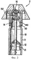
фиг. 1 является видом поперечного сечения в плане, показывающим устройство для дозирования и подачи согласно изобретению, с поршнем в открытом положении;
фиг. 2 является видом поперечного сечения в плане, показывающим устройство для дозирования и подачи согласно изобретению, с поршнем в закрытом положении.The invention will be described with reference to the accompanying drawings, in which:
FIG. 1 is a cross-sectional plan view showing a dispensing and feeding device according to the invention with the piston in the open position;
FIG. 2 is a cross-sectional plan view showing a dispensing and feeding device according to the invention with the piston in the closed position.
Изобретение относится к устройству 1 или 2 для дозирования и подачи жидкости 10. Под жидкостью следует понимать жидкости, имеющие различные вязкости. Предпочтительными жидкостями в предпочтительном примере реализации изобретения являются фармацевтические жидкости, но предусмотрены другие виды применения, например, в устройствах для освежения воздуха. The invention relates to a
Устройство 1 или 2 для дозирования и подачи жидкости содержит емкость 11. Емкость обычно представляет собой полость, в которой должна находиться жидкость 10. В предпочтительном варианте реализации емкость по существу газонепроницаема, что предотвращает или ограничивает химические реакции под воздействием контакта с парами О2 или Н2О, например, или предотвращает попадание воздуха в устройство, что может вызвать нарушения в дозировании и подаче жидкости.The
Устройство для дозирования и подачи также содержит вал 12, обычно представляющий собой удлиненный элемент, имеющий основную ось, проходящую в более удлиненном направлении, причем вал обычно содержит часть, имеющую постоянное поперечное сечение в плоскости, перпендикулярной основной оси, для обеспечения поступательного перемещения заднего уплотнения 13 или имеющую, например, резьбу для обеспечения перемещения по спирали заднего уплотнения 13 вдоль вала 12. The dispensing and feeding device also comprises a
Устройство также содержит заднее уплотнение 13, обеспечивающее возможность герметизации емкости 11 по существу независимо от количества жидкости 10, содержащейся в емкости 11. Это может быть достигнуто, например, посредством выполнения основной части емкости 11 с постоянным поперечным сечением в плоскости, перпендикулярной основной оси вала 12, при этом заднее уплотнение 13 имеет по существу одинаковое поперечное сечение, причем поперечное сечение заднего уплотнения 13 предпочтительно имеет большие размеры по краям, чем постоянное поперечное сечение емкости 11 для обеспечения герметичного уплотнения, так что перемещение заднего уплотнения 13 вдоль вала 12 обеспечивает герметизацию емкости 11 по постоянному поперечному сечению на любом уровне в основной части емкости 11 с постоянным поперечным сечением, что дает возможность герметичного, газонепроницаемого уплотнения, изменяющегося объема. В предпочтительном варианте реализации заднее уплотнение 13 выполнено из гибкого и упругого материала, имеющего форму зонтика, что более предпочтительно, форму двойного зонтика, так что уплотнение постоянно прижато к емкости 11 по периметру поперечного сечения. The device also includes a
Устройство 1 или 2 также содержит амортизатор 14. Амортизатор предпочтительно является деталью, выполненной из гибкого материала и имеющей форму зонтика, складывающегося во время перемещения в одном направлении и амортизирующего во время перемещения в другом направлении. The
В устройство согласно изобретению также включен поршень 151 или 152. Поршень 151 или 152 обычно является деталью, имеющей постоянное поперечное сечение, расположенной в плоскости, перпендикулярной его основной оси, причем этот поршень 151 или 152 выполнен удлиненным вдоль основной оси, перемещается в части емкости 11, которая имеет поперечное сечение в плоскости, перпендикулярной основной оси поршня 151 или 152, которое по существу равно, но предпочтительно меньше по краям, чем поперечное сечение поршня 151 или 152 для обеспечения хорошего уплотнения. Обычно основная ось поршня 151 или 152 параллельна или даже совмещена с основной осью вала 12. Устройство также содержит одноходовой клапан 16. Под одноходовым клапаном следует понимать, что при обычном использовании клапан 16 обеспечивает возможность прохода жидкости только в одном направлении. В предпочтительном варианте реализации клапан 16 является "самоуплотняющимся" клапаном, как описано, например, в основном в ЕР-А-0597601, ЕР-А-0395380 или ЕР-А-0160336. A
Необходимым признаком устройства согласно изобретению является то, что заднее уплотнение 13 герметично уплотняет первый конец емкости 11. Это позволяет использовать газонепроницаемую емкость 11, которая обеспечивает устойчивость жидкого продукта 10 и необходимость работы устройства, как будет описано далее. A necessary feature of the device according to the invention is that the
Заднее уплотнение 13 также должно перемещаться вдоль вала 12, при этом такое перемещение включает, например, линейное или спиральное перемещение. The
Клапан 16 расположен на втором конце емкости 11. Обычно емкость выполнена удлиненной вдоль основного направления вала и содержит только два конца, при этом первый конец герметично перекрывается задним уплотнением 13, а другой включает клапан 16. The
Поршень 151 или 152 закреплен на одном конце вала 12. Обычно поршень 151 или 152 используется в устройстве 1 или 2 согласно изобретению, чтобы протолкнуть дозу 100 продукта в направлении клапана 16. Для этого поршень 151 или 152 расположен между клапаном 16 и амортизатором 14. A
Амортизатор 14 также закреплен на валу 12, при этом он расположен между поршнем 151 или 152 и задним уплотнением 13. Обычно амортизатор 14 расположен в части 110 емкости 11, которая не содержит дозы 100, готовой для дозированной подачи. Обычно устройство 1 или 2 согласно изобретению в основном предназначено для многоразового использования, так что амортизатор 14 установлен в части емкости 11, которая содержит множество доз, которые не готовы для дозированной подачи, поскольку они не находятся между поршнем и клапаном. Следует заметить, что устройство 1 или 2 может использоваться для одноразового использования. The
Чтобы устройство согласно изобретению было функциональным, поршень 151 или 152 имеет открытое положение и закрытое положение, причем открытое положение обеспечивает сообщение по жидкости 153 между клапаном 16 и частью емкости 11 между поршнем 151 и задним уплотнением 13. Это сообщение по жидкости 153 обеспечивает размещение дозы продукта 100 между клапаном 16 и поршнем 151 перед дозированием и подачей. In order for the device according to the invention to be functional, the
Перемещение поршня между открытым и закрытым положением обеспечивается перемещением вала 12 вдоль своей собственной оси, которая является основной осью. Давление в зоне, расположенной между клапаном 16 и поршнем, уменьшается, когда поршень движется из своего закрытого положения в направлении его открытого положения, в результате чего создается частичный вакуум. Это позволяет "всасывать" дозу 100 продукта из части емкости 11, расположенной между поршнем и задним уплотнением, в часть между клапаном и поршнем, когда поршень движется в открытое положение. The movement of the piston between the open and closed position is provided by the movement of the
Амортизатор 14 складывается, когда поршень движется из его закрытого положения в направлении его открытого положения. Это позволяет упростить подготовку к дозированной подаче и предотвращает избыточные, действующие в противоположном направлении усилия, когда оператор приводит в действие устройство, вследствие чего движение или перемещение поршня из его закрытого положения в направлении его открытого положения обеспечивает сообщение по жидкости 153 между частью емкости между поршнем и задним уплотнением и частью между клапаном и поршнем, чтобы заполнить эту последнюю часть жидкостью посредством уменьшения давления или создания частичного вакуума, упомянутого выше, при этом доза 100 продукта "всасывается" в эту часть под влиянием разрежения посредством сообщения по жидкости 153 в готовом виде для дозированной подачи под воздействием толчка поршня через клапан. The
Поскольку единственным потоком жидкости из части емкости, расположенной между амортизатором и задним уплотнением и частью емкости, расположенной на другой стороне амортизатора, является поток, проходящий через соединительный канал 140, расположенный в амортизаторе 14, когда поршень движется из своего открытого положения в направлении своего закрытого положения, при этом такое движение, приводящее к подаче готовой для подачи жидкости, затормаживается посредством ограничения потока жидкости в соединительном канале 140, расположенном в амортизаторе 14. Обычно для подачи дозы 100, расположенной между поршнем и клапаном 16, поршень должен перемещаться из своего открытого положения в направлении своего закрытого положения, таким образом перемещая амортизатор 14, поскольку как амортизатор 14, так и поршень закреплены на валу 12, при этом амортизатор перемещается через жидкость 10, создавая тем самым неравновесность в герметично закрытой емкости 11 между частью емкости, расположенной между амортизатором 14 и задним уплотнением 13, и частью емкости 11, расположенной между амортизатором 14 и поршнем, причем эта неравновесность компенсируется потоком в соединительном канале 140, расположенном в амортизаторе 14, обеспечивая регулирование скорости выброса или подачи дозы 100, готовой для дозирования и подачи через клапан 16 под воздействием движения поршня. Действительно, поршень будет иметь максимальную скорость, зависящую от способности сжатия, и главным образом от вязкости жидкости, а также от геометрических и/или механических свойств устройства. Например, чем больше соединительный канал 140, или чем больше прикладываемое направленное вперед на вал 12 усилие, тем выше максимальная скорость. Since the only fluid flow from the portion of the reservoir located between the shock absorber and the rear seal and the portion of the reservoir located on the other side of the shock absorber is the flow through the connecting
В предпочтительном варианте реализации вал выполнен из материала, проводящего электричество, как, например, металл. В более предпочтительном варианте реализации жидкость перед дозированием и подачей заряжается электричеством. Устройство согласно изобретению особенно подходит для такого использования, поскольку зарядке жидкости будет способствовать регулирование потока. В частности, существует максимальная скорость, превышение которой затрудняет зарядку жидкости или делает ее невозможной, поэтому заторможенная подача обеспечивает хорошую зарядку. Предпочтительно, скорость зарядки соответствует скорости потока жидкости для достижения эффективного электрогидродинамического распыления жидкости. In a preferred embodiment, the shaft is made of a material that conducts electricity, such as metal. In a more preferred embodiment, the liquid is charged with electricity before dosing and feeding. The device according to the invention is particularly suitable for such use, since the regulation of flow will contribute to the charging of the liquid. In particular, there is a maximum speed, the excess of which makes it difficult to charge the liquid or makes it impossible, therefore, the inhibited flow ensures good charging. Preferably, the charging rate corresponds to a fluid flow rate to achieve effective electro-hydrodynamic atomization of the liquid.
В предпочтительном варианте реализации объем, находящийся между поршнем в открытом положении и клапаном составляет менее 100 мкл. In a preferred embodiment, the volume between the piston in the open position and the valve is less than 100 μl.
В другом предпочтительном варианте реализации регулирование подачи таково, что объем дозированной подаваемой жидкости при каждой операции дозирования и подачи изменяется менее чем на 10% между каждой операцией дозирования и подачи. Более предпочтительно, изменение составляет менее 5%. In another preferred embodiment, the control of the supply is such that the volume of the dosed feed liquid at each dosing and supplying operation changes by less than 10% between each dosing and supplying operation. More preferably, the change is less than 5%.
В следующем предпочтительном варианте реализации изобретения на конце вала, противоположном тому, на котором закреплен поршень, размещена сжатая пружина, которая обеспечивает усилие на вал в направлении, по существу параллельном оси вала. In a further preferred embodiment of the invention, a compressed spring is placed on the shaft end opposite to the one on which the piston is mounted, which provides a force on the shaft in a direction substantially parallel to the shaft axis.
В дополнительном предпочтительном варианте реализации соединительный канал является единственным отверстием, выполненным в амортизаторе, более предпочтительно, круглым отверстием. In a further preferred embodiment, the connecting channel is a single hole formed in the shock absorber, more preferably a circular hole.
Наиболее предпочтительный вариант реализации изобретения обеспечивается посредством объединения устройства согласно изобретению с распылительным устройством, описанным в находящихся на рассмотрении заявках GB 9806937.0 и GB 9806939.6. The most preferred embodiment of the invention is provided by combining the device according to the invention with the spray device described in pending applications GB 9806937.0 and GB 9806939.6.
Такое распылительное устройство особенно подходит для лечения заболеваний области носа, как, например, сенная лихорадка/ или застоев, связанных с простудой. В последнее время было признано, что слизистые оболочки носовой полости могут использоваться как удобные участки передачи лекарств, необходимых для лечения других участков тела. Например, в публикации WO 92/11049 описано устройство в виде ручки для применения через нос, в частности, инсулина. Для лечения такого типа заболевания часто удобно использование распылителя. Лечение глаз может также удобно осуществляться посредством распылительного устройства. Предпочтительные объемы доз для таких видов применения обычно небольшие, менее чем 10 мкл. Обычно для эффективного лечения требуется повторная дозировка. Достижение чистого пуска и остановки потока в распылительных устройствах, подающих такие небольшие объемы, может оказаться сложным. Типичные проблемы, с которыми обычно встречаются, включают остаточное истечение из клапана после использования, с возможностью загрязнения исходного материала, и забивку клапана. Such a spray device is particularly suitable for treating diseases of the nose, such as hay fever / or colds associated with colds. Recently, it has been recognized that mucous membranes of the nasal cavity can be used as convenient sites for the transfer of drugs needed to treat other parts of the body. For example, WO 92/11049 describes a pen-shaped device for use through the nose, in particular insulin. For the treatment of this type of disease, it is often convenient to use a nebulizer. Eye treatment can also be conveniently carried out by means of a spray device. Preferred dose volumes for these uses are usually small, less than 10 μl. Usually, repeated dosage is required for effective treatment. Achieving a clean start and stop flow in spray devices that deliver such small volumes can be difficult. Typical problems that are commonly encountered include residual outflow from the valve after use, with the possibility of contamination of the starting material, and clogging of the valve.
Использование эластомерного клапана, в частности, щелевого клапана, обеспечивает чистые пуск и остановку потока без забивки, особенно клапана (для чистого пуска) с резким падением давления через участок сброса давления (для чистой остановки), даже если распыляемая жидкость содержит тонкодисперсный материал с твердыми макрочастицами. The use of an elastomeric valve, in particular a slotted valve, ensures clean start and stop of the flow without clogging, especially a valve (for clean start) with a sharp drop in pressure through the pressure relief section (for clean stop), even if the sprayed liquid contains fine particulate matter with solid particulates .
Предпочтительно, распылительное устройство предназначено для обеспечения одной или более единиц дозы жидкости, причем каждая доза имеет объем в пределах приблизительно от 1 до 100 мкл, при этом устройство содержит эластомерный, самоуплотняющийся клапан, имеющий сторону для жидкости и сторону для подачи, при этом клапан открывается для обеспечения прохода жидкости, когда к жидкости на стороне для жидкости прикладывается давление, и герметично закрывается, когда давление снимается. Preferably, the spray device is intended to provide one or more units of a dose of liquid, each dose having a volume in the range of about 1 to 100 μl, the device comprising an elastomeric, self-sealing valve having a liquid side and a supply side, wherein the valve opens to allow fluid to pass when pressure is applied to the liquid on the liquid side, and sealed when pressure is relieved.
Предпочтительно распылительное устройство является электростатичным распылительным устройством, которое заряжает распыляемое вещество перед попаданием в ноздри. Preferably, the nebulizing device is an electrostatic nebulizing device that charges the nebulized substance before entering the nostrils.
Жидкотекучие среды. Fluid media.
Устройство согласно изобретению предпочтительно включает емкость для жидкости, содержащую фармацевтически приемлемую жидкость, включающую фармацевтически приемлемое лечебное вещество, выбранное из лекарственных препаратов, ароматизирующие вещества, соли, поверхностно-активные вещества и их смеси. Жидкость по выбору содержит другие иммуногенные вещества, растворенные или распыленные в ней. Жидкость может быть водной или неводной. Водные жидкости включают воду и смеси воды со смешивающимися с водой растворителями, как, например, глицерин, пропиленгликоль или спирты, например, этаноловый спирт или изопропиловый спирт. Могут также использоваться водные эмульсии, либо водомасляные эмульсии, либо эмульсии масла в воде. Предпочтительно жидкость является водным раствором, дисперсией или эмульсией масла в воде. Неводные жидкости содержат полиэтиленгликоли, глицерин, пропиленгликоль, диметилизосорбид, силиконовые масла, кетоны, простые эфиры и их смеси. The device according to the invention preferably includes a liquid container containing a pharmaceutically acceptable liquid, including a pharmaceutically acceptable therapeutic substance selected from drugs, flavoring agents, salts, salts, surfactants and mixtures thereof. The fluid optionally contains other immunogenic substances dissolved or sprayed therein. The fluid may be aqueous or non-aqueous. Aqueous liquids include water and mixtures of water with water-miscible solvents, such as, for example, glycerol, propylene glycol or alcohols, for example ethanol or isopropyl alcohol. Aqueous emulsions, or oil-water emulsions, or oil-in-water emulsions may also be used. Preferably, the liquid is an aqueous solution, dispersion or emulsion of an oil in water. Non-aqueous liquids contain polyethylene glycols, glycerin, propylene glycol, dimethyl isosorbide, silicone oils, ketones, ethers and mixtures thereof.
Несмотря на то, что изобретение не ограничено каким-либо конкретным диапазоном удельного сопротивления, оно особенно применимо с жидкостями, имеющими низкое удельное сопротивление, особенно с такими, которые имеют объемное удельное сопротивление менее 1•108 Ом•см, предпочтительно менее 1•104 Ом•см, более предпочтительно, менее 1•103 Ом•см. В случае необходимости жидкость может содержать модификатор удельного сопротивления, как, например, фармацевтическую соль, для доведения объемного удельного сопротивления до необходимого уровня.Although the invention is not limited to any specific resistivity range, it is particularly applicable to liquids having a low resistivity, especially those having a volume resistivity of less than 1 • 10 8 Ohm • cm, preferably less than 1 • 10 4 ohm • cm, more preferably less than 1 • 10 3 ohm • cm. If necessary, the liquid may contain a resistivity modifier, such as a pharmaceutical salt, to bring the volume resistivity to the desired level.
Жидкость представляет собой фармацевтически приемлемый внутриносовой препарат. Предпочтительно, лекарственный состав для носа является изотоническим, то есть он имеет такое же осмотическое давление, что и кровь, и жидкость слезоотделения. Необходимая изотоничность составов этого изобретения может быть достигнута, например, посредством использования хлорида натрия или других фармацевтически приемлемых агентов, как, например, декстроза, борная кислота, лимонная кислота, цитрат натрия, тартрат натрия, фосфат натрия, фосфат калия, пропиленгликоль или другие неорганические и органические растворенные вещества. Хлорид натрия предпочтителен особенно для буферных растворов, содержащих ионы натрия. Другие примеры эквивалентов хлорида натрия описаны в книге "Фармацевтические теории Ремингтона", стр. 1491-1497, 18-е изд-е, 1990 г. (Remington's Pharmaceutical Sciences, pp. 1491-1497, Alfonso Gennaro, 18th ed, 1990), которая включена для ссылки.A fluid is a pharmaceutically acceptable intranasal preparation. Preferably, the nasal formulation is isotonic, that is, it has the same osmotic pressure as the blood and tear fluid. The necessary isotonicity of the compositions of this invention can be achieved, for example, by using sodium chloride or other pharmaceutically acceptable agents, such as dextrose, boric acid, citric acid, sodium citrate, sodium tartrate, sodium phosphate, potassium phosphate, propylene glycol or other inorganic and organic solutes. Sodium chloride is preferred especially for buffer solutions containing sodium ions. Other examples of sodium chloride equivalents are described in Remington's Pharmaceutical Theories, pp. 1491-1497, 18th ed., 1990 (Remington's Pharmaceutical Sciences, pp. 1491-1497, Alfonso Gennaro, 18 th ed, 1990) which is included for reference.
Лекарственные препараты. Medications.
Жидкость может содержать широкий диапазон лекарственных препаратов. Под "лекарственным препаратом" подразумевается лекарство или другое вещество, предназначенное для терапевтического воздействия на тело. Подходящие уровни лекарства составляют от 0,001 до 20%, предпочтительно от 0,01 до 5%, более предпочтительно, от 0,1 до 5%. Уровни специфических лекарственных препаратов будут зависеть от множества факторов, включая их возможности, безопасность, растворимость, простоту распыления и должный эффект. При использовании лекарственный препарат может быть таким, который рассчитан на воздействие в участке нанесения, например в качестве противоотечного средства, антигистаминного или противовоспалительного средства, или же он может быть предназначен для систематического всасывания, как, например, антивирусное средство антидепрессант, противорвотное средство, жаропонижающее средство или гормональное средство, и тому подобное. Лекарственный препарат может быть растворимым в жидкости или может быть жидкостью, содержащей нерастворимые, тонкодисперсные макрочастицы или твердые вещества, распыленные в жидкости. The fluid may contain a wide range of medications. By "medicament" is meant a medicine or other substance intended for therapeutic effect on the body. Suitable drug levels are from 0.001 to 20%, preferably from 0.01 to 5%, more preferably from 0.1 to 5%. The levels of specific drugs will depend on many factors, including their capabilities, safety, solubility, ease of spraying, and proper effect. When used, the drug can be one that is designed to act in the area of application, for example, as a decongestant, antihistamine or anti-inflammatory drug, or it can be designed for systematic absorption, such as an antiviral agent, antidepressant, antiemetic, antipyretic or a hormonal agent, and the like. The drug may be soluble in the liquid or may be a liquid containing insoluble, finely divided particles or solids sprayed into the liquid.
Противоотечные (противозастойные) лекарственные препараты включают оксиметазолин, трамазолин, ксилометазолин, нафазолин, тетрагидразолин, псевдоэфедрин, эфедрин, фенилэфрин, их фармацевтически приемлемые соли, как, например, гидрохлориды и их смеси. Предпочтительные противоотечные лекарственные препараты выбраны из оксиметазолина, ксилометазолина, их фармацевтических солей и их смесей. Особенно предпочтительным для использования здесь является гидрохлорид оксиметазолина, который растворим в воде. При использовании в составах настоящего изобретения противоотечный лекарственный препарат преимущественно присутствует в концентрации приблизительно от 0,01% до 3,0%, более предпочтительно, приблизительно от 0,01% до 1%. Decongestants (decongestants) drugs include oxymetazoline, tramazoline, xylometazoline, naphazoline, tetrahydrazoline, pseudoephedrine, ephedrine, phenylephrine, their pharmaceutically acceptable salts, such as hydrochlorides and mixtures thereof. Preferred decongestants are selected from oxymetazoline, xylometazoline, their pharmaceutical salts and mixtures thereof. Particularly preferred for use herein is oxymetazoline hydrochloride, which is soluble in water. When used in the compositions of the present invention, the decongestant drug is preferably present in a concentration of from about 0.01% to 3.0%, more preferably from about 0.01% to 1%.
Антигистамины, используемые в настоящем изобретении, включают, не ограничиваясь этим, быстродействующие вещества-антагонисты рецептора гистамина Н-1. Такие антигистамины могут быть выбраны из следующих групп антигистаминов: алкиламинов, этаноламинов, этилендиаминов, пиперазинов, фенотиазинов, пиперидинов. Примеры быстродействующих антигистаминов включают акривастин, карбиноксамин, дифенгидрамин, хлорофенирамин, бромфенирамин, дексхлорофенирамин, доксиламин, клемастин, прометазин, тримепразин, метдилазин, гидроксизин, пириламин, трепеленнамин, меклизин, трипролидин, азатадин, ципрогептадин, рокастин, фениндамин или их фармацевтически приемлемые соли и смеси. Другие антигистамины включают терфенадин, азеластин, цетиризин, астемизол, эбастин, кетотифен, лодоксамид, лоратадин, левокабастин, меквитазин, оксатомид, сетастин, тазифиллин, темеластин или их фармацевтически приемлемые соли и смеси. При использовании в составах настоящего изобретения компонент антигистамина предпочтительно присутствует в концентрации приблизительно от 0,01 до 3%, более предпочтительно, приблизительно от 0,01 до 1%. Antihistamines used in the present invention include, but are not limited to, the fast acting histamine H-1 receptor antagonists. Such antihistamines can be selected from the following groups of antihistamines: alkylamines, ethanolamines, ethylenediamines, piperazines, phenothiazines, piperidines. Examples of high-speed antihistamines include acrivastin, carbinoxamine, diphenhydramine, chloropheniramine, brompheniramine, dexchloropheniramine, doxylamine, clemastine, promethazine, trimeprazine, methyldazine, hydroxyzine, pyrilamine, pharmacinidine, ilipinidinpropyl azindepine, trimedinidinpropylamine, tride azinde palinpropylamine, tripledinamine, tripid azide . Other antihistamines include terfenadine, azelastine, cetirizine, astemizole, ebastine, ketotifen, lodoxamide, loratadine, levocabastine, mequitazine, oxatomide, setastine, tazifillin, temelastine or their pharmaceutically acceptable salts and mixtures thereof. When used in the compositions of the present invention, the antihistamine component is preferably present in a concentration of from about 0.01 to 3%, more preferably from about 0.01 to 1%.
Лекарственный препарат может также быть противовоспалительным средством, как, например, кортикостероид. Особенно предпочтительными средствами, входящими в этот класс, являются глюкокортикоиды, выбранные из группы, состоящей из беклометазона, флунисолида, флутиказона, меметазона, будесонида, их фармацевтически приемлемые соли и смеси. При использовании в составах настоящего изобретения противовоспалительное средство предпочтительно присутствует в концентрации приблизительно от 0,001% приблизительно до 0,1%, более предпочтительно, приблизительно от 0,01% приблизительно до 0,1%. The drug may also be an anti-inflammatory agent, such as, for example, a corticosteroid. Particularly preferred agents in this class are glucocorticoids selected from the group consisting of beclomethasone, flunisolide, fluticasone, memethasone, budesonide, their pharmaceutically acceptable salts and mixtures thereof. When used in the compositions of the present invention, the anti-inflammatory agent is preferably present in a concentration of from about 0.001% to about 0.1%, more preferably from about 0.01% to about 0.1%.
Также целесообразно используются производные ксантина, как, например, кофеин и метилксантин и ему подобные; антиаллергические средства; противогрибковые средства, антихолинергические средства, неопиатные анализирующие средства, такие как ацетаминофен, ацетилсалициловая кислота, ибупрофен, этодолак, фенбупрофен, фенопрофен, кеторолак, флурбипрофен, индометацин, кетопрофен, напроксен, их фармацевтически приемлемые соли и смеси; опиатные аналгизирующие средства, такие как бутарфанол; вещества-антагонисты рецептора лейкотриена; стабилизаторы клеток молочных желез, как, например, кромолиннатрий, недокромил и лодоксамид; соединения, подавляющие липоксигеназу; и никотин, инсулин и кальцинотин. Xanthine derivatives such as caffeine and methylxanthine and the like are also useful; antiallergic drugs; antifungal agents, anticholinergics, non-opiate analyzing agents such as acetaminophen, acetylsalicylic acid, ibuprofen, ethodolac, fenbuprofen, phenoprofen, ketorolac, flurbiprofen, indomethacin, ketoprofen, naproxen, their pharmaceutically acceptable salts and mixtures thereof; opiate analgesics such as butarfanol; leukotriene receptor antagonists; breast cell stabilizers, such as cromolyn sodium, nedocromil and lodoxamide; lipoxygenase inhibiting compounds; and nicotine, insulin and calcinotine.
Другие примеры лекарственных препаратов упомянуты в публикациях: WO 97/46243, ER-A-780127, US-A-5124315, US-A-5622724, US-A-5656255 и US-A-5705490. Other examples of medications are mentioned in publications: WO 97/46243, ER-A-780127, US-A-5124315, US-A-5622724, US-A-5656255 and US-A-5705490.
Ароматические вещества. Aromatic substances.
Различные ароматические компоненты (например, альдегиды и эфиры) могут использоваться в жидкостях согласно изобретению. Они включают, например, ментол, камфору, эвкалиптол, бензальдегид (вишня, миндаль); цитраль (лимон, лайм); нераль, деканаль (апельсин, лимон); альдегид С-8, альдегид С-9 и альдегид С-12 (цитрусовые фрукты); толилальдегид (вишня, миндаль); 2,6-диметил-октанал (зеленые фрукты); 2-додеценал (цитрус, мандарин); и травяные компоненты, такие как чабрец, розмарин и шалфейные масла. Дополнительные ароматические компоненты, используемые в настоящем изобретении, включают компоненты, описанные в патентах США 4136163, 4459425 и 4230688, которые включены в качестве ссылки. Также могут использоваться смеси этих ароматизирующих веществ. Various aromatic components (e.g. aldehydes and esters) can be used in the fluids of the invention. These include, for example, menthol, camphor, eucalyptol, benzaldehyde (cherry, almond); citral (lemon, lime); neral, decanal (orange, lemon); aldehyde C-8, aldehyde C-9 and aldehyde C-12 (citrus fruits); tolaldehyde (cherry, almond); 2,6-dimethyl octanal (green fruits); 2-dodecenal (citrus, mandarin); and herbal ingredients such as thyme, rosemary and sage oils. Additional aromatic components used in the present invention include those described in US Pat. Nos. 4,136,163, 4,459,425 and 4,230,688, which are incorporated by reference. Mixtures of these flavoring agents may also be used.
Поверхностно-активные вещества. Surfactants.
Жидкость может также содержать одно или более фармацевтически приемлемое поверхностно-активное вещество. Такие поверхностно-активные вещества могут быть необходимыми для распыления или эмульгирования лекарственных препаратов или ароматизирующих агентов для увеличения поглощения на носовой перегородке, или в качестве лечебного средства, например для смягчения ушной серы. Поверхностно-активные вещества могут быть анионные, неионные, катионные или амфотерные, предпочтительно неионные. Типичные неионные поверхностно-активные вещества, используемые здесь, включают: производные полиоксиэтилена частичных эфиров жирных кислот сорбитолангидридов, например, полисорбат 80; производные полиоксиэтилена жирных кислот, например стеарат полиоксиэтилена 50; а также оксиэтилированный третичный октилфенолформальдегидный полимер (фирмы Sterling Organics с коммерческим названием Tyloxapol) или их смеси. Обычная концентрация составляет приблизительно от 0,1 до 3 вес.%. The fluid may also contain one or more pharmaceutically acceptable surfactants. Such surfactants may be necessary to spray or emulsify drugs or flavoring agents to increase absorption on the nasal septum, or as a therapeutic agent, for example, to soften ear wax. Surfactants may be anionic, nonionic, cationic or amphoteric, preferably nonionic. Typical non-ionic surfactants used herein include: polyoxyethylene derivatives of partial esters of sorbitol anhydride fatty acids, for example, polysorbate 80; derivatives of polyoxyethylene fatty acids, for example polyoxyethylene stearate 50; as well as an ethoxylated tertiary octylphenol formaldehyde polymer (Sterling Organics with the trade name Tyloxapol) or mixtures thereof. A typical concentration is from about 0.1 to 3% by weight.
Соли. Salt.
Жидкость также может содержать одну или более фармацевтически приемлемых солей. Соли могут быть минеральными, как, например, хлорид натрия, или солями органических кислот, как, например, цитрат натрия. The fluid may also contain one or more pharmaceutically acceptable salts. Salts may be mineral, such as sodium chloride, or organic acid salts, such as sodium citrate.
Другие активирующие добавки. Other activating additives.
Жидкость может также содержать другие ингредиенты, как, например, уплотнители, увлажнители, лекарственные суспензии, средства инкапсуляции, хелатные агенты и консерванты. The liquid may also contain other ingredients, such as, for example, sealants, humectants, drug suspensions, encapsulation agents, chelating agents and preservatives.
Вязкость составов может сохраняться на выбранном уровне посредством использования фармацевтически приемлемого уплотняющего агента. Уплотнители включают, например, ксантановую смолу, метилцеллюлозу, микрокристаллическую целлюлозу, карбоксиметилцеллюлозу, хитозан, гидроксипропилцеллюлозу, гидроксипропилметилцеллюлозу, гидроксиметилцеллюлозу, гидроксиэтилцеллюлозу, карбоксивиниловый полимер, карбомер и т.д. или их фармацевтически приемлемые соли. Смеси таких уплотняющих агентов также могут быть использованы. Предпочтительная концентрация уплотнителя будет зависеть от выбранного агента. Важно использовать количество, с помощью которого будет достигнута выбранная вязкость. Вязкие составы обычно приготавливаются из растворов посредством добавления таких уплотняющих агентов. The viscosity of the compositions can be maintained at a selected level through the use of a pharmaceutically acceptable sealing agent. Sealers include, for example, xanthan gum, methyl cellulose, microcrystalline cellulose, carboxymethyl cellulose, chitosan, hydroxypropyl cellulose, hydroxypropyl methyl cellulose, hydroxymethyl cellulose, hydroxyethyl cellulose, carboxyvinyl polymer, carbomer, etc. or their pharmaceutically acceptable salts. Mixtures of such sealing agents can also be used. The preferred concentration of sealant will depend on the agent selected. It is important to use the amount by which the selected viscosity is achieved. Viscous formulations are usually prepared from solutions by the addition of such sealing agents.
Жидкости, используемые в настоящем изобретении, могут также содержать приблизительно от 0,01% до приблизительно 5% увлажнителя для предотвращения высыхания слизистой оболочки и раздражения. Любые разнообразные фармацевтически приемлемые увлажнители могут применяться, включая, например, сорбитол, пропиленгликоль, полиэтиленгликоль, глицерин или их смеси. Что касается уплотнителей, концентрации будут изменяться в зависимости от выбранного агента, хотя наличие или отсутствие этих агентов или их концентрация не является существенным признаком изобретения. The fluids used in the present invention may also contain from about 0.01% to about 5% humectant to prevent mucosal drying and irritation. Any variety of pharmaceutically acceptable humectants may be used, including, for example, sorbitol, propylene glycol, polyethylene glycol, glycerin, or mixtures thereof. As for sealants, concentrations will vary depending on the agent selected, although the presence or absence of these agents or their concentration is not an essential feature of the invention.
Фармацевтически приемлемый консервант обычно используется для увеличения срока хранения составов согласно настоящему изобретению. Могут использоваться разнообразные консерванты, включая, например, бензиловый спирт, парабен, фенилэтиловый спирт, тимеросал, хлоробутанол, глюконат хлоргексидина или хлорид бензалкония. Наиболее предпочтительная система консерванта, используемая здесь, содержит сочетание хлорида бензалкония, глюконата хлоргексидина с двухнатриевой этилендиаминтетрауксусной кислотой в качестве хелатного агента. Подходящая концентрация консерванта будет от 0,001% до 2% на основе общей массы, несмотря на то, что могут быть значительные изменения в зависимости от выбранного агента. A pharmaceutically acceptable preservative is typically used to extend the shelf life of the formulations of the present invention. A variety of preservatives may be used, including, for example, benzyl alcohol, paraben, phenylethyl alcohol, thimerosal, chlorobutanol, chlorhexidine gluconate or benzalkonium chloride. The most preferred preservative system used here contains a combination of benzalkonium chloride, chlorhexidine gluconate and disodium ethylenediaminetetraacetic acid as a chelating agent. A suitable preservative concentration will be from 0.001% to 2% based on the total weight, although there may be significant changes depending on the agent selected.
Устройство предназначено для обеспечения одной или более единиц дозы жидкости, предпочтительно, нескольких доз жидкости, каждая предпочтительно объемом в пределах приблизительно от 1 до приблизительно 100 мкл, более предпочтительно, приблизительно от 1 до приблизительно 20 мкл, еще более предпочтительно, приблизительно от 5 до приблизительно 15 мкл. Объем дозы предпочтительно установлен заранее, но может регулироваться пользователем до нужного объема. Предпочтительно устройство представляет собой сменный элемент, который может быть частью более крупного устройства и который можно сменить или заменить. The device is intended to provide one or more units of a dose of liquid, preferably several doses of liquid, each preferably with a volume in the range of from about 1 to about 100 μl, more preferably from about 1 to about 20 μl, even more preferably from about 5 to about 15 μl The dose volume is preferably set in advance, but can be adjusted by the user to the desired volume. Preferably, the device is a replaceable element that can be part of a larger device and which can be replaced or replaced.
Предпочтительно устройство предназначено для обеспечения распыления вещества, имеющего связь по жидкости, проходящую от носика и имеющую конец носика и конец подачи, при этом пульверизатор также содержит распиливающий конус, расходящийся от конца подачи связи. Под "концом носика" подразумевается точка, в которой плоскость (далее называемая плоскость носика), проходящая перпендикулярно к оси связи и только касающаяся внешней поверхности носика, будет пересекать центр связи. Связь предпочтительно имеет длину приблизительно от 1 до 20 мм, более предпочтительно приблизительно от 1 до приблизительно 10 мм, однако более предпочтительно, приблизительно от 2 до приблизительно 8 мм, и особенно, приблизительно от 3 до приблизительно 6 мм от конца носика до конца подачи. Preferably, the device is designed to provide a spray of a substance having a fluid connection extending from the nozzle and having a nozzle end and a feed end, the spray gun also having a sawing cone diverging from the end of the bond supply. By "tip of the nose" is meant the point at which a plane (hereinafter referred to as the nose plane), perpendicular to the axis of communication and only touching the outer surface of the nose, will intersect the center of communication. The bond preferably has a length of from about 1 to 20 mm, more preferably from about 1 to about 10 mm, but more preferably, from about 2 to about 8 mm, and especially from about 3 to about 6 mm from the end of the spout to the end of the feed.
В предпочтительных вариантах реализации распиливающий конус имеет угол конусности приблизительно от 10 до приблизительно 90o, предпочтительно от 20 до приблизительно 50o, более предпочтительно, приблизительно от 30 до приблизительно 40o. В электростатических устройствах длина связи и угол конусности могут регулироваться изменением вязкости или поверхностного натяжения жидкости, изменением скорости струи жидкости или выходной скорости, или изменением характеристик щели клапана или свойств материала клапана, или изменением силы электрического поля посредством напряжения, градиента электрического потенциала, или использованием усиливающего поле электрода.In preferred embodiments, the sawing cone has a taper angle of from about 10 to about 90 ° , preferably from 20 to about 50 ° , more preferably from about 30 to about 40 ° . In electrostatic devices, the bond length and taper angle can be controlled by changing the viscosity or surface tension of the liquid, changing the speed of the liquid stream or the output speed, or changing the characteristics of the valve slit or the properties of the valve material, or changing the strength of the electric field by means of a voltage, an electric potential gradient, or using a gain electrode field.
Общая длина связи может быть больше и предпочтительно превышает длину от конца носика до конца подачи, поскольку связь предпочтительно начинается от точки на устройстве со стороны плоскости носика, как, например, от выполненного из эластомерного материала самоуплотняющегося клапана, описанного здесь, и проходит через канал в носике. Целесообразно, расстояние от точки начала связи до плоскости носика составляет приблизительно от 2 мм приблизительно до 15 мм, предпочтительно приблизительно от 3 до приблизительно 10 мм, и более предпочтительно, приблизительно от 5 до приблизительно 9 мм. Таким образом носик может использоваться как усилитель поля, который помогает регулировать длину связи. Для этой цели носик предпочтительно выполнен не из проводникового материала, как, например, из пластика, которым может быть полипропилен, но предпочтительно является мягким термопластичным эластомером, который обеспечивает больше удобства при его удержании у носа. Эластомеры, описанные здесь и используемые для самоуплотняющегося клапана, также подходят для носика. The total bond length can be longer and preferably greater than the length from the end of the nozzle to the end of the feed, since the connection preferably starts from a point on the device from the side of the plane of the nozzle, such as, for example, from a self-sealing valve made of elastomeric material and passes through a channel in nose. Suitably, the distance from the starting point of the bond to the nose plane is from about 2 mm to about 15 mm, preferably from about 3 to about 10 mm, and more preferably from about 5 to about 9 mm. Thus, the spout can be used as a field amplifier, which helps to adjust the length of the connection. For this purpose, the nozzle is preferably made not of a conductive material, such as, for example, plastic, which may be polypropylene, but is preferably a soft thermoplastic elastomer, which provides more convenience when holding it near the nose. The elastomers described herein and used for the self-sealing valve are also suitable for the nozzle.
Эластомерные устройства, подходящие для распыления при помощи связи, описаны в WO 96/40441, в ЕР-А-501725 и в совместно рассматриваемой заявке PCT/GB 97/02746. Предпочтительно устройство согласно изобретению является устройством согласно примерам выполнения заявок ЕР-А-501725 и PCT/GB 97/02746, в которых посредством механических средств создается высокоскоростная струя и приложенное высокое напряжение приводит к тому, что струя или связь преломляется в распыливающий конус. Подходящие скорости струи составляют приблизительно от 0,5 до приблизительно 8, предпочтительно приблизительно от 1 до приблизительно 3 мс-1.Elastomeric devices suitable for sputtering by communication are described in WO 96/40441, in EP-A-501725 and in co-pending application PCT / GB 97/02746. Preferably, the device according to the invention is a device according to exemplary applications EP-A-501725 and PCT / GB 97/02746, in which a high-speed jet is generated by mechanical means and an applied high voltage causes the stream or bond to refract into the spray cone. Suitable jet speeds are from about 0.5 to about 8, preferably from about 1 to about 3 ms -1 .
Подходящее высокое напряжение находится в диапазоне приблизительно от 1 кВ до приблизительно 15 кВ, предпочтительно приблизительно от 2 кВ до приблизительно 10 кВ, и более предпочтительно, приблизительно от 2 кВ до приблизительно 5 кВ. Напряжение может быть приложено даже в небольшом ручном устройстве с помощью батарейки низкого напряжения (1,5 В достаточно), соединенной с повышающим трансформатором. Батарейка предпочтительно является длительного действия и может быть сменной. Генератор может приводиться в действие пользователем с помощью расположенного снаружи переключателя, который также может использоваться для механической накачки насоса. Предпочтительно переключатель включает металлическую часть, с помощью которой пользователь замыкает возврат тока через землю в цепь высокого напряжения. Подходящее устройство для всей конструкции описано в заявке PCT/GB 97/02746. Таким образом, пользователь не получает суммарный заряд. Альтернативные устройства, с помощью которых возбуждается переменное напряжение, также могут использоваться для предотвращения нарастания заряда. Suitable high voltage ranges from about 1 kV to about 15 kV, preferably from about 2 kV to about 10 kV, and more preferably from about 2 kV to about 5 kV. Voltage can be applied even in a small hand-held device using a low-voltage battery (1.5 V is enough) connected to a step-up transformer. The battery is preferably long acting and can be replaceable. The generator can be driven by the user using an external switch, which can also be used to mechanically pump the pump. Preferably, the switch includes a metal part with which the user closes the return of current through the earth to the high voltage circuit. A suitable device for the entire structure is described in PCT / GB 97/02746. Thus, the user does not receive the total charge. Alternative devices by which an alternating voltage is excited can also be used to prevent charge buildup.
Устройство предпочтительно приводится в действие для подачи распыленного вещества. Связь, подающая распыляемое вещество, проходит через отверстие ноздри носа и предпочтительно подходит близко к отверстию носового клапана, прежде чем она прерывается, образуя распыливающий конус. The device is preferably actuated to supply atomized material. The bond supplying the nebulized substance passes through the opening of the nostril of the nose and preferably comes close to the opening of the nasal valve before it breaks to form a spray cone.
Для обеспечения четкого отключения при низких единицах объема устройство предпочтительно содержит эластомерный, самоуплотняющийся выпускной клапан, имеющий сторону жидкости и сторону подачи, при этом клапан открывается для прохода жидкости при воздействии давления на жидкость на стороне жидкости и герметично перекрывается, когда давление снимается. Предпочтительно, четкое отключение достигается при завершении движения вперед поршня в камере сброса давления (участке более широкого диаметра), в результате чего давление резко падает и клапан закрывается. Под "выпускным клапаном" подразумевается эластомерный клапан конечной подачи, при этом устройство не имеет других элементов, которые механически ограничивают или изменяют поток жидкости на расположенной ниже по ходу струи стороне клапана. В особенно предпочтительных вариантах реализации изобретения здесь клапан является щелевым клапаном. Клапан может содержать одну щель или более пересекающихся щелей для образования, например, крестообразной формы. Предпочтительно, однако, чтобы клапан имел одну щель. Несмотря на то, что клапан может быть плоским, предпочтительно он имеет форму купола, что означает, что клапан имеет не плоскостную форму с полостью, имеющей форму полукруглого купола или в форме усеченного конуса. В предпочтительных вариантах реализации клапан по существу имеет форму полукруглого купола с фланцем по его периметру, так что может быть установлена манжета для удержания клапана в устройстве. To ensure a clear shut-off at low volume units, the device preferably comprises an elastomeric, self-sealing outlet valve having a liquid side and a supply side, wherein the valve opens to allow liquid to pass when the pressure exerts pressure on the liquid on the liquid side and seals off when the pressure is relieved. Preferably, a clear cut-off is achieved when the forward movement of the piston in the pressure relief chamber (section of a wider diameter) is completed, as a result of which the pressure drops sharply and the valve closes. By "exhaust valve" is meant an elastomeric valve of the final supply, and the device does not have other elements that mechanically restrict or change the fluid flow on the downstream side of the valve. In particularly preferred embodiments of the invention, the valve is a slit valve. The valve may comprise one slit or more intersecting slots to form, for example, a cruciform shape. Preferably, however, the valve has one slot. Although the valve may be flat, it preferably has a dome shape, which means that the valve is not planar in shape with a cavity having the shape of a semicircular dome or in the shape of a truncated cone. In preferred embodiments, the valve is essentially in the form of a semicircular dome with a flange around its perimeter, so that a cuff can be installed to hold the valve in the device.
Диаметр клапана, включающего фланец, обычно составляет приблизительно от 2 до приблизительно 6 мм, причем участок купола имеет диаметр приблизительно от 1 до приблизительно 4 мм, обычно приблизительно около 2,5 мм и толщину изнутри до внешней части приблизительно от 0,5 до приблизительно 1,5 мм, более предпочтительно, около 1 мм. Клапан не должен иметь равномерную толщину. В предпочтительных примерах реализации внешняя поверхность купола клапана является полукруглой, в то время как внутренняя поверхность выполнена с небольшой плоской частью вверху купола, где образована щель. Необходимая ширина щели составляет приблизительно от 50 до 400 мкм, предпочтительно приблизительно от 150 до приблизительно 250 мкм. При этом ширина щели сохраняется по длине щели при ее образовании. The diameter of the valve including the flange is usually from about 2 to about 6 mm, and the portion of the dome has a diameter of from about 1 to about 4 mm, usually about 2.5 mm and a thickness from the inside to the outside of about 0.5 to about 1 5 mm, more preferably about 1 mm. The valve must not have uniform thickness. In preferred embodiments, the outer surface of the dome of the valve is semicircular, while the inner surface is made with a small flat part at the top of the dome where a gap is formed. The required slit width is from about 50 to 400 microns, preferably from about 150 to about 250 microns. In this case, the width of the slit is preserved along the length of the slit during its formation.
Термин "эластомер", используемый здесь, касается материала, который имеет свойство эластичного сжатия и эластичного растяжения. Может быть использован широкий диапазон эластомеров, включая, но не ограничиваясь полиуретанами; хлоропреновый, бутиловый, бутадиеновый и стиролбутадиеновый каучуки и эластомеры на основе силиконов, таких как силиконы, вулканизирующиеся при комнатной температуре (ВКТ силиконы). Предпочтительными для использования здесь являются такие силиконы, которые имеются в продаже под товарным знаком Nusil и имеют твердость по Шору приблизительно от 30 до 80 ![]()
![]()
![]()
![]()
Щелевой клапан может быть образован проколом эластомерного уплотнения, выполненного литьевым формованием или прессованием, и имеющего размеры и форму клапана согласно изобретению, причем прокол выполняется стержнем с заостренным кончиком. Ширина щели приблизительно пропорциональна ширине стержня. Стержень может быть плоским лезвием или может иметь многоугольное или круглое поперечное сечение. Стержень предпочтительно имеет многоугольное или, в особенности, круглое поперечное сечение. Было обнаружено, что конические заостренные стержни создают разрез, который при использовании действует как створки, а не как отверстие. Это может привести к тому, что образуется не прямая струя и даже две или более струи, которые не обеспечивают распыления в заданном направлении. Подходящие диаметры стержня составляют приблизительно от 100 до 350, более предпочтительно, от 150 до 250 мкм в диаметре. Когда используются эластомеры из силиконов, предпочтительно, чтобы проходящий насквозь стержень быстро удалялся после образования щели, чтобы предотвратить нежелательное расширение щели. Также было обнаружено, что геометрическая форма эластомерного уплотнения и способ прокола имеют существенное воздействие на эффективность и способность воспроизведения щели. Более надежное образование щели получают, если уплотнение прокалывается изнутри купола, а не снаружи. The slit valve may be formed by puncture of an elastomeric seal made by injection molding or pressing, and having the size and shape of a valve according to the invention, the puncture being performed by a rod with a pointed tip. The width of the slit is approximately proportional to the width of the rod. The rod may be a flat blade or may have a polygonal or circular cross section. The rod preferably has a polygonal or, in particular, circular cross section. It has been found that tapered pointed rods create a cut, which when used acts as a sash, not a hole. This can lead to the formation of a non-direct jet and even two or more jets that do not provide spraying in a given direction. Suitable rod diameters are from about 100 to 350, more preferably from 150 to 250 microns in diameter. When silicone elastomers are used, it is preferable that the penetrating rod is quickly removed after a gap is formed in order to prevent an unwanted expansion of the gap. It has also been found that the geometric shape of the elastomeric seal and the puncture method have a significant effect on the efficiency and ability to reproduce the gap. A more reliable gap formation is obtained if the seal is pierced from the inside of the dome, and not from the outside.
Клапан обычно открывается при приложении давления на жидкость на стороне жидкости и закрывается, когда давление снимается. Приложенное давление целесообразно составляет в диапазоне приблизительно от 200 до приблизительно 5000 мбар (от 20 до 50 кПа), предпочтительно от 500 до приблизительно 3000 мбар (от 50 до 300 кПа). Скорость прохождения струи через клапан обычно пропорциональна приложенному давлению и составляет в диапазоне приблизительно от 5 до приблизительно 50, более предпочтительно, от 5 до приблизительно 30 мклс-1. При таких давлениях, таком типе предложенного гидрораспределителя и с такими размерами щели, получается прямая связь жидкости со скоростью на выходе приблизительно от 0,5 до 8, предпочтительно от 1 до приблизительно 3 мс-1.The valve usually opens when pressure is applied to the liquid on the liquid side and closes when pressure is relieved. The applied pressure is suitably in the range of from about 200 to about 5000 mbar (20 to 50 kPa), preferably from 500 to about 3000 mbar (50 to 300 kPa). The speed of the jet through the valve is usually proportional to the applied pressure and ranges from about 5 to about 50, more preferably from 5 to about 30 μls -1 . At such pressures, this type of the proposed valve and with such dimensions of the slit, a direct connection of the liquid with an outlet speed of from about 0.5 to 8, preferably from 1 to about 3 ms -1 , is obtained.
Диаметр выходящей связи жидкости частично определяется скоростью потока и обычно меньше, чем ширина щелевого клапана. В зависимости от скорости потока можно получить диаметры связи жидкости менее 50 мкм, даже если используется ширина щелевого клапана, составляющая 200 мкм. От диаметра связи в значительной степени зависит размер частиц распыляемого вещества после преломления в распиливающий конус, причем размер частиц приблизительно такой же, как диаметр связи. Признаком электростатического распыления согласно изобретению с использованием связи является то, что получают распыляемое вещество с плотным, почти монодисперсным составом. Таким образом становится возможным получить распыляемое вещество со средним размером капель от 20 до 80, предпочтительно, приблизительно от 30 до 70 мкм, более предпочтительно, приблизительно от 40 до 60 мкм, при этом распределение частиц по размеру имеет стандартное отклонение менее 5, обычно менее 2 мкм, а предпочтительно, менее 1 мкм. Понятно, что для распыления в носу размер частиц 10 мкм или меньше нежелателен, чтобы частицы не проходили в легкие. Считается, однако, что обеспечив электростатический заряд на частицах, предотвращается их прохождение за пределы носа, так как заряженные частицы довольно быстро стремятся найти заземленную поверхность. The diameter of the outgoing fluid bond is partially determined by the flow rate and is usually less than the width of the slotted valve. Depending on the flow rate, fluid coupling diameters of less than 50 μm can be obtained, even if a slot valve width of 200 μm is used. The particle size of the atomized substance after refraction into the sawing cone depends to a large extent on the diameter of the bond, the particle size being approximately the same as the diameter of the bond. A feature of electrostatic spraying according to the invention using a bond is that a sprayable substance with a dense, almost monodisperse composition is obtained. Thus, it becomes possible to obtain a sprayable substance with an average droplet size of from 20 to 80, preferably from about 30 to 70 microns, more preferably from about 40 to 60 microns, with a particle size distribution having a standard deviation of less than 5, usually less than 2 μm, and preferably less than 1 μm. It is understood that for atomization in the nose, a particle size of 10 microns or less is undesirable so that the particles do not pass into the lungs. However, it is believed that by providing an electrostatic charge on the particles, their passage outside the nose is prevented, since charged particles quickly tend to find a grounded surface.
Четкая остановка клапана также может быть улучшена обеспечением сброса давления за клапаном. Этот участок обеспечит резкое падение давления, когда поршень входит в этот участок почти перед завершением его хода вперед, а также обеспечит немедленное и надежное закрытие клапана, без подтекания в конце подачи полной дозы. A clear valve stop can also be improved by providing pressure relief behind the valve. This section will provide a sharp drop in pressure when the piston enters this section almost before the completion of its forward movement, and will also provide immediate and reliable valve closure, without leakage at the end of the full dose.
Устройство для распыления предназначено для использования в полости тела, в частности, носа, рта и ушей человека. Небольшой объем и мягкое распыление также делает его пригодным в офтальмологии. Предпочтительно устройство является пульверизатором для носа. Предпочтительный способ введения жидкости в носовую полость с использованием устройства включает распыление жидкости в носовой полости без значительного проникновения устройства в ноздри. Под выражением "без существенного проникновения в ноздри" здесь подразумевается, что сопло или что-либо подобное не вставляется в нос. При использовании носик устройства предпочтительно вводится в контакт с отверстием ноздри таким образом, чтобы использовать эффект усиления поля, описанный здесь в отношении носика. В случае приложения давления пользователем для точного контакта или для того чтобы уточнить направление, возможно некоторое расширение ноздри или перекрытие хряща перегородки носа, но тем не менее носик не будет полностью входить в ноздрю. The spray device is intended for use in the body cavity, in particular, the nose, mouth and ears of a person. The small volume and soft spray also make it suitable for ophthalmology. Preferably, the device is a nose spray. A preferred method for introducing fluid into the nasal cavity using the device involves spraying the liquid in the nasal cavity without significant penetration of the device into the nostrils. By the expression “without substantial penetration into the nostrils” is meant here that a nozzle or the like is not inserted into the nose. In use, the nose of the device is preferably brought into contact with the opening of the nostrils in such a way as to exploit the field amplification effect described herein with respect to the nose. In the case of application of pressure by the user for precise contact or in order to clarify the direction, some expansion of the nostrils or overlapping of the cartilage of the septum of the nose is possible, but nevertheless, the nose will not fully enter the nostril.
Claims (8)
Applications Claiming Priority (2)
| Application Number | Priority Date | Filing Date | Title |
|---|---|---|---|
| EP99870004A EP1020233A1 (en) | 1999-01-13 | 1999-01-13 | Dosing and delivering system |
| EP99870004.1 | 1999-01-13 |
Publications (2)
| Publication Number | Publication Date |
|---|---|
| RU2198740C1 true RU2198740C1 (en) | 2003-02-20 |
| RU2001122593A RU2001122593A (en) | 2004-02-20 |
Family
ID=8243788
Family Applications (1)
| Application Number | Title | Priority Date | Filing Date |
|---|---|---|---|
| RU2001122593/12A RU2198740C1 (en) | 1999-01-13 | 2000-01-12 | Device for metering and supply |
Country Status (23)
| Country | Link |
|---|---|
| EP (2) | EP1020233A1 (en) |
| JP (1) | JP4295437B2 (en) |
| KR (1) | KR20020004944A (en) |
| CN (1) | CN1347346A (en) |
| AT (1) | ATE248030T1 (en) |
| AU (1) | AU748289B2 (en) |
| BR (1) | BR0007526A (en) |
| CA (1) | CA2360411A1 (en) |
| CO (1) | CO5231171A1 (en) |
| CZ (1) | CZ20012506A3 (en) |
| DE (1) | DE60004780T2 (en) |
| EG (1) | EG22672A (en) |
| HU (1) | HUP0105057A3 (en) |
| IL (1) | IL144092A0 (en) |
| MA (1) | MA25341A1 (en) |
| NO (1) | NO20013508D0 (en) |
| NZ (1) | NZ512600A (en) |
| PE (1) | PE20001192A1 (en) |
| PL (1) | PL349767A1 (en) |
| RU (1) | RU2198740C1 (en) |
| SK (1) | SK10062001A3 (en) |
| WO (1) | WO2000041816A1 (en) |
| ZA (1) | ZA200105289B (en) |
Cited By (6)
| Publication number | Priority date | Publication date | Assignee | Title |
|---|---|---|---|---|
| RU2452585C2 (en) * | 2009-06-03 | 2012-06-10 | Макнейл Аб | Pocket distributor |
| RU2492878C1 (en) * | 2009-10-08 | 2013-09-20 | Схл Груп Аб | Liquid-drop metered-dose inhaler |
| RU2525224C2 (en) * | 2008-12-23 | 2014-08-10 | Санофи Са | Dosing device for creation of gas flow with active substance finely dispersed in it |
| RU2529397C2 (en) * | 2012-10-04 | 2014-09-27 | Ирина Леонидовна Лисовская | Medicinal electrophoresis device for eye tissues |
| RU2668923C2 (en) * | 2013-08-13 | 2018-10-04 | Дюрр Системз Гмбх | Application system with cable-guided handling apparatus for moving an applicator |
| RU2759472C1 (en) * | 2018-09-04 | 2021-11-15 | Проф. Реймонд Унд Хетцель Гбр | Medical instrument for directed administration of substance into body cavity and device used for this |
Families Citing this family (12)
| Publication number | Priority date | Publication date | Assignee | Title |
|---|---|---|---|---|
| GB2389530B (en) | 2002-06-14 | 2007-01-10 | Cipla Ltd | Pharmaceutical compositions |
| FR2893090A1 (en) * | 2005-11-09 | 2007-05-11 | Claude Jaunay | FLUID PUMPING AND DISPENSING ASSEMBLY |
| NL1030992C2 (en) | 2006-01-24 | 2007-07-26 | Airspray Nv | Squeeze foamer. |
| GB0602980D0 (en) * | 2006-02-14 | 2006-03-29 | Optinose As | Delivery device and method |
| CA2740766C (en) * | 2008-10-16 | 2016-02-02 | Automatic Bar Controls, Inc. | Apparatus and method and turntable for on-demand distributing of a food product |
| GB2507313B (en) * | 2012-10-25 | 2015-09-30 | Tristel Plc | Pump apparatus |
| JP5992321B2 (en) * | 2012-12-27 | 2016-09-14 | 株式会社吉野工業所 | Syringe type ejection container |
| US11554229B2 (en) | 2013-03-26 | 2023-01-17 | OptiNose Inc. | Nasal administration |
| KR101498220B1 (en) * | 2013-08-30 | 2015-03-03 | 삼성중공업 주식회사 | Sealing apparatus for anti-corrosion |
| CN108704207A (en) * | 2015-05-16 | 2018-10-26 | 苏州汉方医药有限公司 | The medicine box being made of manual microactuator suspension particle generator and Radix Angelicae Sinensis |
| GB2553031B (en) | 2017-06-27 | 2021-12-29 | Kohler Mira Ltd | Additive dispenser |
| US11666931B2 (en) | 2019-05-14 | 2023-06-06 | Kohler Co. | Inline shower device |
Family Cites Families (10)
| Publication number | Priority date | Publication date | Assignee | Title |
|---|---|---|---|---|
| FR920943A (en) * | 1946-01-30 | 1947-04-22 | ejector for liquids | |
| DE3339180C2 (en) * | 1983-10-28 | 1993-10-14 | Pfeiffer Erich Gmbh & Co Kg | Discharge device for media |
| US4728006A (en) | 1984-04-27 | 1988-03-01 | The Procter & Gamble Company | Flexible container including self-sealing dispensing valve to provide automatic shut-off and leak resistant inverted storage |
| US4991745A (en) | 1989-04-25 | 1991-02-12 | Liquid Molding Systems, Inc. | Dispensing valve with trampoline-like construction |
| WO1993002729A1 (en) * | 1990-07-12 | 1993-02-18 | Habley Medical Technology Corporation | Super atomizing nonchlorinated fluorocarbon medication inhaler |
| DK302890D0 (en) | 1990-12-21 | 1990-12-21 | Novo Nordisk As | DISPENSER |
| EP0597601A1 (en) | 1992-11-13 | 1994-05-18 | National Semiconductor Corporation | Reflexively sizing memory bus interface |
| EP0780127A1 (en) | 1995-12-19 | 1997-06-25 | The Procter & Gamble Company | A nasal spray containing a steroid and a antihistamine |
| BR9709650A (en) | 1996-06-04 | 1999-08-10 | Procter & Gamble | Nasal aerosol containing an intransal steroid and an antihistamine |
| GB9619445D0 (en) * | 1996-09-18 | 1996-10-30 | Boots Co Plc | Fluid dispenser |
-
1999
- 1999-01-13 EP EP99870004A patent/EP1020233A1/en not_active Withdrawn
-
2000
- 2000-01-12 SK SK1006-2001A patent/SK10062001A3/en unknown
- 2000-01-12 KR KR1020017008745A patent/KR20020004944A/en not_active Application Discontinuation
- 2000-01-12 NZ NZ512600A patent/NZ512600A/en unknown
- 2000-01-12 EP EP00903272A patent/EP1140368B1/en not_active Expired - Lifetime
- 2000-01-12 HU HU0105057A patent/HUP0105057A3/en unknown
- 2000-01-12 PE PE2000000022A patent/PE20001192A1/en not_active Application Discontinuation
- 2000-01-12 WO PCT/US2000/000834 patent/WO2000041816A1/en not_active Application Discontinuation
- 2000-01-12 PL PL00349767A patent/PL349767A1/en unknown
- 2000-01-12 RU RU2001122593/12A patent/RU2198740C1/en not_active IP Right Cessation
- 2000-01-12 JP JP2000593418A patent/JP4295437B2/en not_active Expired - Lifetime
- 2000-01-12 EG EG20000030A patent/EG22672A/en active
- 2000-01-12 CZ CZ20012506A patent/CZ20012506A3/en unknown
- 2000-01-12 IL IL14409200A patent/IL144092A0/en unknown
- 2000-01-12 DE DE60004780T patent/DE60004780T2/en not_active Expired - Lifetime
- 2000-01-12 AT AT00903272T patent/ATE248030T1/en not_active IP Right Cessation
- 2000-01-12 CO CO00001231A patent/CO5231171A1/en not_active Application Discontinuation
- 2000-01-12 AU AU25046/00A patent/AU748289B2/en not_active Ceased
- 2000-01-12 CN CN00802613A patent/CN1347346A/en active Pending
- 2000-01-12 BR BR0007526-4A patent/BR0007526A/en not_active IP Right Cessation
- 2000-01-12 CA CA002360411A patent/CA2360411A1/en not_active Abandoned
-
2001
- 2001-06-27 ZA ZA200105289A patent/ZA200105289B/en unknown
- 2001-07-11 MA MA26264A patent/MA25341A1/en unknown
- 2001-07-13 NO NO20013508A patent/NO20013508D0/en not_active Application Discontinuation
Cited By (8)
| Publication number | Priority date | Publication date | Assignee | Title |
|---|---|---|---|---|
| RU2525224C2 (en) * | 2008-12-23 | 2014-08-10 | Санофи Са | Dosing device for creation of gas flow with active substance finely dispersed in it |
| US8833365B2 (en) | 2008-12-23 | 2014-09-16 | Sanofi-Aventis Deutschland Gmbh | Dosing device for generating a gas flow with a finely dispersed active substance |
| RU2452585C2 (en) * | 2009-06-03 | 2012-06-10 | Макнейл Аб | Pocket distributor |
| RU2492878C1 (en) * | 2009-10-08 | 2013-09-20 | Схл Груп Аб | Liquid-drop metered-dose inhaler |
| RU2529397C2 (en) * | 2012-10-04 | 2014-09-27 | Ирина Леонидовна Лисовская | Medicinal electrophoresis device for eye tissues |
| RU2668923C2 (en) * | 2013-08-13 | 2018-10-04 | Дюрр Системз Гмбх | Application system with cable-guided handling apparatus for moving an applicator |
| RU2759472C1 (en) * | 2018-09-04 | 2021-11-15 | Проф. Реймонд Унд Хетцель Гбр | Medical instrument for directed administration of substance into body cavity and device used for this |
| US11224687B2 (en) | 2018-09-04 | 2022-01-18 | Prof. Reymond & Hetzel Gbr | Medical instrument for the targeted introduction of a substance into a body cavity, and tool therefor |
Also Published As
| Publication number | Publication date |
|---|---|
| HUP0105057A3 (en) | 2002-06-28 |
| SK10062001A3 (en) | 2002-03-05 |
| CO5231171A1 (en) | 2002-12-27 |
| CN1347346A (en) | 2002-05-01 |
| NO20013508L (en) | 2001-07-13 |
| RU2001122593A (en) | 2004-02-20 |
| AU748289B2 (en) | 2002-05-30 |
| AU2504600A (en) | 2000-08-01 |
| EP1140368B1 (en) | 2003-08-27 |
| PL349767A1 (en) | 2002-09-09 |
| MA25341A1 (en) | 2001-12-31 |
| CZ20012506A3 (en) | 2002-03-13 |
| DE60004780T2 (en) | 2004-06-17 |
| IL144092A0 (en) | 2002-05-23 |
| DE60004780D1 (en) | 2003-10-02 |
| HUP0105057A2 (en) | 2002-04-29 |
| NZ512600A (en) | 2002-12-20 |
| KR20020004944A (en) | 2002-01-16 |
| BR0007526A (en) | 2001-11-27 |
| PE20001192A1 (en) | 2000-12-04 |
| CA2360411A1 (en) | 2000-07-20 |
| ZA200105289B (en) | 2002-03-06 |
| EP1140368A1 (en) | 2001-10-10 |
| JP2002534331A (en) | 2002-10-15 |
| EP1020233A1 (en) | 2000-07-19 |
| JP4295437B2 (en) | 2009-07-15 |
| ATE248030T1 (en) | 2003-09-15 |
| WO2000041816A1 (en) | 2000-07-20 |
| EG22672A (en) | 2003-06-30 |
| NO20013508D0 (en) | 2001-07-13 |
Similar Documents
| Publication | Publication Date | Title |
|---|---|---|
| US6471095B1 (en) | Dosing and delivering system | |
| RU2198740C1 (en) | Device for metering and supply | |
| EP1779933A1 (en) | Dispenser for a liquid | |
| AU751624B2 (en) | Nasal spray device with elastomeric valve | |
| AU749158B2 (en) | Nasal spray device with improved spray geometry | |
| MXPA01007126A (en) | Dosing and delivering system | |
| MXPA00009620A (en) | Nasal spray device with elastomeric valve | |
| MXPA00009633A (en) | Nasal spray device with improved spray geometry |
Legal Events
| Date | Code | Title | Description |
|---|---|---|---|
| MM4A | The patent is invalid due to non-payment of fees |
Effective date: 20040113 |