RU2198317C2 - Marine power plant - Google Patents
Marine power plant Download PDFInfo
- Publication number
- RU2198317C2 RU2198317C2 RU2000130044/06A RU2000130044A RU2198317C2 RU 2198317 C2 RU2198317 C2 RU 2198317C2 RU 2000130044/06 A RU2000130044/06 A RU 2000130044/06A RU 2000130044 A RU2000130044 A RU 2000130044A RU 2198317 C2 RU2198317 C2 RU 2198317C2
- Authority
- RU
- Russia
- Prior art keywords
- oil
- hydraulic
- trestle
- pontoons
- power plant
- Prior art date
Links
- 230000000694 effects Effects 0.000 abstract description 3
- 238000006243 chemical reaction Methods 0.000 abstract 1
- 230000002708 enhancing effect Effects 0.000 abstract 1
- 239000000126 substance Substances 0.000 abstract 1
- 238000009434 installation Methods 0.000 description 7
- 230000007246 mechanism Effects 0.000 description 4
- XLYOFNOQVPJJNP-UHFFFAOYSA-N water Substances O XLYOFNOQVPJJNP-UHFFFAOYSA-N 0.000 description 3
- 244000309464 bull Species 0.000 description 1
- 238000010586 diagram Methods 0.000 description 1
- 230000004941 influx Effects 0.000 description 1
- 238000004519 manufacturing process Methods 0.000 description 1
- 238000005086 pumping Methods 0.000 description 1
- 239000013535 sea water Substances 0.000 description 1
Images

Classifications
-
- Y—GENERAL TAGGING OF NEW TECHNOLOGICAL DEVELOPMENTS; GENERAL TAGGING OF CROSS-SECTIONAL TECHNOLOGIES SPANNING OVER SEVERAL SECTIONS OF THE IPC; TECHNICAL SUBJECTS COVERED BY FORMER USPC CROSS-REFERENCE ART COLLECTIONS [XRACs] AND DIGESTS
- Y02—TECHNOLOGIES OR APPLICATIONS FOR MITIGATION OR ADAPTATION AGAINST CLIMATE CHANGE
- Y02E—REDUCTION OF GREENHOUSE GAS [GHG] EMISSIONS, RELATED TO ENERGY GENERATION, TRANSMISSION OR DISTRIBUTION
- Y02E10/00—Energy generation through renewable energy sources
- Y02E10/30—Energy from the sea, e.g. using wave energy or salinity gradient
Landscapes
- Other Liquid Machine Or Engine Such As Wave Power Use (AREA)
Abstract
Description
Изобретение относится к гидроэнергетике и предназначено для преобразования энергии морских волн и приливов в гидравлическую, использываемую для привода электрогенераторов и различных механизмов посредством гидроприводов. The invention relates to hydropower and is intended to convert the energy of sea waves and tides into hydraulic energy used to drive electric generators and various mechanisms by means of hydraulic drives.
Известен энергетический преобразователь, который предназначен для использования энергии возмущенной водной поверхности и состоит из плавучего устройства, выполненного в виде двух понтонов, прикрепленных к полой плите, с промежутком между ними, равным половине длины волны возбужденной поверхности. Полая плита содержит воздушные колпаки с клапанами и качается на стойке, установленной на дне водоема, и к верхней части стойки присоединены насосы, связанные с полой плитой [1]. Known energy converter, which is designed to use the energy of a disturbed water surface and consists of a floating device made in the form of two pontoons attached to a hollow plate, with a gap between them equal to half the wavelength of the excited surface. A hollow plate contains air hoods with valves and swings on a rack installed at the bottom of the reservoir, and pumps connected to the hollow plate are attached to the upper part of the rack [1].
Данный энергетический преобразователь сложен в изготовлении, малоэффективен и не пригоден для эксплуатации в морских условиях, где длина волн не постоянна, и, кроме того, данное устройство не использует энергию приливов. This energy converter is difficult to manufacture, inefficient and not suitable for operation in marine conditions, where the wavelength is not constant, and, in addition, this device does not use tidal energy.
Также известны волновые двигатели, состоящие из рамы с направляющими и поплавка, взаимодействующего с храповым механизмом, вращающим вал [2]. Also known are wave engines consisting of a frame with guides and a float interacting with a ratchet mechanism that rotates the shaft [2].
Такие двигатели малоэффективны из-за ограниченности размеров поплавка и малонадежны в условиях высокой коррозионной активности морской воды. Such engines are ineffective due to the limited size of the float and unreliable in conditions of high corrosive activity of sea water.
Целью настоящего изобретения является преобразование энергии морских волн и приливов в гидравлическую, повышение эффективности. The aim of the present invention is to convert the energy of sea waves and tides into hydraulic energy, increasing efficiency.
Указанная цель достигается тем, что на определенном расстоянии от берега на поверхности воды последовательно установлены понтоны со стержнями, шарнирно присоединенные к опорным стойкам эстакады, и со стороны берега к эстакаде подвешена качалка с лопастями, установленными с возможностью взаимодействия с масляными насосами, размещенными на эстакаде, для нагнетания масла из масляного бака в общий гидроаккумулятор, сообщенный с коллектором, на котором установлены гидроклапаны, последовательно автоматически отключающие или подключающие часть потребителей масла, обеспечивающие при этом стабильное давление масла в гидроаккумуляторе при изменениях усилий действия морских волн и приливов, а под качалкой установлен направляющий желоб с основанием и боковыми стенками, направляющий воду прилива на качалку. This goal is achieved by the fact that at a certain distance from the shore, pontoons with rods are mounted in series, pivotally connected to the support racks of the flyover, and from the side of the shore, a rocking chair with blades mounted to interact with oil pumps located on the flyover is suspended for pumping oil from the oil tank into a common accumulator, in communication with the manifold, on which the hydraulic valves are installed, sequentially automatically disconnecting or connecting some consumers of oil, while ensuring stable oil pressure in the accumulator when the forces of the action of sea waves and tides change, and a guide chute with a base and side walls is installed under the rocker, directing the tide water to the rocker.
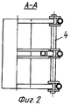
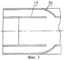
Сущность изобретения поясняется чертежом, где на фиг.1 изображен общий вид установки, на фиг.2 - сечение по опорным стойкам эстакады, на фиг.3 - вид сверху направляющего желоба, на фиг.4 - гидравлическая схема установки. The invention is illustrated by the drawing, in which Fig. 1 shows a general view of the installation, Fig. 2 is a cross-sectional view along the support posts of the flyover, Fig. 3 is a top view of the guide trough, and Fig. 4 is a hydraulic diagram of the installation.
Установка (фиг.1) состоит из закрытой эстакады 1 с опорными стойками 2, понтонов 3 со стержнями, шарнирно присоединенных к опорным стойкам 2 посредством валов 4 (фиг.2), удлинителей 5 со штоками 6, масляных насосов 7, подвешенных к стойкам 8 на эстакаде, качалки 9 с лопастями на опоре 10, масляного насоса 11, присоединенного к стойке 12 на эстакаде, направляющего желоба 13 с основанием 14, направляющими стенками 15 и дополнительными дуговыми стенками 16 (фиг.3) при работе установки с масляными насосами двойного действия. Гидравлическое оборудование состоит из масляного бака 17 с фильтром, гидроаккумулятора 18, коллектора 19 с гидроклапанами 20, предохранительного клапана 21, запорной арматуры 22, манометра 23, маслопроводов: всасывающих 24, нагнетательных 25, отводных 26, сливного 27 (фиг.4). The installation (Fig. 1) consists of a closed flyover 1 with support posts 2, pontoons 3 with rods pivotally attached to the support posts 2 by means of shafts 4 (Fig. 2), extension cords 5 with rods 6, oil pumps 7 suspended from the posts 8 on the viaduct, rocking chair 9 with blades on the support 10, an
Установка работает следующим образом. Installation works as follows.
При прохождении волн и во время приливов понтоны 3 и качалка 9 приводят в работу масляные насосы 7, 11, нагнетающие масло из масляного бака 17 в гидроаккумулятор 18, из которого масло поступает в коллектор 19 с гидроклапанами 20, настроенными на различные перепады давления с целью последовательного автоматического отключения и подключения части потребителей масла для поддержания стабильного давления в гидроаккумуляторе 18 при изменениях усилий действия морских волн и приливов. При использовании в установке масляных насосов двойного действия направляющий желоб 13 выполнен с дополнительными дуговыми стенками 16, обеспечивающими дополнительный приток воды прилива на качалку во время отлива. During the passage of waves and during high tides, the pontoons 3 and the rocking chair 9 operate the
Таким образом, данная установка может быть использована в качестве привода электрогенераторов и других механизмов, при этом гидроприводы подключаются к гидроклапанам 20 коллектора 19, а слив масла производится в масляный бак 17. Thus, this installation can be used as a drive for electric generators and other mechanisms, while the hydraulic actuators are connected to the
Экономический эффект данной установки заключается в использовании энергии морских волн и приливов взамен других дорогостоящих источников энергии для привода электрогенераторов и различных механизмов с помощью гидроприводов. The economic effect of this installation is to use the energy of sea waves and tides instead of other expensive sources of energy to drive electric generators and various mechanisms using hydraulic drives.
Источники информации
1. Патент N 2139440, МКИ F 03 B, Бюл. N 28, 10.10.99 (прототип).Sources of information
1. Patent N 2139440, MKI F 03 B, Bull. N 28, 10.10.99 (prototype).
2. Авторские свидетельства N 868095, МКИ F 03 B, 16.04.79, N 1100418, МКИ F 03 B, 23.02.83. 2. Copyright certificates N 868095, MKI F 03 B, 04.16.79, N 1100418, MKI F 03 B, 02.23.83.
Claims (1)
Priority Applications (1)
| Application Number | Priority Date | Filing Date | Title |
|---|---|---|---|
| RU2000130044/06A RU2198317C2 (en) | 2000-12-01 | 2000-12-01 | Marine power plant |
Applications Claiming Priority (1)
| Application Number | Priority Date | Filing Date | Title |
|---|---|---|---|
| RU2000130044/06A RU2198317C2 (en) | 2000-12-01 | 2000-12-01 | Marine power plant |
Publications (2)
| Publication Number | Publication Date |
|---|---|
| RU2000130044A RU2000130044A (en) | 2002-11-20 |
| RU2198317C2 true RU2198317C2 (en) | 2003-02-10 |
Family
ID=20242807
Family Applications (1)
| Application Number | Title | Priority Date | Filing Date |
|---|---|---|---|
| RU2000130044/06A RU2198317C2 (en) | 2000-12-01 | 2000-12-01 | Marine power plant |
Country Status (1)
| Country | Link |
|---|---|
| RU (1) | RU2198317C2 (en) |
Cited By (3)
| Publication number | Priority date | Publication date | Assignee | Title |
|---|---|---|---|---|
| CN102384017A (en) * | 2011-09-29 | 2012-03-21 | 青岛经济技术开发区泰合海浪能研究中心 | Vertical shaft waterflow generating system |
| CN105041560A (en) * | 2015-05-29 | 2015-11-11 | 邓允河 | Power generating method utilizing ocean current energy |
| CN111051690A (en) * | 2018-08-02 | 2020-04-21 | 国立大学法人东京大学 | Wave power generation system |
Citations (5)
| Publication number | Priority date | Publication date | Assignee | Title |
|---|---|---|---|---|
| DE2629246A1 (en) * | 1975-01-07 | 1978-01-05 | Martin Gunnar Loewgren | DEVICE FOR GENERATING ENERGY BY EXPLOITING THE MOVEMENTS OF WATERWAVES |
| US4132901A (en) * | 1975-08-07 | 1979-01-02 | Don Crausbay | Electric power generating system |
| GB1560499A (en) * | 1976-11-20 | 1980-02-06 | Hook C R | Apparatus for extracting energy from waves |
| US4480966A (en) * | 1981-07-29 | 1984-11-06 | Octopus Systems, Inc. | Apparatus for converting the surface motion of a liquid body into usable power |
| RU2139440C1 (en) * | 1996-05-24 | 1999-10-10 | Предприятие по добыче и транспортировке природного газа "Надымгазпром" Российского акционерного общества "Газпром" | Energy converter |
-
2000
- 2000-12-01 RU RU2000130044/06A patent/RU2198317C2/en active
Patent Citations (5)
| Publication number | Priority date | Publication date | Assignee | Title |
|---|---|---|---|---|
| DE2629246A1 (en) * | 1975-01-07 | 1978-01-05 | Martin Gunnar Loewgren | DEVICE FOR GENERATING ENERGY BY EXPLOITING THE MOVEMENTS OF WATERWAVES |
| US4132901A (en) * | 1975-08-07 | 1979-01-02 | Don Crausbay | Electric power generating system |
| GB1560499A (en) * | 1976-11-20 | 1980-02-06 | Hook C R | Apparatus for extracting energy from waves |
| US4480966A (en) * | 1981-07-29 | 1984-11-06 | Octopus Systems, Inc. | Apparatus for converting the surface motion of a liquid body into usable power |
| RU2139440C1 (en) * | 1996-05-24 | 1999-10-10 | Предприятие по добыче и транспортировке природного газа "Надымгазпром" Российского акционерного общества "Газпром" | Energy converter |
Cited By (6)
| Publication number | Priority date | Publication date | Assignee | Title |
|---|---|---|---|---|
| CN102384017A (en) * | 2011-09-29 | 2012-03-21 | 青岛经济技术开发区泰合海浪能研究中心 | Vertical shaft waterflow generating system |
| CN102384017B (en) * | 2011-09-29 | 2013-06-12 | 青岛经济技术开发区泰合海浪能研究中心 | Vertical shaft waterflow generating system |
| CN105041560A (en) * | 2015-05-29 | 2015-11-11 | 邓允河 | Power generating method utilizing ocean current energy |
| CN105041560B (en) * | 2015-05-29 | 2017-08-29 | 广州雅图新能源科技有限公司 | A kind of electricity-generating method of utilization ocean current energy |
| CN111051690A (en) * | 2018-08-02 | 2020-04-21 | 国立大学法人东京大学 | Wave power generation system |
| CN111051690B (en) * | 2018-08-02 | 2021-04-27 | 国立大学法人东京大学 | wave power generation system |
Similar Documents
| Publication | Publication Date | Title |
|---|---|---|
| US4698969A (en) | Wave power converter | |
| US4742241A (en) | Wave energy engine | |
| KR101354182B1 (en) | Apparatus for generating electricity using tidal or current flow | |
| AU2006226179B2 (en) | Apparatus and control system for generating power from wave energy | |
| US20120032444A1 (en) | Wave Catcher | |
| RU2347937C1 (en) | Damless hydroelectric station | |
| WO2010076617A4 (en) | Method and apparatus for converting ocean wave energy into electricity | |
| CN108603481A (en) | Wide wave spectrum wave energy recovery device | |
| CN1069119C (en) | Sea wave power generator | |
| RU2198317C2 (en) | Marine power plant | |
| Sundar et al. | Conceptual design of OWC wave energy converters combined with breakwater structures | |
| ES2356719T3 (en) | UNDIMOTRIC POWER PLANT TO GENERATE ELECTRICITY. | |
| CN1800629A (en) | Electricity generating device by using ocean wave energy | |
| CN201215062Y (en) | Hydraulic generating system utilizing buoyance | |
| CN101705903B (en) | Impeller-type sea wave power generation device | |
| GB2443195A (en) | Power generation from water flow using jet pump principle | |
| CA2408855A1 (en) | Ocean wave energy converter | |
| SU1765485A1 (en) | Wave floating hydroelectric power station | |
| GB2472055A (en) | Dual bellows pneumatic wave energy device | |
| WO2006053843A1 (en) | Apparatus for converting energy from the wave motion of the sea | |
| RU2000130044A (en) | MARINE POWER INSTALLATION | |
| KR101239053B1 (en) | Ocean energy generation system | |
| JPH0429088Y2 (en) | ||
| RU59744U1 (en) | WAVE POWER INSTALLATION | |
| RU2183287C2 (en) | Power complex |