RU2196309C2 - Method determining torque - Google Patents
Method determining torque Download PDFInfo
- Publication number
- RU2196309C2 RU2196309C2 RU2000110472/28A RU2000110472A RU2196309C2 RU 2196309 C2 RU2196309 C2 RU 2196309C2 RU 2000110472/28 A RU2000110472/28 A RU 2000110472/28A RU 2000110472 A RU2000110472 A RU 2000110472A RU 2196309 C2 RU2196309 C2 RU 2196309C2
- Authority
- RU
- Russia
- Prior art keywords
- shaft
- frequency
- torque
- signals
- length
- Prior art date
Links
Images
Landscapes
- Measurement Of Mechanical Vibrations Or Ultrasonic Waves (AREA)
Abstract
Description
Изобретение относится к силоизмерительной технике и может быть использовано для измерения крутящего момента, передаваемого вращающимися валами различных объектов. The invention relates to load measuring technique and can be used to measure the torque transmitted by the rotating shafts of various objects.
Известен широкий спектр методов измерения крутящего момента, основанного на индуктивном, тензометрическом, магнитоупругом, фазометрическом, фотометрическом и ином комбинированном преобразовании крутящего момента в электрический сигнал (см., например, обзор Парфенова М.М. и Пчелинцевой В.Н. Современное состояние и перспективы развития преобразователей крутящего момента. М., ЦНИИТЭИ приборостроения, 1980). A wide range of methods for measuring torque is known, based on inductive, tensometric, magnetoelastic, phase, photometric and other combined conversion of torque into an electrical signal (see, for example, a review by M. M. Parfenov and V. N. Pchelintseva. Current status and prospects development of torque converters. M., TsNIITEI instrument making, 1980).
Общим недостатком указанных способов измерения крутящего момента является их низкая универсальность, обусловленная разнообразием конструкций и режимов работы объектов техники. A common drawback of these methods of measuring torque is their low versatility, due to the variety of designs and modes of operation of objects of technology.
Известен, в частности, фазометрический метод измерения крутящего момента, заключающийся в фотоэлектрическом формировании двух сигналов, сдвинутых по фазе на величину угла закручивания, и определении крутящего момента по величине разности фаз напряжений двух фототранзисторов, получающих световые импульсы от светодиодов через прорези растровых дисков (см. авт. св. СССР 1509640, G 01 L 3/04, 3/12, 1989). In particular, the phase-metric method for measuring torque is known, which consists in the photoelectric formation of two signals that are phase-shifted by the value of the twist angle, and determining the torque by the magnitude of the phase difference of the voltage of two phototransistors receiving light pulses from the LEDs through the slots of the raster disks (see ed. St. USSR 1509640, G 01 L 3/04, 3/12, 1989).
В дополнение к общему недостатку приведенных в качестве аналогов методов измерения крутящего момента: низкой универсальности, данный метод обладает зауженным диапазоном измерения крутящего момента (большой величиной малых крутящих моментов). In addition to the general drawback of torque measurement methods cited as analogues: low versatility, this method has a narrowed range of torque measurement (a large value of small torques).
Наиболее близким по технической сущности к заявляемому способу является способ определения крутящего момента путем регистрации с помощью разнесенных датчиков двух периодических параметров, связанных с силовым режимом вращения вала и представляющих собой один из параметров рабочего цикла двигателя, например давление топлива у форсунки какого-либо цилиндра, и вибрацию на опоре вала двигателя, формирования на их основе сигналов, имеющих друг относительно друга фазовый сдвиг, в частности двух импульсных сигналов, и после их измерительной обработки, а именно получения с помощью измерителя временных интервалов величины фазового сдвига, вычисления величины крутящего момента (см. а.с. СССР 1583765, G 01 L 3/10, 1990). The closest in technical essence to the claimed method is a method for determining the torque by registering with the help of spaced sensors two periodic parameters associated with the power mode of rotation of the shaft and representing one of the parameters of the engine’s duty cycle, for example, the fuel pressure at the nozzle of any cylinder, and vibration on the motor shaft support, the formation on their basis of signals having a phase shift relative to each other, in particular two pulse signals, and after their measurement processing, namely receiving via time slots meter magnitude of the phase shift, compute a torque value (see. AS USSR 1583765, G 01 L 3/10, 1990).
Недостатками этого способа являются сниженные надежность и точность измерения, связанные с ухудшением помехоустойчивости. The disadvantages of this method are the reduced reliability and measurement accuracy associated with the deterioration of noise immunity.
Технический результат заявляемого способа - расширение области применения за счет повышения универсальности метода измерения и упрощения его эксплуатационных свойств, а также повышение надежности и точности измерения. The technical result of the proposed method is the expansion of the scope by increasing the versatility of the measurement method and simplifying its operational properties, as well as improving the reliability and accuracy of the measurement.
Указанный технический результат достигается тем, что в способе определения крутящего момента путем регистрации с помощью разнесенных датчиков двух периодических параметров, связанных с силовым режимом вращения вала, формирования на их основе сигналов, имеющих друг относительно друга фазовый сдвиг, и после их измерительной обработки вычисления величины крутящего момента, в качестве обоих периодических параметров используют частоту вращения вала, которую синхронно регистрируют с разнесением датчиков частоты на длину измерительного участка вала и преобразуют в два частотно-модулированных сигнала до выделения их разностной частоты биений, а крутящий момент определяют по формуле:
Mкр = KΔφ•Kв•Fб,
где Fб - частота биений, Гц;
KΔφ - частотный коэффициент закручивания вала,
![]()
где Fд - девиация частоты, Гц,
Кв - опорный коэффициент данного типа вала,
![]()
где G - модуль сдвига материала вала, н/м2,
Jp - полярный момент инерции сечения вала, м4,
L - длина измерительного участка вала, м.The specified technical result is achieved by the fact that in the method for determining the torque by registering with the help of spaced sensors two periodic parameters associated with the power mode of rotation of the shaft, generating signals based on them having a phase shift relative to each other, and after measuring the calculation of the magnitude of the torque moment, as both periodic parameters use the shaft speed, which is synchronously recorded with the frequency sensors spaced by the length of the measuring part of the shaft and convert into two frequency-modulated signals until their differential beat frequency is allocated, and the torque is determined by the formula:
M cr = K Δφ • K in • F b ,
where F b - beat frequency, Hz;
K Δφ is the frequency coefficient of twisting of the shaft,
![]()
where F d is the frequency deviation, Hz,
K in - the reference coefficient of this type of shaft,
![]()
where G is the shear modulus of the shaft material, n / m 2 ,
J p - polar moment of inertia of the shaft section, m 4 ,
L is the length of the measuring section of the shaft, m
Предлагаемый способ основан на вытекающем из возможностей частотно-модуляционного метода измерения выведении пропорциональности между угловыми характеристиками деформации кручения и разностной частотой биений
![]()
где Δφ - угол закручивания вала,
φ = 2π - полный угол поворота вала.The proposed method is based on the derivation of the proportionality between the angular characteristics of torsional deformation and the difference frequency of the beats resulting from the capabilities of the frequency-modulation measurement method
![]()
where Δφ is the angle of rotation of the shaft,
φ = 2π is the total angle of rotation of the shaft.
Указанная зависимость получена в результате введения дискретизации по координате и времени для прямых упругих стержней и валов при рассмотрении их продольных и крутильных колебаний (см. книгу Маквецкого Е.Н. и Тарковского А. М. Механические воздействия и защита радиоэлектронной аппаратуры. М., "Радио и связь", 1993, с.64; 72-74, выражения 4.25-4.28; с.78-80) и последующей, применительно к условиям деформации кручения (сдвига), ее адаптации и ее взаимосвязи через временную составляющую с известным в радиолокации в частотном методе измерения дальности соотношением между частотой биений и временем задержки:
Fб=2Fд•Fм•tз,
где Fм - частота модуляции, равная частоте вращения вала,
tз - время задержки, временной сдвиг двух периодических параметров друг относительно друга,
(см. книгу Финкельштейна М.И. Основы радиолокации, М., "Радио и связь", 1983, с.113, формула 2.8.2).The indicated dependence was obtained by introducing discretization by coordinate and time for straight elastic rods and shafts when considering their longitudinal and torsional vibrations (see the book by E. N. Makvetsky and A. M. Tarkovsky) Mechanical effects and protection of electronic equipment. M., " Radio and communication ", 1993, p.64; 72-74, expressions 4.25-4.28; p.78-80) and the following, in relation to the conditions of torsion deformation (shift), its adaptation and its relationship through the time component with the known in radar in the frequency measurement method Ocean between beat frequency and a delay time:
F b = 2F d • F m • t s ,
where F m is the modulation frequency equal to the rotational speed of the shaft,
t s - the delay time, the time shift of two periodic parameters relative to each other,
(see the book by M. M. Finkelstein, Fundamentals of Radar, M., "Radio and Communications", 1983, p.113, formula 2.8.2).
Из этого соотношения вытекает зависимость между угловыми характеристиками деформации кручения и разностной частотой биений. This relationship implies the relationship between the angular characteristics of torsion strain and the difference frequency of the beats.
Действительно, при разностной частоте биений
Fб=2Fд•Fм•tз,
имеет место равенство:
![]()
которое после перемножения и деления правой его части на 2π приходит к искомой зависимости:
![]()
где ![]()
F b = 2F d • F m • t s ,
the equality holds:
![]()
which, after multiplying and dividing its right-hand side by 2π, comes to the desired dependence:
![]()
Where ![]()
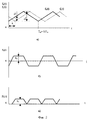
На фиг. 1 изображена структурная схема устройства для реализации предлагаемого способа; на фиг.2 - временные диаграммы электрических сигналов. In FIG. 1 shows a structural diagram of a device for implementing the proposed method; figure 2 - timing diagrams of electrical signals.
Устройство для реализации предлагаемого способа содержит датчики 1 и 2 частоты вращения вала, установленные на границах измерительного участка вала и выходами соединенные через триггеры Шмитта 3 и 4 и делители частоты 5 и 6 с входами интеграторов 7 и 8, снабженных, в свою очередь, на выходе усилителями напряжения 9 и 10, соединенными с модуляционными входами генераторов качающейся частоты 11 и 12. Последние своими выходами соединены с входами смесителя 13, на выходе снабженного фильтром низкой частоты 14, соединенного, в свою очередь, с входом вычислителя 15, снабженного на выходе цифровым индикатором 16. A device for implementing the proposed method contains
Предлагаемый способ реализуют следующим образом. The proposed method is implemented as follows.
С помощью разнесенных вдоль вала фотоэлектрических (или индуктивных) датчиков 1 и 2 частоты вращения вала (см. фиг.1) синхронно снимают с вращающегося вала два сдвинутых по фазе друг относительно друга сигнала с частотой, пропорциональной частоте вращения вала. With the help of photoelectric (or inductive)
Прошедшие через триггеры Шмитта 3 и 4 и делители частоты 5 и 6 подготовленные сигналы подают на интеграторы 7 и 8, с которых снимают сигналы в пилообразном виде, с треугольной формой, и пропускают их через усилители напряжения 9 и 10 на генераторы качающейся частоты 11 и 12 для обеспечения периодической частотной модуляции и сохранившие фазовый сдвиг, сформированные частотно-модулированные сигналы, а именно, опорный сигнал (с датчика 1) с частотой f0(t) и сдвинутый сигнал (с датчика 2) с частотой fс(t) (см. фиг. 2а), подают на смеситель 13.Passed through Schmitt triggers 3 and 4 and
В результате смешения (сложения) двух частотно-модулированных сигналов на входе смесителя образуются биения. Мгновенная частота биений равна абсолютному значению разности мгновенных значений частот сдвинутых друг относительно друга частотно-модулированных сигналов |Fб(t)| = |f0(t)-fc(t)|, где f0(t) - мгновенное значение частоты опорного сигнала; fc(t) - мгновенное значение частоты сдвинутого сигнала (см. фиг.2,б,в). После детектирования в смесителе фильтром низкой частоты 14 выделяют преобразованный сигнал, имеющий частоту биений Fб.As a result of mixing (addition) of two frequency-modulated signals, beats are formed at the input of the mixer. The instantaneous beat frequency is equal to the absolute value of the difference between the instantaneous values of the frequencies of the frequency-modulated signals shifted relative to each other | F b (t) | = | f 0 (t) -f c (t) |, where f 0 (t) is the instantaneous value of the frequency of the reference signal; f c (t) is the instantaneous value of the frequency of the shifted signal (see figure 2, b, c). After detection in the mixer by a low-pass filter 14, a converted signal having a beat frequency F b is isolated.
С помощью вычислителя 15 по указанной в настоящем описании формуле вычисляют величину крутящего момента, передаваемого вращающимся валом, Мкр, которую регистрируют с помощью цифрового индикатора 16.Using the calculator 15 according to the formula specified in the present description, the magnitude of the torque transmitted by the rotating shaft, M cr , which is recorded using the digital indicator 16, is calculated.
Claims (1)
Mкр = KΔφ•Kв•Fб,
где Fб - частота биений, Гц;
KΔφ - частотный коэффициент закручивания вала,
где Fд - девиация частоты, Гц;
Кв - опорный коэффициент данного типа вала,
где G - модуль сдвига материала вала, н/м2;
Jр - полярный момент инерции сечения вала, м4;
L - длина измерительного участка вала, м.The method of determining the torque by recording with the help of sensors spaced apart by the length of the measuring section of the shaft of the sensor two periodic parameters associated with the power mode of rotation of the shaft, generating based on them signals containing information about the twisting of the shaft, and evaluating the magnitude of the torque resulting from the computational processing of the latter, different the fact that as both periodic parameters use the shaft speed, on the basis of which form two frequency-modulated signals received s sensor signals previously converted into two baseband signal sawtooth form, e.g., a triangular shape, the inputs of the two oscillators oscillating frequency is mixed generated frequency-modulated signals to highlight their difference beat frequency at which the judged torque value determined by the formula
M cr = K Δφ • K in • F b ,
where F b - beat frequency, Hz;
K Δφ is the frequency coefficient of twisting of the shaft,
where F d is the frequency deviation, Hz;
K in - the reference coefficient of this type of shaft,
where G is the shear modulus of the shaft material, n / m 2 ;
J p - polar moment of inertia of the shaft section, m 4 ;
L is the length of the measuring section of the shaft, m
Priority Applications (1)
| Application Number | Priority Date | Filing Date | Title |
|---|---|---|---|
| RU2000110472/28A RU2196309C2 (en) | 2000-04-24 | 2000-04-24 | Method determining torque |
Applications Claiming Priority (1)
| Application Number | Priority Date | Filing Date | Title |
|---|---|---|---|
| RU2000110472/28A RU2196309C2 (en) | 2000-04-24 | 2000-04-24 | Method determining torque |
Publications (2)
| Publication Number | Publication Date |
|---|---|
| RU2000110472A RU2000110472A (en) | 2002-03-10 |
| RU2196309C2 true RU2196309C2 (en) | 2003-01-10 |
Family
ID=20233861
Family Applications (1)
| Application Number | Title | Priority Date | Filing Date |
|---|---|---|---|
| RU2000110472/28A RU2196309C2 (en) | 2000-04-24 | 2000-04-24 | Method determining torque |
Country Status (1)
| Country | Link |
|---|---|
| RU (1) | RU2196309C2 (en) |
Cited By (1)
| Publication number | Priority date | Publication date | Assignee | Title |
|---|---|---|---|---|
| RU2684444C1 (en) * | 2018-06-14 | 2019-04-09 | федеральное государственное бюджетное образовательное учреждение высшего образования "Волгоградский государственный аграрный университет" (ФГБОУ ВО Волгоградский ГАУ) | Method of determining the torque on rotating shaft |
-
2000
- 2000-04-24 RU RU2000110472/28A patent/RU2196309C2/en not_active IP Right Cessation
Non-Patent Citations (1)
| Title |
|---|
| ОДИНЕЦ С.С., ТОПИЛИН Г.Е. Средства измерения крутящего момента. - М.: Машиностроение, 1977, с.48-59. * |
Cited By (1)
| Publication number | Priority date | Publication date | Assignee | Title |
|---|---|---|---|---|
| RU2684444C1 (en) * | 2018-06-14 | 2019-04-09 | федеральное государственное бюджетное образовательное учреждение высшего образования "Волгоградский государственный аграрный университет" (ФГБОУ ВО Волгоградский ГАУ) | Method of determining the torque on rotating shaft |
Similar Documents
| Publication | Publication Date | Title |
|---|---|---|
| US4809703A (en) | Ultrasonic doppler blood flow meter | |
| RU2196309C2 (en) | Method determining torque | |
| RU2161773C2 (en) | Angle determination device | |
| JPS6152950B2 (en) | ||
| CN2570740Y (en) | Subdivision-assembly magnetoelectric/photoelectric digital integrated measuring apparatus for shafting torque and torsion | |
| SU693536A1 (en) | Reference signal generator | |
| SU724953A1 (en) | Method of determining unbalance phase of rotors | |
| SU685982A1 (en) | Method of measuring parameters of shaft rotation | |
| SU502250A1 (en) | Phase dynamometer for measuring torque and power | |
| SU775638A1 (en) | Device for determining mechanical characteristic rigidity of executive motor | |
| SU1317323A1 (en) | Elastoviscometer | |
| SU756231A1 (en) | Piezoelectric force transducer | |
| SU564548A1 (en) | String balancing displacement pick-up | |
| RU2123672C1 (en) | Force measuring device | |
| SU887952A1 (en) | Method of determining dynamic coefficient of shaft torque | |
| JPH0127067Y2 (en) | ||
| SU283042A1 (en) | METHOD FOR DETERMINING SIZE AND SIGN OF BALANCE OF CAMERTON | |
| WO2021130970A1 (en) | Viscoelasticity measurement method and viscoelasticity measurement device | |
| JPH023930B2 (en) | ||
| SU939956A1 (en) | Ultrasound vibration meter | |
| RU2017097C1 (en) | Method of determination of axial force and torque | |
| JPH067132B2 (en) | Ultrasonic velocity measuring device, ultrasonic sonic velocity measuring device and ultrasonic velocity / flow direction / sonic velocity measuring device | |
| SU711587A1 (en) | Functional angle-of-rotation converter | |
| SU794532A1 (en) | Ultrasonic liquid rate meter | |
| Lin et al. | Development of wireless torque sensing using embedded microchip |
Legal Events
| Date | Code | Title | Description |
|---|---|---|---|
| MM4A | The patent is invalid due to non-payment of fees |
Effective date: 20040425 |