RU2191479C2 - Method and device for transmitting access channel preamble in mobile communication system - Google Patents
Method and device for transmitting access channel preamble in mobile communication system Download PDFInfo
- Publication number
- RU2191479C2 RU2191479C2 RU2000109575A RU2000109575A RU2191479C2 RU 2191479 C2 RU2191479 C2 RU 2191479C2 RU 2000109575 A RU2000109575 A RU 2000109575A RU 2000109575 A RU2000109575 A RU 2000109575A RU 2191479 C2 RU2191479 C2 RU 2191479C2
- Authority
- RU
- Russia
- Prior art keywords
- preamble
- interval
- mobile station
- signal
- transmission
- Prior art date
Links
- 238000000034 method Methods 0.000 title claims abstract description 43
- 238000010295 mobile communication Methods 0.000 title abstract description 8
- 230000005540 biological transmission Effects 0.000 claims abstract description 103
- 230000008054 signal transmission Effects 0.000 claims abstract 3
- 230000015572 biosynthetic process Effects 0.000 claims 1
- 230000000694 effects Effects 0.000 abstract description 2
- 239000000126 substance Substances 0.000 abstract 1
- 238000004891 communication Methods 0.000 description 18
- 238000010586 diagram Methods 0.000 description 16
- 238000001514 detection method Methods 0.000 description 14
- 239000002775 capsule Substances 0.000 description 10
- 230000011664 signaling Effects 0.000 description 10
- 238000002834 transmittance Methods 0.000 description 3
- 230000000007 visual effect Effects 0.000 description 3
- 241000394635 Acetomicrobium mobile Species 0.000 description 1
- 102100035460 Polynucleotide 5'-hydroxyl-kinase Human genes 0.000 description 1
- 230000015556 catabolic process Effects 0.000 description 1
- 238000006731 degradation reaction Methods 0.000 description 1
- 230000001934 delay Effects 0.000 description 1
- 230000000737 periodic effect Effects 0.000 description 1
- 238000004904 shortening Methods 0.000 description 1
- 230000001360 synchronised effect Effects 0.000 description 1
Images


Classifications
-
- H—ELECTRICITY
- H04—ELECTRIC COMMUNICATION TECHNIQUE
- H04B—TRANSMISSION
- H04B7/00—Radio transmission systems, i.e. using radiation field
- H04B7/24—Radio transmission systems, i.e. using radiation field for communication between two or more posts
- H04B7/26—Radio transmission systems, i.e. using radiation field for communication between two or more posts at least one of which is mobile
- H04B7/2662—Arrangements for Wireless System Synchronisation
- H04B7/2668—Arrangements for Wireless Code-Division Multiple Access [CDMA] System Synchronisation
-
- H—ELECTRICITY
- H04—ELECTRIC COMMUNICATION TECHNIQUE
- H04B—TRANSMISSION
- H04B7/00—Radio transmission systems, i.e. using radiation field
- H04B7/24—Radio transmission systems, i.e. using radiation field for communication between two or more posts
- H04B7/26—Radio transmission systems, i.e. using radiation field for communication between two or more posts at least one of which is mobile
-
- H—ELECTRICITY
- H04—ELECTRIC COMMUNICATION TECHNIQUE
- H04L—TRANSMISSION OF DIGITAL INFORMATION, e.g. TELEGRAPHIC COMMUNICATION
- H04L7/00—Arrangements for synchronising receiver with transmitter
- H04L7/04—Speed or phase control by synchronisation signals
- H04L7/041—Speed or phase control by synchronisation signals using special codes as synchronising signal
-
- H—ELECTRICITY
- H04—ELECTRIC COMMUNICATION TECHNIQUE
- H04W—WIRELESS COMMUNICATION NETWORKS
- H04W74/00—Wireless channel access
- H04W74/08—Non-scheduled access, e.g. ALOHA
- H04W74/0866—Non-scheduled access, e.g. ALOHA using a dedicated channel for access
- H04W74/0891—Non-scheduled access, e.g. ALOHA using a dedicated channel for access for synchronized access
-
- H—ELECTRICITY
- H04—ELECTRIC COMMUNICATION TECHNIQUE
- H04B—TRANSMISSION
- H04B1/00—Details of transmission systems, not covered by a single one of groups H04B3/00 - H04B13/00; Details of transmission systems not characterised by the medium used for transmission
- H04B1/69—Spread spectrum techniques
- H04B1/707—Spread spectrum techniques using direct sequence modulation
- H04B1/7073—Synchronisation aspects
- H04B1/7075—Synchronisation aspects with code phase acquisition
-
- H—ELECTRICITY
- H04—ELECTRIC COMMUNICATION TECHNIQUE
- H04B—TRANSMISSION
- H04B2201/00—Indexing scheme relating to details of transmission systems not covered by a single group of H04B3/00 - H04B13/00
- H04B2201/69—Orthogonal indexing scheme relating to spread spectrum techniques in general
- H04B2201/707—Orthogonal indexing scheme relating to spread spectrum techniques in general relating to direct sequence modulation
- H04B2201/70701—Orthogonal indexing scheme relating to spread spectrum techniques in general relating to direct sequence modulation featuring pilot assisted reception
-
- H—ELECTRICITY
- H04—ELECTRIC COMMUNICATION TECHNIQUE
- H04B—TRANSMISSION
- H04B2201/00—Indexing scheme relating to details of transmission systems not covered by a single group of H04B3/00 - H04B13/00
- H04B2201/69—Orthogonal indexing scheme relating to spread spectrum techniques in general
- H04B2201/707—Orthogonal indexing scheme relating to spread spectrum techniques in general relating to direct sequence modulation
- H04B2201/7097—Direct sequence modulation interference
- H04B2201/709709—Methods of preventing interference
-
- H—ELECTRICITY
- H04—ELECTRIC COMMUNICATION TECHNIQUE
- H04W—WIRELESS COMMUNICATION NETWORKS
- H04W74/00—Wireless channel access
-
- Y—GENERAL TAGGING OF NEW TECHNOLOGICAL DEVELOPMENTS; GENERAL TAGGING OF CROSS-SECTIONAL TECHNOLOGIES SPANNING OVER SEVERAL SECTIONS OF THE IPC; TECHNICAL SUBJECTS COVERED BY FORMER USPC CROSS-REFERENCE ART COLLECTIONS [XRACs] AND DIGESTS
- Y02—TECHNOLOGIES OR APPLICATIONS FOR MITIGATION OR ADAPTATION AGAINST CLIMATE CHANGE
- Y02D—CLIMATE CHANGE MITIGATION TECHNOLOGIES IN INFORMATION AND COMMUNICATION TECHNOLOGIES [ICT], I.E. INFORMATION AND COMMUNICATION TECHNOLOGIES AIMING AT THE REDUCTION OF THEIR OWN ENERGY USE
- Y02D30/00—Reducing energy consumption in communication networks
- Y02D30/70—Reducing energy consumption in communication networks in wireless communication networks
Landscapes
- Engineering & Computer Science (AREA)
- Computer Networks & Wireless Communication (AREA)
- Signal Processing (AREA)
- Mobile Radio Communication Systems (AREA)
- Synchronisation In Digital Transmission Systems (AREA)
Abstract
Description
1. Область техники, к которой относится изобретение
Изобретение относится в основном к системам мобильной связи и, более конкретно касается способа передачи преамбулы канала доступа в системе мобильной связи множественного доступа с кодовым разделением каналов (МДКР).1. The technical field to which the invention relates.
The invention relates mainly to mobile communication systems and, more particularly, relates to a method for transmitting an access channel preamble in a code division multiple access (CDMA) mobile communication system.
Уровень техники
Используемый в настоящем описании термин "канал доступа" относится ко всем каналам, по которым осуществляется передача передающей стороной, выдающей запрос приемной стороне на установление связи для этих каналов. То есть термин "канал доступа" относится ко всем каналам, по которым перед передачей сообщения передается сигнал, известный как "преамбула". Использованный в настоящем описании термин "канал доступа" не ограничен каналом доступа в его общепринятом значении, применяемом в известных системах мобильной связи. Например, каналы доступа включают в себя обратный канал доступа (ОКД), обратный общий канал управления (ООКУ) и обратный выделенный (специализированный) канал доступа (ОВКД).State of the art
Used in the present description, the term "access channel" refers to all channels through which the transmitting side transmits a request to the receiving side to establish communication for these channels. That is, the term “access channel” refers to all channels through which a signal known as a “preamble” is transmitted before transmitting a message. Used in the present description, the term "access channel" is not limited to the access channel in its generally accepted meaning used in known mobile communication systems. For example, access channels include a reverse access channel (OKD), a reverse common control channel (OKOK), and a reverse dedicated (dedicated) access channel (OVKD).
Для безошибочного приема сигнала от передающей стороны приемная сторона должна быть синхронизирована с сигналом, пересылаемым от передающей стороны. Вхождение в синхронизм является весьма важным фактором, который определяет пропускную способность системы связи МДКР. For error-free reception of a signal from the transmitting side, the receiving side must be synchronized with the signal sent from the transmitting side. Entering synchronism is a very important factor that determines the throughput of a CDMA communication system.
В системе мобильной связи мобильная станция входит в синхронизм с сигналом, принимаемым от базовой станции, в соответствии с заданной процедурой вхождения в синхронизм, запускаемой с момента включения питания мобильной станции. Мобильная станция поддерживает синхронизацию посредством процедуры отслеживания синхросигналов, выполнение которой продолжается, пока не будет отключено питание мобильной станции, с тем, чтобы в любой момент времени можно было возобновить связь с базовой станцией. В процедуре вхождения в синхронизм, применяемой на мобильной станции, используется опорный сигнал в виде канала пилот-сигнала. Этот опорный сигнал передается на некоторую мобильную станцию, находящуюся в зоне соты, которая управляется базовой станцией. Базовая станция может передавать опорный сигнал непрерывно, пока система функционирует, поскольку опорный сигнал передается на некоторую, заранее неопределенную мобильную станцию. Так как этот опорный сигнал заранее оговорен в соответствии с определенным соглашением между базовой станцией и мобильной станцией, мобильная станция может всякий раз, когда включено питание, принимать сигналы от базовой станции путем отслеживания этого опорного сигнала и вхождения с ним в синхронизм. In a mobile communication system, a mobile station is in synchronism with a signal received from a base station in accordance with a predetermined synchronization entry procedure that starts from the moment the power of the mobile station is turned on. The mobile station maintains synchronization through a clock tracking procedure, which continues until the power of the mobile station is turned off so that communication with the base station can be resumed at any time. The synchronization procedure used at the mobile station uses a reference signal in the form of a pilot channel. This reference signal is transmitted to some mobile station located in the area of the cell, which is controlled by the base station. The base station can transmit the reference signal continuously while the system is operating, since the reference signal is transmitted to some predetermined mobile station. Since this reference signal is predetermined in accordance with a certain agreement between the base station and the mobile station, the mobile station can, whenever the power is turned on, receive signals from the base station by tracking this reference signal and entering synchronism with it.
В отличие от вышесказанного на базовой станции процедура вхождения в синхронизм в момент включения питания мобильной станции не запускается. Причина этого заключается в том, что мобильная станция запрещает передачу ненужных сигналов и устанавливает связь для передачи только в момент, когда появляется сообщение или данные, подлежащие передаче, что минимизирует энергопотребление на мобильной станции и уменьшает помехи на базовой станции. Эта процедура установления связи включает процедуру вхождения в синхронизм, посредством которой базовая станция входит в синхронизм с сигналом, принимаемым от мобильной станции. In contrast to the above, the base station does not start the synchronization procedure when the mobile station is turned on. The reason for this is that the mobile station prohibits the transmission of unnecessary signals and establishes communication for transmission only when a message or data to be transmitted appears, which minimizes power consumption at the mobile station and reduces interference at the base station. This communication establishment procedure includes a synchronization entry procedure whereby the base station enters into synchronism with a signal received from the mobile station.
Для эффективного вхождения в синхронизм мобильная станция передает преамбулу ПА, показанную на фиг.2, на базовую станцию в течение определенного временного интервала перед посылкой сообщения или данных. Используемый здесь термин "преамбула" относится к сигналу, заранее оговоренному между базовой станцией и мобильной станцией. В большинстве систем мобильной связи начало интервала передачи преамбулы определяется фиксированным системным параметром или может быть выбрано на мобильной станции на основе имеющегося времени передачи, определяемого визуальной информацией в системе. Здесь визуальную информацию получают из сигнала базовой станции, принимаемого после включения питания мобильной станции. Приемник на мобильной станции обнаруживает преамбулу в начале всех интервалов передачи преамбулы, оцениваемых исходя из визуальной информации системы, и входит в синхронизм. После обнаружения преамбулы базовая станция выполняет процедуры вхождения в синхронизм и отслеживания синхросигналов для приема сообщения, следующего за преамбулой. For effective synchronization, the mobile station transmits the PA preamble shown in FIG. 2 to the base station for a certain time interval before sending a message or data. As used herein, the term “preamble” refers to a signal previously agreed between a base station and a mobile station. In most mobile communication systems, the start of the preamble transmission interval is determined by a fixed system parameter or can be selected at the mobile station based on the available transmission time determined by the visual information in the system. Here, visual information is obtained from a base station signal received after turning on the power of the mobile station. The receiver at the mobile station detects the preamble at the beginning of all transmission intervals of the preamble, estimated based on the visual information of the system, and enters into synchronism. After detecting the preamble, the base station performs synchronization and tracking of clock signals to receive a message following the preamble.
На фиг.1 представлена схема передатчика канала доступа на мобильной станции в соответствии с известным уровнем техники. Figure 1 presents a diagram of a transmitter of an access channel at a mobile station in accordance with the prior art.
Обратимся к фиг.1, где генератор 120 преамбулы формирует преамбулу, которая показана под ссылочной позицией 210 на фиг.2. Усилитель 122 увеличивает мощность передачи для обратного канала пилот-сигнала (ОКПС) на интервале преамбулы, делая ее более высокой, чем мощность передачи для обратного канала пилот-сигнала на интервале сообщения канала доступа ("капсулы" сообщения). Селектор 124 используется для выбора интервала преамбулы и интервала передачи сообщения. Селектор 124 отбирает выходной сигнал усилителя 122 в начале интервала преамбулы и отбирает неусиленный сигнал в конце интервала преамбулы. Эта операция селектора 124 выполняется один раз для каждого канала доступа. Но в случае, если усилитель 122 преобразует коэффициент усиления со значением "Ку" на значение "1" на интервале преамбулы и интервале передачи сообщения, то избирательно использовать селектор 124 нет необходимости. То есть усилитель 122 устанавливает коэффициент усиления, равным "Ку" вначале интервала преамбулы, и устанавливает этот коэффициент, равным "1" в конце интервала преамбулы. Коэффициент усиления усилителя 122 устанавливается в течение одного интервала канала доступа только один раз. Смеситель 110 умножает ортогональные коды (+1, -1, +1, -1) на символ передачи для канала доступа с тем, чтобы отличать канал доступа от обратного канала. По каналу доступа на интервале преамбулы передача не происходит, а передача на базовую станцию выполняется с начала интервала капсулы сообщения, то есть после окончания интервала преамбулы. Усилитель 130 определяет отношение мощности передачи обратного канала пилот-сигнала к мощности передачи канала доступа на интервале капсулы сообщения. Комплексный расширитель 140 расширяет сигнал для обратного канала пилот-сигнала, сигнал для канала доступа и псевдошумовую синфазную (ПШС) и псевдошумовую квадратурную (ПШК) последовательности. Среди сигналов, расширяемых в комплексном расширителе 140, действительный сигнал подается в фильтр 150, а мнимый сигнал подается в фильтр 152. Фильтры 150 и 152 представляют собой фильтры, формирующие импульсы для сигнала передачи. Усилители 160 и 162 усиливают выходные сигналы фильтров 150 и 152 до уровня, который можно передавать через антенну. Смесители 170 и 172 умножают выходные сигналы усилителей 160 и 162 на сигнал несущей и преобразуют их в сигналы полосы радиочастот (РЧ). Преобразователь 180 фазы π/2 поддерживает разность фаз между сигналом несущей, умноженным на синфазный (С) канал, и сигналом несущей, умноженным на квадратурный (К) канал, равной 90o. Объединитель 190 объединяет выходные сигналы смесителей 170 и 172 и выводит объединенные сигналы на антенну.Referring to FIG. 1, where the
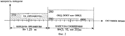
Теперь обратимся к фиг.2, где показан пример структуры сигнала, передаваемого по каналу доступа на мобильной станции в соответствии с известным уровнем техники. Now turn to figure 2, which shows an example of the structure of a signal transmitted over an access channel at a mobile station in accordance with the prior art.
Как представлено на фиг.2, мобильная станция передает преамбулу 210 на базовую станцию в течение определенного периода времени (например, N•1,25 мс) перед интервалом капсулы сообщения. Затем мобильная станция посылает сигнал по обратному каналу пилот-сигнала с мощностью передачи, сниженной до уровня, показанного под ссылочной позицией 280. Преамбула и сигнал обратного канала пилот-сигнала могут формироваться идентичным генератором последовательностей или разными генераторами последовательностей. Обратный канал пилот-сигнала используется для оценки обратного канала связи или процедуры отслеживания синхросигналов и может включать в себя информацию о прямом пилот-сигнале. Причина, по которой преамбула 210 передается с более высокой мощностью передачи, чем для обратного канала пилот-сигнала, заключается в том, что это облегчает обнаружение преамбулы и вхождение в синхронизм на базовой станции. То есть более высокая мощность передачи преамбулы 210 используется для повышения вероятности обнаружения и уменьшения вероятности пропуска преамбулы и вероятности ложной аварийной сигнализации. Капсула 280 сообщения содержит сообщение обратного канала и данные, подлежащие передаче на базовую станцию. As shown in FIG. 2, the mobile station transmits the
Проблема, связанная с известным способом передачи по каналу доступа, состоит в том, что интервал передачи преамбулы относительно велик и преамбула передается с относительно высокой мощностью передачи, хотя сообщение, требующее передачи отсутствует, в результате чего возрастают помехи в обратном канале связи. Следовательно, имеется потребность в способе, минимизирующем помехи в обратных каналах связи, а также повышающем вероятность обнаружения преамбулы. A problem with the known method of transmitting over an access channel is that the transmission interval of the preamble is relatively long and the preamble is transmitted with relatively high transmit power, although there is no message requiring transmission, resulting in increased interference in the reverse communication channel. Therefore, there is a need for a method that minimizes interference in the reverse channels of communication, as well as increasing the likelihood of detecting a preamble.
Сущность изобретения
Целью настоящего изобретения является создание устройства и способа передачи преамбулы канала доступа в системе связи МДКР, где мобильная станция передает преамбулу на базовую станцию с перерывами, уменьшая тем самым помехи в обратных каналах связи и энергопотребление.SUMMARY OF THE INVENTION
An object of the present invention is to provide an apparatus and method for transmitting an access channel preamble in a CDMA communication system, where the mobile station transmits the preamble to the base station intermittently, thereby reducing interference in the reverse communication channels and power consumption.
Другой целью настоящего изобретения является создание устройства и способа для передачи преамбулы канала доступа в системе связи МДКР, где передача преамбулы и сообщения канала доступа определяется в соответствии с тем, приняла ли мобильная станция информацию от базовой станции об обнаружении преамбулы, при прерывистой передаче преамбулы по каналу доступа. Another objective of the present invention is to provide a device and method for transmitting an access channel preamble in a CDMA communication system, where the transmission of the preamble and the access channel message is determined in accordance with whether the mobile station received information from the base station about the detection of the preamble during intermittent transmission of the preamble on the channel access.
Для достижения вышеуказанных целей настоящего изобретения устройство мобильной станции содержит генератор преамбулы для прерывистого формирования сигнала преамбулы, который передается в течение интервала преамбулы перед интервалом передачи сообщения обратного канала доступа, и передатчик для расширения и модуляции сигнала преамбулы, принимаемого от генератора преамбулы, и его передачи. To achieve the above objectives of the present invention, the mobile station device comprises a preamble generator for discontinuously generating a preamble signal that is transmitted during the preamble interval before the transmission interval of the reverse access channel message, and a transmitter for expanding and modulating the preamble signal received from the preamble generator and transmitting it.
Перечень чертежей
Вышеуказанные и другие цели, признаки и преимущества настоящего изобретения очевидны из нижеследующего подробного описания, приводимого со ссылками на сопроводительные чертежи, на которых одинаковыми ссылочными позициями обозначены одинаковые элементы и на которых:
фиг.1 представляет структурную схему передатчика канала доступа на мобильной станции согласно известному уровню техники;
фиг. 2 - диаграмма, иллюстрирующая передачу сигналов по каналу доступа в соответствии с известным уровнем техники;
фиг. 3 - структурная схема передатчика канала доступа на мобильной станции в соответствии с вариантом осуществления настоящего изобретения;
фиг. 4 - диаграмма, иллюстрирующая передачу сигналов по каналу доступа в соответствии с вариантом осуществления настоящего изобретения;
фиг. 5 - диаграмма, иллюстрирующая передачу сигналов по каналу доступа в соответствии с другим вариантом осуществления настоящего изобретения;
фиг. 6 - диаграмма, иллюстрирующая передачу сигналов по каналу доступа в соответствии с еще одним вариантом осуществления настоящего изобретения;
фиг. 7 - диаграмма, иллюстрирующая передачу сигналов по каналу доступа в соответствии с еще одним вариантом осуществления настоящего изобретения;
фиг. 8 - диаграмма, иллюстрирующая передачу сигналов по каналу доступа в соответствии с еще одним вариантом осуществления настоящего изобретения;
фиг. 9 - диаграмма, иллюстрирующая передачу сигналов по каналу доступа в соответствии с еще одним вариантом осуществления настоящего изобретения;
фиг.10 - диаграмма, иллюстрирующая передачу сигналов по каналу доступа в соответствии с еще одним вариантом осуществления настоящего изобретения;
фиг.11 - диаграмма, иллюстрирующая передачу сигналов по каналу доступа в соответствии с еще одним вариантом осуществления настоящего изобретения.List of drawings
The above and other objectives, features and advantages of the present invention are apparent from the following detailed description, given with reference to the accompanying drawings, in which the same reference numerals denote the same elements and in which:
figure 1 is a structural diagram of a transmitter of an access channel at a mobile station according to the prior art;
FIG. 2 is a diagram illustrating signaling on an access channel in accordance with the prior art;
FIG. 3 is a block diagram of an access channel transmitter at a mobile station in accordance with an embodiment of the present invention;
FIG. 4 is a diagram illustrating signaling on an access channel in accordance with an embodiment of the present invention;
FIG. 5 is a diagram illustrating signaling on an access channel in accordance with another embodiment of the present invention;
FIG. 6 is a diagram illustrating signaling on an access channel in accordance with yet another embodiment of the present invention;
FIG. 7 is a diagram illustrating signaling on an access channel in accordance with yet another embodiment of the present invention;
FIG. 8 is a diagram illustrating signaling on an access channel in accordance with yet another embodiment of the present invention;
FIG. 9 is a diagram illustrating signaling on an access channel in accordance with yet another embodiment of the present invention;
10 is a diagram illustrating signaling on an access channel in accordance with another embodiment of the present invention;
11 is a diagram illustrating signaling on an access channel in accordance with another embodiment of the present invention.
Подробное описание предпочтительного варианта осуществления изобретения
Настоящее изобретение предназначено для использования в системе мобильной связи МДКР. Предпочтительные варианты осуществления настоящего изобретения приведены лишь в качестве примеров и не ограничивают объем настоящего изобретения.Detailed Description of a Preferred Embodiment
The present invention is intended for use in a CDMA mobile communication system. Preferred embodiments of the present invention are given only as examples and do not limit the scope of the present invention.
В последующем описании одинаковые ссылочные позиции обозначают одинаковые компоненты, а известные функции или структуры подробно не описываются с тем, чтобы не затруднить понимание сущности изобретения ненужными подробностями. In the following description, like reference numerals indicate like components, and known functions or structures are not described in detail so as not to obscure the invention with unnecessary details.
На фиг.3 представлен передатчик канала доступа на мобильной станции согласно варианту осуществления настоящего изобретения. FIG. 3 illustrates an access channel transmitter in a mobile station according to an embodiment of the present invention.
Представленные на фиг.3 контроллер 326 передачи преамбулы и вентильный элемент 328 в генераторе 320 преамбулы используются для прерывистой передачи преамбулы. Параметры для этой процедуры пропускания задаются в виде системных параметров, в соответствии с которыми мобильная станция прерывисто передает преамбулу. Системные параметры могут включать в себя местоположение пропускания, длительность пропускания и период пропускания и т.п. На интервале преамбулы селектор 124 отбирает выходной сигнал усилителя 122, а контроллер 326 передачи преамбулы включает/выключает вентильный элемент 328 в соответствии с параметрами пропускания. Преамбула передается, когда вентильный элемент 328 включен, и наоборот преамбула не передается, когда вентильный элемент 328 выключен. Преамбула может передаваться с более высокой мощностью, чем мощность, которая используется в известном способе, где передача преамбулы не прерывается. Приращение мощности передачи может являться системным параметром, который суммируется с начальной мощностью передачи, причем этот параметр вычисляется системой с управлением мощности по разомкнутой петле. В конце интервала преамбулы и одновременно с началом интервала капсулы сообщения селектор 124 отбирает более низкий выходной сигнал усилителя 122 для того, чтобы выбрать обратный канал пилот-сигнала. Тем временем контроллер 326 передачи преамбулы поддерживает вентильный элемент 328 во включенном состоянии до окончания передачи по каналу доступа, давая возможность тем самым осуществлять непрерывную передачу обратного канала пилот-сигнала. 3, the
После передачи преамбулы на интервале преамбулы контроллер 326 передачи преамбулы управляет вентильным элементом 328 в соответствии с информацией об обнаружении преамбулы, полученной от базовой станции, и прерывает ставшую ненужной передачу преамбулы. Для минимизации задержки информации об обнаружении преамбулы базовая станция передает информацию об обнаружении преамбулы на мобильную станцию, не используя кодирование каналов либо используя кодирование каналов с минимальными задержками, к примеру блочное кодирование. Приняв от базовой станции информацию об обнаружении преамбулы, контроллер 326 передачи преамбулы на мобильной станции выдает управляющий сигнал на вентильный элемент 328, чтобы прервать передачу преамбулы, которая запланирована на остальной части интервала. Не приняв информацию об обнаружении преамбулы, контроллер 326 передачи преамбулы продолжает передавать преамбулу, как это запланировано на остальной части интервала, и проверяет, принимается ли информация об обнаружении преамбулы. Указанная процедура повторяется до конца интервала преамбулы. After transmitting the preamble on the preamble interval, the
Смеситель 110 умножает ортогональные коды (+1, -1, +1, -1) на символы передачи для канала доступа для того, чтобы отличить канал доступа от обратного канала связи. Передача по каналу доступа ведется с начала интервала капсулы сообщения, то есть по окончании интервала преамбулы, и прерывается на интервале преамбулы. Усилитель 130 определяет отношение мощности передачи обратного канала пилот-сигнала к мощности передачи канала доступа на интервале капсулы сообщения. Комплексный расширитель 140 принимает сигнал обратного канала пилот-сигнала, сигнал канала доступа и последовательности ПШс и ПШк для формирования комплексного расширенного сигнала. Среди сигналов, расширенных в комплексном расширителе 140, действительный сигнал подается в фильтр 150, а мнимый сигнал подается в фильтр 152. Фильтры 150 и 152 представляют собой фильтры, формирующие импульсы для сигнала передачи. Усилители 160 и 162 усиливают выходные сигналы фильтров 150 и 152 до уровня, который можно передавать через антенну. Смесители 170 и 172 умножают выходные сигналы усилителей 160 и 162 на сигнал несущей и преобразуют их в сигналы полосы РЧ. Преобразователь 180 фазы π/2 поддерживает разность фаз между сигналом несущей, умноженным на синфазный (С) канал, и сигналом несущей, умноженным на квадратурный (К) канал, равной 90o. Объединитель 190 объединяет выходные сигналы смесителей 170 и 172 и выводит объединенные сигналы на антенну.The
На фиг. 4-12 представлены примеры передачи сигналов по каналу доступа в соответствии с вариантами осуществления настоящего изобретения. In FIG. 4-12 illustrate examples of signaling on an access channel in accordance with embodiments of the present invention.
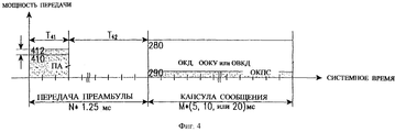
На фиг.4 представлена диаграмма для способа передачи сигнала преамбулы в первой части интервала преамбулы. Обратимся к фиг.4, где на всем интервале преамбулы (Т41+Т42) интервалом передачи преамбулы является интервал Т41, а интервалом, когда преамбула не передается, является интервал Т42. Преамбула передается с мощностью 412 передачи, которая выше обычной мощности 410 передачи преамбулы на величину ΔР. Предполагается, что структура интервала преамбулы такая же, как и в известном способе передачи преамбулы. Хотя здесь учитывается приращение мощности передачи ΔР, тем не менее, можно выделить для интервала преамбулы относительно низкую энергию путем регулирования отношения Т41 к Т42, что уменьшает помехи по обратным каналам связи. Базовая станция обнаруживает преамбулу в течение интервала, входящего в интервал передачи преамбулы Т41, на основе оценки временного интервала, в течение которого мобильная станция передает преамбулу. Обнаружение преамбулы выполняется с помощью коррелятора и согласованного фильтра, обычно используемых в известных системах. В случае использования коррелятора преамбула может быть обнаружена в реальном времени либо после сохранения в памяти сигналов, принятых в районе оцениваемого интервала Т41. 4 is a diagram for a method for transmitting a preamble signal in a first part of a preamble interval. Referring to FIG. 4, where, over the entire preamble interval (T41 + T42), the preamble transmission interval is the T41 interval, and the interval when the preamble is not transmitted is the T42 interval. The preamble is transmitted with transmit
На фиг.5 представлена диаграмма для способа передачи сигнала преамбулы в течение первой и последней частей интервала преамбулы. Обратимся к фиг.5, где во всем интервале преамбулы(Т51•2+Т52) интервалом передачи преамбулы является интервал Т51, а интервалом, когда преамбула не передается, является интервал Т52. После интервала передачи преамбулы Т51 и интервала Т52, когда преамбула не передается, преамбула передается снова в течение интервала Т51 непосредственно перед началом интервала капсулы сообщения. Преамбула передается с мощностью 512 (522) передачи, которая выше обычной мощности 510 (520) передачи преамбулы на величину ΔР. Предполагается, что структура интервала преамбулы такая же, как и в известном способе передачи преамбулы. Хотя здесь учитывается приращение мощности передачи ΔР, тем не менее, можно выделить для интервала преамбулы относительно низкую энергию путем регулирования отношения Т51 к Т52, что уменьшает помехи по обратным каналам связи. Базовая станция обнаруживает преамбулу в течение интервала, входящего в интервал передачи преамбулы Т51, на основе оценки временного интервала, в течение которого мобильная станция передает преамбулу. Обнаружение преамбулы и вхождение в синхронизм может быть обеспечено тем же способом, что был сформулирован выше со ссылками на фиг.4. 5 is a diagram for a method for transmitting a preamble signal during the first and last parts of a preamble interval. Referring to FIG. 5, where, over the entire preamble interval (T51 · 2 + T52), the preamble transmission interval is the T51 interval, and the interval when the preamble is not transmitted is the T52 interval. After the transmission interval of the T51 preamble and the T52 interval, when the preamble is not transmitted, the preamble is transmitted again during the T51 interval immediately before the start of the message capsule interval. The preamble is transmitted with a transmit power 512 (522), which is ΔP higher than the normal preamble transmit power 510 (520). It is assumed that the structure of the preamble interval is the same as in the known method for transmitting the preamble. Although the increment in transmit power ΔP is taken into account here, nevertheless, it is possible to isolate a relatively low energy for the preamble interval by adjusting the ratio of T51 to T52, which reduces interference on the reverse communication channels. The base station detects the preamble during an interval included in the transmission interval of the preamble T51, based on the estimated time interval during which the mobile station transmits the preamble. The detection of the preamble and entry into synchronism can be provided in the same way as was formulated above with reference to Fig.4.
На фиг.6 представлена диаграмма для способа периодической передачи преамбулы прерывистым образом. Обратимся к фиг.6, где в интервале преамбулы интервалом передачи преамбулы является интервал Т61, а интервалом, когда нет передачи преамбулы, является интервал Т62. Интервал передачи преамбулы Т61 и интервал Т62, когда преамбула не передается, периодически повторяются до конца интервала преамбулы. Преамбула может передаваться снова в течение интервала Т61 непосредственно перед началом интервала капсулы сообщения. Интервал преамбулы задается величиной (Т61+Т62)•N+T61 или (T61+T62)•N, где N - целое число, равное или большее нуля. Здесь мощность 612 (622, 632, 642) передачи для преамбулы выше, чем обычная мощность 610 (620, 630, 640) передачи преамбулы на величину ΔР. Предполагается, что структура интервала преамбулы такая же, как и в известном способе передачи преамбулы. Хотя здесь учитывается приращение мощности передачи ΔР, тем не менее, можно выделить для интервала преамбулы относительно низкую энергию путем регулирования отношения Т61 к Т62, что уменьшает помехи по обратным каналам связи. Базовая станция обнаруживает преамбулу в течение интервала, входящего в интервал передачи преамбулы Т61 на основе оценки временного интервала, в течение которого мобильная станция передает преамбулу. Обнаружение преамбулы и вхождение в синхронизм может быть обеспечено тем же способом, что сформулирован выше со ссылками на фиг.4. 6 is a diagram for a method for periodically transmitting a preamble in an intermittent manner. Referring to FIG. 6, in the preamble interval, the preamble transmission interval is the T61 interval, and the interval when there is no preamble transmission is the T62 interval. The transmission interval of the preamble T61 and the interval T62, when the preamble is not transmitted, are periodically repeated until the end of the preamble interval. The preamble may be transmitted again during the T61 interval immediately before the start of the message capsule interval. The preamble interval is specified by (T61 + T62) • N + T61 or (T61 + T62) • N, where N is an integer equal to or greater than zero. Here, the transmit power 612 (622, 632, 642) for the preamble is higher than the normal preamble transmit power 610 (620, 630, 640) by ΔP. It is assumed that the structure of the preamble interval is the same as in the known method for transmitting the preamble. Although the increment in transmit power ΔP is taken into account here, nevertheless, it is possible to allocate relatively low energy for the preamble interval by adjusting the ratio of T61 to T62, which reduces interference on the reverse communication channels. The base station detects the preamble during an interval included in the transmission interval of the preamble T61 based on the estimated time interval during which the mobile station transmits the preamble. The detection of the preamble and entry into synchronism can be provided in the same way as stated above with reference to figure 4.
В следующих двух способах в качестве расширенной концепции передачи преамбулы для всех каналов доступа, сформулированной выше, предлагается концепция обратной связи. In the following two methods, the feedback concept is proposed as an extended concept of preamble transmission for all access channels formulated above.
В первом способе базовая станция обнаруживает преамбулу и входит в синхронизм в системе, где интервал преамбулы является фиксированным. Базовая станция посылает на мобильную станцию информацию об обнаружении преамбулы и вхождении в синхронизм, чтобы предотвратить передачу мобильной станцией преамбулы на оставшейся части интервала преамбулы, коль скоро в этом нет необходимости. Не приняв от базовой станции информацию о вхождении в синхронизм, мобильная станция в течение интервала передачи преамбулы в оставшейся части интервала преамбулы передает преамбулу с мощностью передачи, увеличенной на заданный системный параметр. Если до конца интервала преамбулы отсутствует информация о вхождении в синхронизм, принимаемая от базовой станции, мобильная станция принимает решение о том, что на базовой станции вхождение в синхронизм не произошло, и не передает на базовую станцию сообщение канала доступа. In the first method, the base station detects the preamble and enters synchronism in a system where the preamble interval is fixed. The base station sends preamble detection and synchronization information to the mobile station to prevent the mobile station from transmitting the preamble for the remainder of the preamble interval, as long as this is not necessary. Having not received synchronization information from the base station, the mobile station transmits the preamble with the transmit power increased by a predetermined system parameter during the preamble transmission interval in the remaining part of the preamble interval. If, prior to the end of the preamble interval, there is no synchronization information received from the base station, the mobile station decides that no synchronization has occurred at the base station and does not transmit the access channel message to the base station.
Во втором способе базовая станция обнаруживает преамбулу и входит в синхронизм в системе, где интервал преамбулы является переменной величиной. Приняв от базовой станции информацию о вхождении в синхронизм, мобильная станция укорачивает интервал преамбулы и передает на базовую станцию сообщение канала доступа. В системе, где интервал преамбулы является переменным, максимальный интервал преамбулы определяется системным параметром. Не приняв информацию о вхождении в синхронизм на интервале преамбулы, заданном системным параметром, мобильная станция передает на базовую станцию преамбулу с мощностью, увеличенной на системный параметр, в течение интервала передачи преамбулы в оставшейся части интервала преамбулы. Если до конца интервала преамбулы отсутствует информация о вхождении в синхронизм, принимаемая от базовой станции, мобильная станция принимает решение о том, что на базовой станции вхождение в синхронизм не произошло, и не передает на базовую станцию сообщение канала доступа. In the second method, the base station detects the preamble and enters synchronism in the system, where the preamble interval is a variable. Having received information about the entry into synchronism from the base station, the mobile station shortens the preamble interval and transmits an access channel message to the base station. In a system where the preamble interval is variable, the maximum preamble interval is determined by the system parameter. Having not received the synchronization information on the preamble interval specified by the system parameter, the mobile station transmits the preamble to the base station with the power increased by the system parameter during the preamble transmission interval in the remaining part of the preamble interval. If, prior to the end of the preamble interval, there is no synchronization information received from the base station, the mobile station decides that no synchronization has occurred at the base station and does not transmit the access channel message to the base station.
Далее раскрыт случай, когда преамбула передается периодически прерывистым образом, и используется концепция обратной связи. The following discloses a case where the preamble is transmitted periodically in an intermittent manner and the feedback concept is used.
На фиг.6-8 представлены диаграммы для способов передачи преамбулы с перерывами. На фиг. 6 показан случай, когда при передаче преамбулы концепция обратной связи не используется. На фиг.7 и 8 показаны случаи, когда при передаче преамбулы используется концепция обратной связи при фиксированном интервале преамбулы и при переменном интервале преамбулы соответственно. На фиг. 6-8 интервал передачи преамбулы и интервал, когда преамбула не передается, в интервале преамбулы являются общими для всех мобильных станций и определяются системным параметром. 6-8 are diagrams for intermittent preamble transmission methods. In FIG. Figure 6 shows the case when the feedback concept is not used when transmitting the preamble. Figures 7 and 8 show cases when the concept of feedback is used when transmitting the preamble with a fixed preamble interval and with a variable preamble interval, respectively. In FIG. 6-8, the transmission interval of the preamble and the interval when the preamble is not transmitted, in the preamble interval are common to all mobile stations and are determined by the system parameter.
Обратимся к фиг. 7, где в интервале преамбулы интервалом передачи преамбулы является интервал Т71, а интервалом, когда преамбула не передается, является интервал Т72. Интервал передачи преамбулы Т71 и интервал Т72, когда преамбула не передается, повторяются. Во время передачи преамбулы мобильная станция периодически проверяет, получена ли от базовой станции информация о вхождении в синхронизм. Затем базовая станция обнаруживает преамбулу на интервале, входящем в интервал передачи преамбулы Т71, и после обнаружения преамбулы посылает на мобильную станцию информацию о вхождении в синхронизм. Как показано на фиг.7, мобильная станция посылает преамбулу в течение интервала передачи Т71. Не приняв от базовой станции информацию о вхождении в синхронизм в течение интервала Т72, когда преамбула не передается, мобильная станция посылает на базовую станцию преамбулу в течение следующего интервала передачи преамбулы Т71. Однако после получения от базовой станции информации о вхождении в синхронизм в течение интервала Т72, когда преамбула не передается, мобильная станция больше не передает преамбулу на оставшейся части интервала преамбулы. Здесь мобильная станция передает на базовую станцию преамбулу на отдельном интервале передачи преамбулы с мощностью передачи, превышающей обычную мощность 710 (720) передачи преамбулы на величину ΔР. Turning to FIG. 7, where in the preamble interval, the preamble transmission interval is the T71 interval, and the interval when the preamble is not transmitted is the T72 interval. The transmission interval of the preamble T71 and the interval T72, when the preamble is not transmitted, are repeated. During preamble transmission, the mobile station periodically checks to see if synchronization information has been received from the base station. Then, the base station detects the preamble in the interval included in the transmission interval of the preamble T71, and after detecting the preamble sends to the mobile station information about the entry into synchronism. As shown in FIG. 7, the mobile station sends the preamble during the transmission interval T71. Having not received synchronization information from the base station during the T72 interval when the preamble is not transmitted, the mobile station sends the preamble to the base station during the next T71 preamble transmission interval. However, after receiving synchronization information from the base station during the T72 interval when the preamble is not transmitted, the mobile station no longer transmits the preamble to the remaining part of the preamble interval. Here, the mobile station transmits the preamble to the base station on a separate transmission interval of the preamble with transmission power exceeding the normal preamble transmission power 710 (720) by ΔP.
Обратимся к фиг. 8, где в интервале преамбулы интервалом передачи преамбулы является интервал Т81, а интервалом, когда нет передачи преамбулы, является интервал Т82. Интервал передачи преамбулы Т81 и интервал Т82, когда нет передачи преамбулы, повторяют. Здесь преамбулы передаются на базовую станцию на отдельном интервале преамбулы с мощностью передачи, превышающей мощность передачи предыдущей преамбулы на величину ΔХ. Во время периодической передачи преамбулы мобильная станция проверяет, получена ли от базовой станции информация о вхождении в синхронизм. Затем базовая станция обнаруживает преамбулу на оцениваемом интервале, входящем в интервал передачи преамбулы Т81, и после обнаружения преамбулы посылает на мобильную станцию информацию о вхождении в синхронизм. Как показано на фиг.8, мобильная станция посылает преамбулу в течение интервала передачи Т81. Не приняв от базовой станции информацию о вхождении в синхронизм в течение интервала Т82, когда преамбула не передается, мобильная станция посылает на базовую станцию преамбулу в течение следующего интервала передачи преамбулы Т81. После получения от базовой станции информации о вхождении в синхронизм в течение интервала Т82, когда преамбула не передается, мобильная станция не передает преамбулу на оставшейся части интервала преамбулы и посылает сообщение канала доступа на следующем интервале передачи. На фиг.8а показано, что мобильная станция передает четыре преамбулы и, приняв информацию о вхождении в синхронизм, посылает сообщение канала доступа ОКД, ООКУ или ОВКД на следующем интервале передачи. На фиг.8b показано, что мобильная станция передает две преамбулы и, приняв информацию о вхождении в синхронизм, посылает сообщение канала доступа ОКД, ООКУ или ОВКД на следующем интервале передачи. Turning to FIG. 8, where in the preamble interval, the preamble transmission interval is the T81 interval, and the interval when there is no preamble transmission is the T82 interval. The T81 preamble transmission interval and the T82 interval when there is no preamble transmission are repeated. Here, the preambles are transmitted to the base station on a separate preamble interval with transmit power exceeding the transmit power of the previous preamble by ΔX. During periodic preamble transmission, the mobile station checks to see if synchronization information has been received from the base station. Then, the base station detects the preamble in the estimated interval included in the transmission interval of the preamble T81, and after detecting the preamble sends to the mobile station information about the entry into synchronism. As shown in FIG. 8, the mobile station sends the preamble during the transmission interval T81. Having not received synchronization information from the base station during the T82 interval when the preamble is not transmitted, the mobile station sends the preamble to the base station during the next T81 preamble transmission interval. After receiving information about synchronization during the T82 interval from the base station, when the preamble is not transmitted, the mobile station does not transmit the preamble on the remaining part of the preamble interval and sends an access channel message on the next transmission interval. On figa shows that the mobile station transmits four preambles and, having received information about the entry into synchronism, sends a message to the access channel OKD, OKOK or OVKD on the next transmission interval. On fig.8b shows that the mobile station transmits two preambles and, having received information about the entry into synchronism, sends a message to the access channel OKD, OKOK or OVKD in the next transmission interval.
Далее будет описан случай, когда сигналы преамбулы передаются на интервалах передачи преамбулы, выделенных для конкретной мобильной станции, в течение интервала преамбулы. Next, a case will be described where the preamble signals are transmitted at preamble transmission intervals allocated to a particular mobile station during the preamble interval.
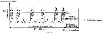
На фиг. 9 показан случай, когда при передаче преамбулы не используется концепция обратной связи. На фиг.10 и 11 показаны случаи, когда концепция обратной связи используется при передаче преамбулы на фиксированном интервале преамбулы и переменном интервале преамбулы соответственно. Здесь соответствующие мобильные станции передают преамбулы на базовую станцию на своих собственных выделенных интервалах передачи преамбулы. Это позволяет уменьшить помехи обратных каналов связи, которые могли бы в противном случае возникнуть под воздействием разных мобильных станций при одновременном запросе с их стороны на соединение с данной базовой станцией. In FIG. 9 shows a case where the feedback concept is not used in the transmission of the preamble. 10 and 11 show cases where the feedback concept is used when transmitting a preamble at a fixed preamble interval and a variable preamble interval, respectively. Here, the respective mobile stations transmit the preambles to the base station at their own dedicated preamble transmission intervals. This allows you to reduce the interference of the reverse communication channels, which could otherwise occur under the influence of different mobile stations while simultaneously requesting from them to connect to this base station.
Обратимся к фиг. 9, в интервале преамбулы интервалы передачи преамбулы Р1, Р3, Р7, Р10, Р14 и Р16 выделены для мобильной станции А. Мобильная станция А передает преамбулы на интервалах Р1, Р3, Р7, Р10, Р14 и Р16. Мобильная станция В передает преамбулы на интервалах Р2, Р5, Р7, Р9, Р12 и Р15. На интервале Р7 помехи могут возрасти из-за передачи преамбулы двумя мобильными станциями, но помехи на других каналах на других интервалах уменьшаются. То есть может быть уменьшено отношение пиковой мощности передачи преамбулы к средней мощности передачи преамбулы. Turning to FIG. 9, in the preamble interval, transmission intervals of the preamble P1, P3, P7, P10, P14 and P16 are allocated to mobile station A. Mobile station A transmits preambles at intervals P1, P3, P7, P10, P14 and P16. Mobile station B transmits preambles at intervals P2, P5, P7, P9, P12 and P15. On P7, interference may increase due to the transmission of the preamble by two mobile stations, but interference on other channels at other intervals is reduced. That is, the ratio of the peak transmit power of the preamble to the average transmit power of the preamble can be reduced.
Обратимся к фиг.10, где мобильная станция А передает сигнал преамбулы на выделенных для нее интервалах передачи Р1, Р3, Р7, Р10, Р14 и Р16 и проверяет, получена ли от базовой станции информация о вхождении в синхронизм. Как показано на этой фигуре, мобильная станция А передает сигнал преамбулы на интервале Р1 и проверяет на интервале Р2, получена ли от базовой станции информация о вхождении в синхронизм. Не получив информацию о вхождении в синхронизм, мобильная станция А передает на интервале Р3 сигнал преамбулы и проверяет на последующих интервалах Р4, Р5 и Р6, где преамбула не передается, получена ли от базовой станции информация о вхождении в синхронизм. Получив информацию о вхождении в синхронизм, мобильная станция А больше не передает преамбулу и посылает сообщение канала доступа в конце интервала передачи преамбулы. Referring to FIG. 10, where the mobile station A transmits the preamble signal at the transmission intervals P1, P3, P7, P10, P14 and P16 allocated to it and checks whether synchronization information is received from the base station. As shown in this figure, the mobile station A transmits a preamble signal in the interval P1 and checks in the interval P2 whether information about synchronization has been received from the base station. Having not received information on entering synchronism, mobile station A transmits a preamble signal at interval P3 and checks at subsequent intervals P4, P5 and P6, where the preamble is not transmitted if information about synchronization has been received from the base station. Upon receiving the synchronization information, the mobile station A no longer transmits the preamble and sends an access channel message at the end of the preamble transmission interval.
С другой стороны, как представлено на фиг.11, мобильная станция передает сигналы преамбулы на выделенных интервалах передачи преамбулы тем же способом, который описан в связи с фиг.10. Однако, получив информацию о вхождении в синхронизм, мобильная станция прерывает передачу преамбулы и одновременно посылает сообщение канала доступа на базовую станцию в следующем интервале передачи преамбулы. Здесь мощность передачи преамбулы возрастает на ΔХ каждый раз, когда мобильная станция передает сигнал преамбулы. Это делается с целью облегчения вхождения в синхронизм на базовой станции. Приращение мощности передачи ΔХ задается в виде системного параметра. В качестве альтернативы для достижения того же эффекта, что показан на фиг.11, преамбулы передаются на отдельном интервале передачи преамбулы, зафиксированном внутри интервала преамбулы, с начала изменяемых интервалов преамбулы. On the other hand, as shown in FIG. 11, the mobile station transmits the preamble signals at the allocated preamble transmission intervals in the same manner as described in connection with FIG. 10. However, having received the synchronization information, the mobile station interrupts the transmission of the preamble and simultaneously sends the message of the access channel to the base station in the next transmission interval of the preamble. Here, the transmission power of the preamble increases by ΔX each time the mobile station transmits the preamble signal. This is to facilitate entry into synchronism at the base station. The increment of the transmit power ΔX is set in the form of a system parameter. Alternatively, in order to achieve the same effect as shown in FIG. 11, the preambles are transmitted on a separate preamble transmission interval fixed within the preamble interval from the beginning of the variable preamble intervals.
Как было описано выше, настоящее изобретение имеет следующие преимущества по сравнению с известным способом передачи преамбулы. Во-первых, во время передачи по каналу доступа на базовую станцию мобильная станция передает преамбулу с перерывами, предотвращая использование мобильной станцией избыточной мощности передачи для обнаружения преамбулы и вхождения в синхронизм. Это уменьшает ненужное энергопотребление на мобильной станции, когда время ожидания увеличено, и предотвращает ухудшение качества обратных каналов связи. Во-вторых, в системе с фиксированным интервалом преамбулы базовая станция посылает на мобильную станцию информацию об обнаружении преамбулы и вхождении в синхронизм, так что мобильная станция приостанавливает передачу преамбулы на базовую станцию. Это уменьшает помехи в обратных каналах связи и мощность передачи на мобильной станции, увеличивая тем самым время ожидания мобильной станции. В-третьих, в системе с переменным интервалом преамбулы базовая станция посылает на мобильную станцию информацию об обнаружении преамбулы и вхождении в синхронизм для варьируемого укорачивания интервала преамбулы и обеспечивает более раннюю передачу сообщений. Это позволяет мобильной станции прерывать передачу преамбулы и уменьшать помехи в обратных каналах связи и мощность передачи. В результате время ожидания мобильной станции может быть продлено. As described above, the present invention has the following advantages over the known method for transmitting a preamble. First, during transmission over the access channel to the base station, the mobile station transmits the preamble intermittently, preventing the mobile station from using excessive transmission power to detect the preamble and enter synchronism. This reduces unnecessary power consumption at the mobile station when the latency is increased, and prevents degradation of the quality of the reverse communication channels. Secondly, in a system with a fixed preamble interval, the base station sends information about preamble detection and synchronization to the mobile station so that the mobile station stops transmitting the preamble to the base station. This reduces interference in the reverse channels and the transmit power of the mobile station, thereby increasing the latency of the mobile station. Thirdly, in a system with a variable preamble interval, the base station sends information to the mobile station about the detection of the preamble and entry into synchronism for a variable shortening of the preamble interval and provides earlier transmission of messages. This allows the mobile station to interrupt the transmission of the preamble and reduce interference in the reverse channels of communication and transmit power. As a result, the latency of the mobile station can be extended.
Хотя настоящее изобретение раскрыто на примере конкретных предпочтительных вариантов его осуществления для специалистов в данной области техники, очевидным является то, что в него могут быть внесены различные изменения по форме и в деталях, не выходящие за рамки сущности и объема изобретения, как они охарактеризованы в нижеследующей формуле изобретения. Although the present invention has been disclosed by way of specific preferred embodiments for those skilled in the art, it is obvious that various changes in form and detail may be made therein without departing from the spirit and scope of the invention as described in the following. the claims.
Claims (31)
Applications Claiming Priority (2)
| Application Number | Priority Date | Filing Date | Title |
|---|---|---|---|
| KR1019980033862A KR20000014424A (en) | 1998-08-17 | 1998-08-17 | Apparatus and method for transmitting preamble of access channel |
| KR1998/33862 | 1998-08-17 |
Publications (2)
| Publication Number | Publication Date |
|---|---|
| RU2000109575A RU2000109575A (en) | 2002-04-10 |
| RU2191479C2 true RU2191479C2 (en) | 2002-10-20 |
Family
ID=36462702
Family Applications (1)
| Application Number | Title | Priority Date | Filing Date |
|---|---|---|---|
| RU2000109575A RU2191479C2 (en) | 1998-08-17 | 1999-08-17 | Method and device for transmitting access channel preamble in mobile communication system |
Country Status (20)
| Country | Link |
|---|---|
| US (1) | US7054298B1 (en) |
| EP (2) | EP1392003B1 (en) |
| JP (1) | JP3542558B2 (en) |
| KR (1) | KR20000014424A (en) |
| CN (1) | CN1139214C (en) |
| AR (1) | AR022365A1 (en) |
| AT (2) | ATE261631T1 (en) |
| AU (1) | AU744158B2 (en) |
| BR (1) | BRPI9906732B1 (en) |
| CA (1) | CA2305889C (en) |
| DE (3) | DE69915450T2 (en) |
| DK (1) | DK1046222T3 (en) |
| ES (1) | ES2219044T3 (en) |
| ID (1) | ID25907A (en) |
| IL (1) | IL135627A0 (en) |
| PL (1) | PL200810B1 (en) |
| PT (1) | PT1046222E (en) |
| RU (1) | RU2191479C2 (en) |
| WO (1) | WO2000008908A2 (en) |
| ZA (1) | ZA200002174B (en) |
Cited By (26)
| Publication number | Priority date | Publication date | Assignee | Title |
|---|---|---|---|---|
| US7567639B2 (en) | 2004-04-28 | 2009-07-28 | Samsung Electronics Co., Ltd | Method and apparatus for generating preamble sequence for adaptive antenna system in orthogonal frequency division multiple access communication system |
| US7826855B2 (en) | 2006-01-05 | 2010-11-02 | Lg Electronics, Inc. | Data transmission method and data retransmission method |
| US7839829B2 (en) | 2006-02-07 | 2010-11-23 | Lg Electronics, Inc. | Method for transmitting response information in mobile communications system |
| US7881724B2 (en) | 2006-01-05 | 2011-02-01 | Lg Electronics Inc. | Allocating radio resources in mobile communications system |
| US8068473B2 (en) | 2006-02-07 | 2011-11-29 | Lg Electronics Inc. | Method for operating enhanced RLC entity and RNC entity for WCDMA and system thereof |
| US8072938B2 (en) | 2006-01-05 | 2011-12-06 | Lg Electronics, Inc. | Method for handover in mobile communication system |
| EA016075B1 (en) * | 2007-06-12 | 2012-01-30 | Шарп Кабусики Кайся | Mobile communication system, base station device, and processing method of the same |
| US8112091B2 (en) | 2006-01-05 | 2012-02-07 | Lg Electronics Inc. | Allocating radio resources in mobile communications system |
| US8135420B2 (en) | 2006-01-05 | 2012-03-13 | Lg Electronics Inc. | Method of transmitting/receiving a paging message in a wireless communication system |
| EA016371B1 (en) * | 2007-08-08 | 2012-04-30 | Шарп Кабусики Кайся | Radio communication system and mobile station device |
| US8189537B2 (en) | 2006-06-21 | 2012-05-29 | Lg Electronics Inc. | Method for reconfiguring radio link in wireless communication system |
| US8234534B2 (en) | 2006-06-21 | 2012-07-31 | Lg Electronics Inc. | Method of supporting data retransmission in a mobile communication system |
| US8243665B2 (en) | 2006-02-07 | 2012-08-14 | Lg Electronics Inc. | Method for selection and signaling of downlink and uplink bandwidth in wireless networks |
| US8248924B2 (en) | 2006-06-21 | 2012-08-21 | Lg Electronics Inc. | Uplink access method of mobile communication system |
| RU2464717C2 (en) * | 2008-03-28 | 2012-10-20 | Квэлкомм Инкорпорейтед | Preamble with low revolving use for wireless communication network |
| US8340026B2 (en) | 2006-01-05 | 2012-12-25 | Lg Electronics Inc. | Transmitting data in a mobile communication system |
| US8396020B2 (en) | 2006-01-05 | 2013-03-12 | Lg Electronics Inc. | Point-to-multipoint service communication |
| RU2479150C2 (en) * | 2006-10-03 | 2013-04-10 | Квэлкомм Инкорпорейтед | Transfer of alarm of random access for access to system in wireless communication |
| US8428086B2 (en) | 2006-01-05 | 2013-04-23 | Lg Electronics Inc. | Transmitting data in a mobile communication system |
| US8493854B2 (en) | 2006-02-07 | 2013-07-23 | Lg Electronics Inc. | Method for avoiding collision using identifier in mobile network |
| US8570956B2 (en) | 2006-06-21 | 2013-10-29 | Lg Electronics Inc. | Method of communicating data in a wireless mobile communications system using message separation and mobile terminal for use with the same |
| US8638707B2 (en) | 2006-06-21 | 2014-01-28 | Lg Electronics Inc. | Method for supporting quality of multimedia broadcast multicast service (MBMS) in mobile communications system and terminal thereof |
| US8644250B2 (en) | 2006-01-05 | 2014-02-04 | Lg Electronics Inc. | Maintaining communication between mobile terminal and network in mobile communication system |
| US8750217B2 (en) | 2006-01-05 | 2014-06-10 | Lg Electronics Inc. | Method for scheduling radio resources in mobile communication system |
| US8971288B2 (en) | 2006-03-22 | 2015-03-03 | Lg Electronics Inc. | Method of supporting handover in a wireless communication system |
| US9456455B2 (en) | 2006-01-05 | 2016-09-27 | Lg Electronics Inc. | Method of transmitting feedback information in a wireless communication system |
Families Citing this family (29)
| Publication number | Priority date | Publication date | Assignee | Title |
|---|---|---|---|---|
| US6606341B1 (en) | 1999-03-22 | 2003-08-12 | Golden Bridge Technology, Inc. | Common packet channel with firm handoff |
| US6549564B1 (en) * | 1999-04-08 | 2003-04-15 | Telefonaktiebolaget Lm Ericsson (Publ) | Random access in a mobile telecommunications system |
| US6643318B1 (en) | 1999-10-26 | 2003-11-04 | Golden Bridge Technology Incorporated | Hybrid DSMA/CDMA (digital sense multiple access/code division multiple access) method with collision resolution for packet communications |
| US6757319B1 (en) | 1999-11-29 | 2004-06-29 | Golden Bridge Technology Inc. | Closed loop power control for common downlink transport channels |
| US6480525B1 (en) | 1999-11-29 | 2002-11-12 | Golden Bridge Technology Inc. | Second level collision resolution for packet data communications |
| CN1146147C (en) * | 1999-12-13 | 2004-04-14 | 华为技术有限公司 | Method for base station to guide mobile station to reduce prefix emitted power |
| US6904079B2 (en) * | 2000-02-08 | 2005-06-07 | Ipr Licensing, Inc. | Access channel structure for wireless communication system |
| WO2001059968A1 (en) | 2000-02-09 | 2001-08-16 | Golden Bridge Technology, Inc. | Collision avoidance |
| KR20020030367A (en) | 2000-10-17 | 2002-04-25 | 오길록 | Random Access Transmission and Procedure for Mobile Satellite Communication Systems |
| KR100357706B1 (en) * | 2000-11-02 | 2002-10-25 | 주식회사 하이닉스반도체 | Apparatus for searching preamble a mobile communication base station transciever subsystem |
| KR100369651B1 (en) * | 2001-04-04 | 2003-02-05 | 삼성전자 주식회사 | Method for selecting rach in cdma mobile communication system |
| GB2382746B (en) | 2001-11-20 | 2005-12-14 | Ericsson Telefon Ab L M | Establishing radio communication channels |
| KR100766018B1 (en) * | 2001-12-29 | 2007-10-11 | 엘지전자 주식회사 | Transmission signal decision method for mobile communication system |
| KR20030085426A (en) * | 2002-04-30 | 2003-11-05 | 삼성전자주식회사 | Apparatus and method for transmitting packet data in a high packet data transmitting mobile communication system |
| US8099095B2 (en) * | 2003-02-25 | 2012-01-17 | Qualcomm Incorporated | Method and apparatus for controlling operation of an access terminal in a communication system |
| KR101022097B1 (en) * | 2003-07-08 | 2011-03-17 | 엘지전자 주식회사 | Synchronous acquisition method in mobile communication system |
| KR20050066562A (en) * | 2003-12-26 | 2005-06-30 | 삼성전자주식회사 | Method for embodying frame preamble in wireless communication based on ofdm, and method for acquiring frame synchronization and searching cells using the preamble |
| JP4212548B2 (en) * | 2003-12-26 | 2009-01-21 | 株式会社東芝 | Wireless transmission device, wireless reception device, wireless transmission method, and wireless reception method |
| US20050286547A1 (en) * | 2004-06-24 | 2005-12-29 | Baum Kevin L | Method and apparatus for accessing a wireless multi-carrier communication system |
| JP2006197173A (en) * | 2005-01-13 | 2006-07-27 | Oki Electric Ind Co Ltd | Radio communication apparatus, radio communication system and radio communication method |
| US8115604B2 (en) * | 2005-04-25 | 2012-02-14 | Lg Electronics Inc. | Reader control system |
| WO2008051037A1 (en) | 2006-10-25 | 2008-05-02 | Samsung Electronics Co., Ltd. | Method and apparatus for allocating radio resource using random access procedure in a mobile communication system |
| CN101246538A (en) * | 2007-02-14 | 2008-08-20 | 日电(中国)有限公司 | Radio frequency recognition system and method |
| US8369269B2 (en) * | 2007-09-18 | 2013-02-05 | Sharp Kabushiki Kaisha | Radio communication system, base station device, mobile station device, and random access method |
| WO2009072167A1 (en) * | 2007-12-06 | 2009-06-11 | Fujitsu Limited | Radio transmitting apparatus and radio transmitting method |
| CN101471727B (en) * | 2007-12-29 | 2013-04-10 | 京信通信系统(中国)有限公司 | Digitalization automatic frequency detection method based on true signal |
| US8804483B2 (en) * | 2009-07-31 | 2014-08-12 | Qualcomm Incorporated | System and method for transmission and detection of frame including bursts of pulses |
| WO2012144558A1 (en) * | 2011-04-22 | 2012-10-26 | Necカシオモバイルコミュニケーションズ株式会社 | Transmitter circuit, interface circuit, information terminal, interface method and recording medium |
| CN103458527B (en) * | 2012-06-01 | 2017-02-08 | 中兴通讯股份有限公司 | Preamble detection task processing and dispatching method and device |
Family Cites Families (13)
| Publication number | Priority date | Publication date | Assignee | Title |
|---|---|---|---|---|
| US4817146A (en) * | 1984-10-17 | 1989-03-28 | General Electric Company | Cryptographic digital signal transceiver method and apparatus |
| US4730307A (en) * | 1986-11-24 | 1988-03-08 | General Electric Company | Method and apparatus for local area networks |
| JP2810569B2 (en) * | 1991-09-30 | 1998-10-15 | 富士通株式会社 | Paging method |
| US5768305A (en) | 1994-11-29 | 1998-06-16 | Canon Kabushiki Kaisha | Identification of start and end points of transmitted data in spread spectrum communication systems |
| US5568509A (en) | 1995-03-20 | 1996-10-22 | General Electric Company | Dynamic code division multiple access communication system |
| US5745484A (en) * | 1995-06-05 | 1998-04-28 | Omnipoint Corporation | Efficient communication system using time division multiplexing and timing adjustment control |
| FI103082B (en) * | 1996-05-27 | 1999-04-15 | Nokia Telecommunications Oy | Connection set up procedure and radio system |
| JP3361694B2 (en) * | 1996-06-07 | 2003-01-07 | 株式会社エヌ・ティ・ティ・ドコモ | Pilot channel transmission and cell selection method in CDMA mobile communication system, mobile station |
| US6259724B1 (en) | 1996-10-18 | 2001-07-10 | Telefonaktiebolaget L M Ericsson (Publ) | Random access in a mobile telecommunications system |
| US5872775A (en) | 1996-10-30 | 1999-02-16 | Qualcomm Incorporated | Method and apparatus for performing rate determination |
| GB2330279B (en) * | 1997-10-07 | 1999-09-22 | Ramar Technology Ltd | Low power density radio systems |
| WO1999059268A1 (en) | 1998-05-13 | 1999-11-18 | Ntt Mobile Communications Network Inc. | Communication method and communication device |
| DK1101294T3 (en) | 1998-07-28 | 2011-03-28 | Samsung Electronics Co Ltd | Locked transmission in control-hold mode in CDMA communication system |
-
1998
- 1998-08-17 KR KR1019980033862A patent/KR20000014424A/en active Search and Examination
-
1999
- 1999-08-17 PT PT99938636T patent/PT1046222E/en unknown
- 1999-08-17 AR ARP990104108 patent/AR022365A1/en active IP Right Grant
- 1999-08-17 RU RU2000109575A patent/RU2191479C2/en active
- 1999-08-17 EP EP20030024529 patent/EP1392003B1/en not_active Expired - Lifetime
- 1999-08-17 CN CNB998013781A patent/CN1139214C/en not_active Expired - Lifetime
- 1999-08-17 US US09/376,743 patent/US7054298B1/en not_active Expired - Lifetime
- 1999-08-17 PL PL340919A patent/PL200810B1/en unknown
- 1999-08-17 CA CA002305889A patent/CA2305889C/en not_active Expired - Lifetime
- 1999-08-17 IL IL13562799A patent/IL135627A0/en not_active IP Right Cessation
- 1999-08-17 JP JP2000564424A patent/JP3542558B2/en not_active Expired - Lifetime
- 1999-08-17 AT AT99938636T patent/ATE261631T1/en active
- 1999-08-17 DE DE69915450T patent/DE69915450T2/en not_active Expired - Lifetime
- 1999-08-17 AT AT03024529T patent/ATE425593T1/en not_active IP Right Cessation
- 1999-08-17 EP EP99938636A patent/EP1046222B1/en not_active Expired - Lifetime
- 1999-08-17 ES ES99938636T patent/ES2219044T3/en not_active Expired - Lifetime
- 1999-08-17 DE DE29924418U patent/DE29924418U1/en not_active Expired - Lifetime
- 1999-08-17 ID ID20000677D patent/ID25907A/en unknown
- 1999-08-17 AU AU53076/99A patent/AU744158B2/en not_active Expired
- 1999-08-17 DK DK99938636T patent/DK1046222T3/en active
- 1999-08-17 DE DE69940568T patent/DE69940568D1/en not_active Expired - Lifetime
- 1999-08-17 WO PCT/KR1999/000457 patent/WO2000008908A2/en active IP Right Grant
- 1999-08-17 BR BRPI9906732A patent/BRPI9906732B1/en not_active IP Right Cessation
-
2000
- 2000-05-04 ZA ZA200002174A patent/ZA200002174B/en unknown
Cited By (60)
| Publication number | Priority date | Publication date | Assignee | Title |
|---|---|---|---|---|
| US7567639B2 (en) | 2004-04-28 | 2009-07-28 | Samsung Electronics Co., Ltd | Method and apparatus for generating preamble sequence for adaptive antenna system in orthogonal frequency division multiple access communication system |
| US8428086B2 (en) | 2006-01-05 | 2013-04-23 | Lg Electronics Inc. | Transmitting data in a mobile communication system |
| USRE43949E1 (en) | 2006-01-05 | 2013-01-29 | Lg Electronics Inc. | Allocating radio resources in mobile communications system |
| US8867449B2 (en) | 2006-01-05 | 2014-10-21 | Lg Electronics Inc. | Transmitting data in a mobile communication system |
| US9036596B2 (en) | 2006-01-05 | 2015-05-19 | Lg Electronics Inc. | Transmitting data in a mobile communication system |
| US7869396B2 (en) | 2006-01-05 | 2011-01-11 | Lg Electronics, Inc. | Data transmission method and data re-transmission method |
| US7881724B2 (en) | 2006-01-05 | 2011-02-01 | Lg Electronics Inc. | Allocating radio resources in mobile communications system |
| US7826855B2 (en) | 2006-01-05 | 2010-11-02 | Lg Electronics, Inc. | Data transmission method and data retransmission method |
| US9253801B2 (en) | 2006-01-05 | 2016-02-02 | Lg Electronics Inc. | Maintaining communication between mobile terminal and network in mobile communication system |
| US9397791B2 (en) | 2006-01-05 | 2016-07-19 | Lg Electronics Inc. | Transmitting data in a mobile communication system |
| US8750217B2 (en) | 2006-01-05 | 2014-06-10 | Lg Electronics Inc. | Method for scheduling radio resources in mobile communication system |
| US8072938B2 (en) | 2006-01-05 | 2011-12-06 | Lg Electronics, Inc. | Method for handover in mobile communication system |
| US8112091B2 (en) | 2006-01-05 | 2012-02-07 | Lg Electronics Inc. | Allocating radio resources in mobile communications system |
| US8135420B2 (en) | 2006-01-05 | 2012-03-13 | Lg Electronics Inc. | Method of transmitting/receiving a paging message in a wireless communication system |
| US8165596B2 (en) | 2006-01-05 | 2012-04-24 | Lg Electronics Inc. | Data transmission method and data re-transmission method |
| US9955507B2 (en) | 2006-01-05 | 2018-04-24 | Lg Electronics Inc. | Maintaining communication between mobile terminal and network in mobile communication system |
| US8396020B2 (en) | 2006-01-05 | 2013-03-12 | Lg Electronics Inc. | Point-to-multipoint service communication |
| US8369865B2 (en) | 2006-01-05 | 2013-02-05 | Lg Electronics Inc. | Data transmission method and data re-transmission method |
| US9456455B2 (en) | 2006-01-05 | 2016-09-27 | Lg Electronics Inc. | Method of transmitting feedback information in a wireless communication system |
| US8340026B2 (en) | 2006-01-05 | 2012-12-25 | Lg Electronics Inc. | Transmitting data in a mobile communication system |
| US8644250B2 (en) | 2006-01-05 | 2014-02-04 | Lg Electronics Inc. | Maintaining communication between mobile terminal and network in mobile communication system |
| US8081660B2 (en) | 2006-02-07 | 2011-12-20 | Lg Electronics, Inc. | Method for requesting radio resource in mobile communications system |
| US8085738B2 (en) | 2006-02-07 | 2011-12-27 | Lg Electronics Inc. | Preamble retransmission method in mobile communications system |
| US8238371B2 (en) | 2006-02-07 | 2012-08-07 | Lg Electronics Inc. | Method for operating enhanced RLC entity and RNC entity for WCDMA and system thereof |
| US9462576B2 (en) | 2006-02-07 | 2016-10-04 | Lg Electronics Inc. | Method for transmitting response information in mobile communications system |
| US8223713B2 (en) | 2006-02-07 | 2012-07-17 | Lg Electronics Inc. | Method for transmitting response information in mobile communications system |
| US9706580B2 (en) | 2006-02-07 | 2017-07-11 | Lg Electronics Inc. | Method for transmitting response information in mobile communications system |
| US8175052B2 (en) | 2006-02-07 | 2012-05-08 | Lg Electronics Inc. | Method for transmitting response information in mobile communications system |
| US8406190B2 (en) | 2006-02-07 | 2013-03-26 | Lg Electronics Inc. | Method for transmitting response information in mobile communications system |
| US10045381B2 (en) | 2006-02-07 | 2018-08-07 | Lg Electronics Inc. | Method for transmitting response information in mobile communications system |
| US8243665B2 (en) | 2006-02-07 | 2012-08-14 | Lg Electronics Inc. | Method for selection and signaling of downlink and uplink bandwidth in wireless networks |
| US8068473B2 (en) | 2006-02-07 | 2011-11-29 | Lg Electronics Inc. | Method for operating enhanced RLC entity and RNC entity for WCDMA and system thereof |
| US8437335B2 (en) | 2006-02-07 | 2013-05-07 | Lg Electronics Inc. | Method for transmitting response information in mobile communications system |
| US8451821B2 (en) | 2006-02-07 | 2013-05-28 | Lg Electronics Inc. | Method for transmitting response information in mobile communications system |
| US7848308B2 (en) | 2006-02-07 | 2010-12-07 | Lg Electronics, Inc. | Method for transmitting response information in mobile communications system |
| US8493854B2 (en) | 2006-02-07 | 2013-07-23 | Lg Electronics Inc. | Method for avoiding collision using identifier in mobile network |
| US7839829B2 (en) | 2006-02-07 | 2010-11-23 | Lg Electronics, Inc. | Method for transmitting response information in mobile communications system |
| US7843877B2 (en) | 2006-02-07 | 2010-11-30 | Lg Electronics, Inc. | Method for transmitting response information in mobile communications system |
| US8971288B2 (en) | 2006-03-22 | 2015-03-03 | Lg Electronics Inc. | Method of supporting handover in a wireless communication system |
| US8429478B2 (en) | 2006-06-21 | 2013-04-23 | Lg Electronics Inc. | Method of supporting data retransmission in a mobile communication system |
| US8638707B2 (en) | 2006-06-21 | 2014-01-28 | Lg Electronics Inc. | Method for supporting quality of multimedia broadcast multicast service (MBMS) in mobile communications system and terminal thereof |
| US8570956B2 (en) | 2006-06-21 | 2013-10-29 | Lg Electronics Inc. | Method of communicating data in a wireless mobile communications system using message separation and mobile terminal for use with the same |
| US8189537B2 (en) | 2006-06-21 | 2012-05-29 | Lg Electronics Inc. | Method for reconfiguring radio link in wireless communication system |
| US8234534B2 (en) | 2006-06-21 | 2012-07-31 | Lg Electronics Inc. | Method of supporting data retransmission in a mobile communication system |
| US8248924B2 (en) | 2006-06-21 | 2012-08-21 | Lg Electronics Inc. | Uplink access method of mobile communication system |
| US9220093B2 (en) | 2006-06-21 | 2015-12-22 | Lg Electronics Inc. | Method of supporting data retransmission in a mobile communication system |
| RU2479150C2 (en) * | 2006-10-03 | 2013-04-10 | Квэлкомм Инкорпорейтед | Transfer of alarm of random access for access to system in wireless communication |
| US8599706B2 (en) | 2006-10-03 | 2013-12-03 | Qualcomm Incorporated | Random access signaling transmission for system access in wireless communication |
| US8462712B2 (en) | 2007-06-12 | 2013-06-11 | Sharp Kabushiki Kaisha | Base station device, mobile station device, program, uplink synchronization requesting method, and synchronization-shift measurement signal transmitting method |
| US11930510B2 (en) | 2007-06-12 | 2024-03-12 | MiiCs & Partners Japan Co., Ltd. | Base station device, mobile station device, program, uplink synchronization requesting method, and synchronization-shift measurement signal transmitting method |
| US9094168B2 (en) | 2007-06-12 | 2015-07-28 | Sharp Kabushiki Kaisha | Base station device, mobile station device, program, uplink synchronization requesting method, and synchronization-shift measurement signal transmitting method |
| US8681716B2 (en) | 2007-06-12 | 2014-03-25 | Sharp Kabushiki Kaisha | Base station device, mobile station device, program, uplink synchronization requesting method, and synchronization-shift measurement signal transmitting method |
| US9516631B2 (en) | 2007-06-12 | 2016-12-06 | Sharp Kabushiki Kaisha | Base station device, mobile station device, program, uplink synchronization requesting method, and synchronization-shift measurement signal transmitting method |
| EA016075B1 (en) * | 2007-06-12 | 2012-01-30 | Шарп Кабусики Кайся | Mobile communication system, base station device, and processing method of the same |
| US11012987B2 (en) | 2007-06-12 | 2021-05-18 | Sharp Kabushiki Kaisha | Base station device, mobile station device, program, uplink synchronization requesting method, and synchronization-shift measurement signal transmitting method |
| US10085250B2 (en) | 2007-06-12 | 2018-09-25 | Sharp Kabushiki Kaisha | Base station device, mobile station device, program, uplink synchronization requesting method, and synchronization-shift measurement signal transmitting method |
| US9094909B2 (en) | 2007-08-08 | 2015-07-28 | Huawei Technologies Co., Ltd. | Conditional uplink timing alignment in a mobile station device of a radio communication system |
| EA016371B1 (en) * | 2007-08-08 | 2012-04-30 | Шарп Кабусики Кайся | Radio communication system and mobile station device |
| US9913256B2 (en) | 2007-08-08 | 2018-03-06 | Huawei Technologies Co., Ltd. | Conditional uplink timing alignment in a mobile station device of a radio communication system |
| RU2464717C2 (en) * | 2008-03-28 | 2012-10-20 | Квэлкомм Инкорпорейтед | Preamble with low revolving use for wireless communication network |
Also Published As
| Publication number | Publication date |
|---|---|
| CN1139214C (en) | 2004-02-18 |
| US7054298B1 (en) | 2006-05-30 |
| ES2219044T3 (en) | 2004-11-16 |
| CA2305889C (en) | 2003-12-30 |
| DE69940568D1 (en) | 2009-04-23 |
| WO2000008908A2 (en) | 2000-02-24 |
| BR9906732A (en) | 2000-12-05 |
| PT1046222E (en) | 2004-08-31 |
| EP1392003A2 (en) | 2004-02-25 |
| DE69915450T2 (en) | 2004-08-05 |
| BRPI9906732B1 (en) | 2016-03-01 |
| DE69915450D1 (en) | 2004-04-15 |
| ATE261631T1 (en) | 2004-03-15 |
| JP2002522994A (en) | 2002-07-23 |
| KR20000014424A (en) | 2000-03-15 |
| IL135627A0 (en) | 2001-05-20 |
| DE29924418U1 (en) | 2003-03-27 |
| EP1392003B1 (en) | 2009-03-11 |
| AR022365A1 (en) | 2002-09-04 |
| EP1392003A3 (en) | 2004-04-28 |
| CN1286847A (en) | 2001-03-07 |
| PL340919A1 (en) | 2001-03-12 |
| AU744158B2 (en) | 2002-02-14 |
| CA2305889A1 (en) | 2000-02-24 |
| JP3542558B2 (en) | 2004-07-14 |
| PL200810B1 (en) | 2009-02-27 |
| ATE425593T1 (en) | 2009-03-15 |
| DK1046222T3 (en) | 2004-04-19 |
| ZA200002174B (en) | 2001-10-02 |
| WO2000008908A3 (en) | 2000-07-13 |
| ID25907A (en) | 2000-11-09 |
| EP1046222A1 (en) | 2000-10-25 |
| AU5307699A (en) | 2000-03-06 |
| EP1046222B1 (en) | 2004-03-10 |
Similar Documents
| Publication | Publication Date | Title |
|---|---|---|
| RU2191479C2 (en) | Method and device for transmitting access channel preamble in mobile communication system | |
| RU2204220C2 (en) | Random access in mobile communication system | |
| EP0639899B2 (en) | Random access communication method by use of cdma, and system for mobile stations which use the method | |
| JP3880956B2 (en) | Remote station for common packet channel | |
| US6345066B1 (en) | Reduction of access time delay in frequency-hopping radio systems using a direct sequence mode | |
| JP4200180B2 (en) | System for controlling transmission power rise by using short codes in wireless CDMA system | |
| US6549545B1 (en) | Pilot signal detection method and receiver | |
| US5699380A (en) | Spread spectrum communication terminal apparatus in CDMA cellular telephone system | |
| EP0991189B1 (en) | Method of performing automatic frequency control in a mobile station during communication mode | |
| JP2857028B2 (en) | Road-to-vehicle communication method | |
| US5668829A (en) | Spread spectrum communication apparatus | |
| US6385182B1 (en) | Mobile-station transmitter/receiver | |
| KR100360004B1 (en) | Pilot signal reception method and receiver | |
| JP2002519887A (en) | Method and apparatus for storing and accessing different chip sequences | |
| JPH08162999A (en) | Diffuse spectrum communication system | |
| JPH1198109A (en) | Mobile radio receiver | |
| JPH11313027A (en) | Mobile communication system |