RU2187373C1 - Multilevel plant for recovery of valuable minerals - Google Patents
Multilevel plant for recovery of valuable minerals Download PDFInfo
- Publication number
- RU2187373C1 RU2187373C1 RU2001102769/03A RU2001102769A RU2187373C1 RU 2187373 C1 RU2187373 C1 RU 2187373C1 RU 2001102769/03 A RU2001102769/03 A RU 2001102769/03A RU 2001102769 A RU2001102769 A RU 2001102769A RU 2187373 C1 RU2187373 C1 RU 2187373C1
- Authority
- RU
- Russia
- Prior art keywords
- density fraction
- plant
- decks
- installation
- valuable minerals
- Prior art date
Links
- 229910052500 inorganic mineral Inorganic materials 0.000 title claims abstract description 14
- 239000011707 mineral Substances 0.000 title claims abstract description 14
- 238000011084 recovery Methods 0.000 title abstract 3
- XLYOFNOQVPJJNP-UHFFFAOYSA-N water Substances O XLYOFNOQVPJJNP-UHFFFAOYSA-N 0.000 claims abstract description 13
- 238000000605 extraction Methods 0.000 claims abstract description 8
- 238000006073 displacement reaction Methods 0.000 claims abstract 2
- 238000009434 installation Methods 0.000 claims description 22
- 238000011010 flushing procedure Methods 0.000 claims description 13
- 238000006386 neutralization reaction Methods 0.000 claims description 8
- 230000007246 mechanism Effects 0.000 claims description 5
- 238000000034 method Methods 0.000 abstract description 7
- 230000001988 toxicity Effects 0.000 abstract description 5
- 231100000419 toxicity Toxicity 0.000 abstract description 5
- 238000005516 engineering process Methods 0.000 abstract description 3
- 230000001360 synchronised effect Effects 0.000 abstract description 2
- 238000009877 rendering Methods 0.000 abstract 2
- 230000000694 effects Effects 0.000 abstract 1
- 239000000126 substance Substances 0.000 abstract 1
- 239000000203 mixture Substances 0.000 description 5
- 241000566515 Nedra Species 0.000 description 3
- 239000013067 intermediate product Substances 0.000 description 3
- 230000003472 neutralizing effect Effects 0.000 description 3
- 239000002245 particle Substances 0.000 description 3
- 150000003568 thioethers Chemical class 0.000 description 3
- 101150047356 dec-1 gene Proteins 0.000 description 2
- 238000005188 flotation Methods 0.000 description 2
- 238000009825 accumulation Methods 0.000 description 1
- 230000004913 activation Effects 0.000 description 1
- 238000004140 cleaning Methods 0.000 description 1
- 239000012141 concentrate Substances 0.000 description 1
- 239000012467 final product Substances 0.000 description 1
- 230000005484 gravity Effects 0.000 description 1
- 239000010410 layer Substances 0.000 description 1
- 230000010355 oscillation Effects 0.000 description 1
- 239000000047 product Substances 0.000 description 1
- 239000002356 single layer Substances 0.000 description 1
- 229910052569 sulfide mineral Inorganic materials 0.000 description 1
Images
Landscapes
- Paper (AREA)
Abstract
Description
Изобретение относится к области обогащения полезных ископаемых из руд и россыпей гравитационным способом динамического типа в тонкослойных потоках на аппаратах, сочетающих принципы обогащения на концентрационных столах обычного типа и вращающихся с активизацией процесса обезвреживания промпродукта. The invention relates to the field of beneficiation of minerals from ores and placers by the gravitational method of the dynamic type in thin-layer flows on apparatuses that combine the principles of enrichment on concentration tables of a conventional type and rotate with the activation of the process of neutralizing the intermediate product.
Известен стол Холман - Мичел для пленочной флотации сульфидов, содержащий деку, привод колебаний деки, систему воздушных трубок, покрывающих половину площади деки, систему подачи пульпы, систему для смыва концентрата (Берт Р.Д. Технология гравитационного обогащения. - М.: Недра, с. 311). The famous Holman-Michel table for film flotation of sulfides containing a deck, a deck oscillation drive, a system of air tubes covering half of the deck area, a pulp feeding system, a concentrate flushing system (Burt R.D. Gravity enrichment technology. - M .: Nedra, p. 311).
Установка позволяет решить вопрос снижения токсичности промпродукта путем пленочной флотации, но не обеспечивает достаточную эффективность извлечения ценных минералов. The installation allows you to solve the problem of reducing the toxicity of the intermediate by film flotation, but does not provide sufficient efficiency for the extraction of valuable minerals.
Известен круглый, выпуклый, конический стол двух типов. Первый - стол медленно вращается с частотой 2-5 мин-1, проходя под точками подачи пульпы, смывной воды и очистки. Второй - дека неподвижна, а питание, система промывки и очистители вращаются (Берт Р.Д. Технология гравитационного обогащения. - М.: Недра, с. 311).Known round, convex, conical table of two types. First, the table rotates slowly with a frequency of 2-5 min -1 , passing under the points of pulp supply, flushing water and cleaning. The second - the deck is stationary, and the power, flushing system and cleaners rotate (Bert R.D. Technology of gravitational enrichment. - M .: Nedra, p. 311).
Недостаток этих столов в том, что они могут быть применены только для монослоя частиц. The disadvantage of these tables is that they can only be used for a monolayer of particles.
Наиболее близкой по технической сущности и по результату, достигаемому при ее использовании, является многоуровневая установка для извлечения ценных минералов, включающая установленные на нескольких уровнях деки с рифлями, опорами и креновыми механизмами, привод, систему подачи пульпы и воды для смыва с распределителем. (см. Справочник по обогащению руд. Основные процессы. / Под. ред. О.С.Богданова. - М.: Недра, 1983, с. 90-97 - прототип). The closest in technical essence and in the result achieved when using it is a multi-level installation for the extraction of valuable minerals, including decks with flutes, supports and roll mechanisms installed at several levels, a drive, a pulp and water supply system for flushing with a distributor. (see. Guide to ore dressing. The main processes. / Under the editorship of O.S. Bogdanov. - M .: Nedra, 1983, pp. 90-97 - prototype).
Данная установка не извлекает ценные минералы мелких фракций (-0,2 мм) в широком диапазоне размерного ряда, например, до +0,06 мм и не обеспечивает снижение токсичности промежуточного и конечного продукта при переработке россыпей, содержащих сульфидные минералы. This installation does not extract valuable minerals of small fractions (-0.2 mm) in a wide range of size range, for example, up to +0.06 mm and does not reduce the toxicity of the intermediate and final product when processing placers containing sulfide minerals.
Цель изобретения - повышение эффективности извлечения ценных минералов со снижением токсичности промпродуктов процесса. The purpose of the invention is to increase the efficiency of the extraction of valuable minerals with a decrease in the toxicity of intermediate products of the process.
Поставленная цель достигается тем, что многоуровневая установка для извлечения ценных минералов, включающая установленные на нескольких уровнях деки с рифлями, опорами и креновыми механизмами, привод, систему подачи пульпы и воды для смыва с распределителем, согласно изобретению снабжена системой обезвреживания, при этом деки выполнены в виде секторов и установлены со смещением над желобами для фракции высокой плотности на каждом уровне, причем желоба для приема фракции высокой плотности установлены по внутреннему периметру установки на нескольких уровнях с наклонами днищ в сторону разгрузки фракции высокой плотности, а желоб для приема фракции низкой плотности установлен по наружному периметру установки с наклоном дна в сторону разгрузки фракции низкой плотности с установки, при этом привод выполнен с возможностью обеспечения синхронного вращения распределителя системы подачи пульпы и воды для смыва с деками вокруг общей оси. This goal is achieved by the fact that a multi-level installation for the extraction of valuable minerals, including decks with flutes, supports and roll mechanisms, a drive, a pulp and water supply system for flushing with a distributor, according to the invention, is equipped with a neutralization system, while the decks are made in sectors and are installed with an offset above the gutters for the high-density fraction at each level, and the gutters for receiving the high-density fraction are installed along the inner perimeter of the installation at several levels with tilts of the bottoms in the direction of discharge of the high density fraction, and a chute for receiving the fraction of low density is installed along the outer perimeter of the installation with a slope of the bottom in the direction of discharge of the fraction of low density from the installation, while the drive is designed to synchronously rotate the distributor of the pulp feed system and flushing water with decks around a common axis.
На чертежах представлена многоуровневая установка для извлечения ценных минералов. The drawings show a multi-level installation for the extraction of valuable minerals.
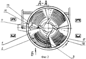
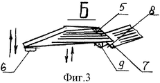
На фиг.1 - общий вид установки; на фиг.2 - разрез А-А на фиг.1; на фиг.3 - вид Б на фиг.2, расположение деки над желобом для фракции высокой плотности, сопряженного с предыдущей декой. Figure 1 - General view of the installation; figure 2 is a section aa in figure 1; figure 3 is a view of B in figure 2, the location of the deck above the chute for the high-density fraction associated with the previous deck.
Установка содержит деки 1 с рифлями 2. Деки 1 выполнены в виде секторов 3 на четверть круга и установлены по четыре деки 1 на каждом уровне 4. The installation contains decks 1 with
Каждая дека 1 имеет регулируемые опоры 5 и креновые механизмы 6 для настройки наклона дек 1 в сторону перемещения фракции высокой плотности и в сторону перемещения фракции низкой плотности поперек дек 1. На каждом уровне 4 любая последующая дека 1 устанавливается с зазором 7, со смещением 8 над желобом для фракции высокой плотности 9 предыдущей деки 1. Each deck 1 has
Привод 10 обеспечивает синхронное вращение вокруг общей оси 11 распределителя 12 подачи пульпы и воды для смыва с деками 1, установленными в нескольких уровнях 4. The drive 10 provides synchronous rotation around the common axis 11 of the distributor 12 for the supply of pulp and water for flushing with decks 1 installed in several levels 4.
Желоба для приема фракции высокой плотности 13 установлены по внутреннему периметру 14 установки в несколько уровней 4 с наклоном днищ 15 в сторону разгрузки фракции высокой плотности 16 с установки. Желоб для приема фракции низкой плотности 17 установлен по наружному периметру 18 установки с наклоном дна 19 в сторону разгрузки фракции низкой плотности 20 с установки. The gutters for receiving the
Система подачи пульпы и воды для смыва 21 и система обезвреживания 22 установлены на раме 23. The pulp and water supply system for flushing 21 and the neutralization system 22 are mounted on the frame 23.
Установка работает следующим образом. Installation works as follows.
С помощью креновых механизмов 6 и опор 5 производится регулировка положения секторов 3 дек 1 на каждом уровне 4 и их фиксация. Using the
Каждая последующая дека 1 устанавливается с зазором 7 со смещением 8 над желобом для фракции высокой плотности 9 предыдущей деки 1. Each subsequent deck 1 is installed with a gap of 7 with an offset of 8 above the chute for the
Включается привод 10. Деки 1, установленные в нескольких уровнях 4, начинают вращаться вокруг общей оси 11. Синхронно декам 1 с помощью привода 10 вращается распределитель 12 подачи пульпы и воды для смыва. Подается на деки 1 пульпа. The drive 10 is turned on. Decks 1, installed in several levels 4, begin to rotate around a common axis 11. Synchronously to the decks 1, the distributor 12 for feeding the pulp and water for flushing rotates with the help of the drive 10. Served on deck 1 pulp.
На поверхности дек 1 под действием гравитационных, гидродинамических, архимедовой и центробежных сил происходит разделение частиц различной плотности. On the surface of deck 1 under the influence of gravitational, hydrodynamic, archimedean and centrifugal forces, particles of different densities are separated.
Попадая в зону рифлей 2 на секторе 3 каждой из дек 1, частицы высокой плотности перемещаются к желобу для фракции высокой плотности 9, установленному по крайней кромке со стороны разгрузки деки 1. Getting into the zone of the
Фракция низкой плотности перемещается поперек дек 1 и попадает в желоб для приема фракции низкой плотности 17, установленный по наружному периметру 18 установки. The low density fraction moves across the deck 1 and enters the trough to receive the
Одновременно подается состав для обезвреживания сульфидов в желоб для приема фракции низкой плотности 17. At the same time, a composition for neutralizing sulfides is fed into the gutter to receive a
При достаточном накоплении фракции высокой плотности между рифлей 2 дек 1 подача пульпы прекращается и из системы подачи пульпы и воды для смыва 21 через распределитель 12 подачи пульпы и воды для смыва подается вода для смыва. With sufficient accumulation of high-density fractions between the flutes on Dec 2, the pulp supply is stopped, and flush water is supplied from the pulp and water supply system for flushing 21 through the distributor 12 for supplying pulp and water for flushing.
Вся накопленная фракция высокой плотности с дек 1 каждого уровня 4 по желобу для фракции высокой плотности 9 поступает в желоба для приема фракции высокой плотности 13, установленные по внутреннему периметру 14 установки на каждом из уровней 4. The entire accumulated high density fraction from Dec 1 of each level 4 through the gutter for the
Из системы обезвреживания 22, установленной на раме 23, в желоб для приема фракции высокой плотности 13 подается дозированный состав для обезвреживания сульфидов. From the neutralization system 22 installed on the frame 23, a metered composition for neutralizing sulfides is fed into the trough for receiving a
Наклон днищ 15 в сторону разгрузки фракции высокой плотности 16 позволяет составу обезвреживания, подаваемому с противоположной стороны, равномерно распределиться по поверхности выделенной фракции. После обезвреживания фракция высокой плотности выгружается. The inclination of the bottoms 15 in the direction of discharge of the high-density fraction 16 allows the neutralization composition supplied from the opposite side to be evenly distributed over the surface of the selected fraction. After neutralization, the high density fraction is discharged.
Обезвреживание фракции низкой плотности осуществляется циклически в процессе работы установки путем дозированной подачи состава обезвреживания со стороны, противоположной разгрузке фракции низкой плотности 20. Состав равномерно распределяется за счет наклона дна 19. The neutralization of the low density fraction is carried out cyclically during the operation of the installation by dosing the neutralization composition from the side opposite to the discharge of the low density fraction 20. The composition is evenly distributed due to the inclination of the bottom 19.
Установка обеспечивает эффективность извлечения ценных минералов и снижает токсичность продуктов обогащения. The installation provides the efficiency of extraction of valuable minerals and reduces the toxicity of enrichment products.
Claims (1)
Priority Applications (1)
| Application Number | Priority Date | Filing Date | Title |
|---|---|---|---|
| RU2001102769/03A RU2187373C1 (en) | 2001-01-30 | 2001-01-30 | Multilevel plant for recovery of valuable minerals |
Applications Claiming Priority (1)
| Application Number | Priority Date | Filing Date | Title |
|---|---|---|---|
| RU2001102769/03A RU2187373C1 (en) | 2001-01-30 | 2001-01-30 | Multilevel plant for recovery of valuable minerals |
Publications (1)
| Publication Number | Publication Date |
|---|---|
| RU2187373C1 true RU2187373C1 (en) | 2002-08-20 |
Family
ID=20245434
Family Applications (1)
| Application Number | Title | Priority Date | Filing Date |
|---|---|---|---|
| RU2001102769/03A RU2187373C1 (en) | 2001-01-30 | 2001-01-30 | Multilevel plant for recovery of valuable minerals |
Country Status (1)
| Country | Link |
|---|---|
| RU (1) | RU2187373C1 (en) |
Cited By (5)
| Publication number | Priority date | Publication date | Assignee | Title |
|---|---|---|---|---|
| RU2232055C1 (en) * | 2003-01-29 | 2004-07-10 | Институт горного дела Дальневосточного отделения РАН | Multilevel concentration complex with ultrasonic initiation |
| RU2292953C2 (en) * | 2004-02-13 | 2007-02-10 | Александр Григорьевич Павлушин | Gravitational apparatus to upgrade the finely crushed ores and slimes |
| RU2372994C1 (en) * | 2008-07-30 | 2009-11-20 | Государственное образовательное учреждение высшего профессионального образования "Санкт-Петербургский государственный горный институт имени Г.В. Плеханова (технический университет)" | Concentrate board |
| RU2380163C1 (en) * | 2008-09-26 | 2010-01-27 | Государственное образовательное учреждение высшего профессионального образования "Санкт-Петербургский государственный горный институт имени Г.В. Плеханова (технический университет)" | Gravitational electromagnetic separator |
| RU2438788C2 (en) * | 2009-12-21 | 2012-01-10 | Государственное образовательное учреждение высшего профессионального образования "Санкт-Петербургский государственный горный институт имени Г.В. Плеханова (технический университет)" | Disk concentration table |
Citations (6)
| Publication number | Priority date | Publication date | Assignee | Title |
|---|---|---|---|---|
| GB1009395A (en) * | 1962-05-22 | 1965-11-10 | Dei Con Eastern Corp | Concentrating table |
| US4521302A (en) * | 1984-04-05 | 1985-06-04 | Stone Spencer A | End elevation adjustment of material separating tables |
| WO1989010197A1 (en) * | 1988-04-26 | 1989-11-02 | Paul Allan Marriott | Separator |
| SU1745338A1 (en) * | 1988-06-21 | 1992-07-07 | Всесоюзный научно-исследовательский и проектный институт механической обработки полезных ископаемых "Механобр" | Concentrator for sludges |
| RU2004335C1 (en) * | 1991-11-26 | 1993-12-15 | Специальное конструкторское бюро горно-обогатительного оборудовани | Table for concentrate making |
| RU2149690C1 (en) * | 1998-06-24 | 2000-05-27 | Леонов Виктор Васильевич | Concentration table |
-
2001
- 2001-01-30 RU RU2001102769/03A patent/RU2187373C1/en not_active IP Right Cessation
Patent Citations (6)
| Publication number | Priority date | Publication date | Assignee | Title |
|---|---|---|---|---|
| GB1009395A (en) * | 1962-05-22 | 1965-11-10 | Dei Con Eastern Corp | Concentrating table |
| US4521302A (en) * | 1984-04-05 | 1985-06-04 | Stone Spencer A | End elevation adjustment of material separating tables |
| WO1989010197A1 (en) * | 1988-04-26 | 1989-11-02 | Paul Allan Marriott | Separator |
| SU1745338A1 (en) * | 1988-06-21 | 1992-07-07 | Всесоюзный научно-исследовательский и проектный институт механической обработки полезных ископаемых "Механобр" | Concentrator for sludges |
| RU2004335C1 (en) * | 1991-11-26 | 1993-12-15 | Специальное конструкторское бюро горно-обогатительного оборудовани | Table for concentrate making |
| RU2149690C1 (en) * | 1998-06-24 | 2000-05-27 | Леонов Виктор Васильевич | Concentration table |
Non-Patent Citations (1)
| Title |
|---|
| Справочник по обогащению руд. Основные процессы /Под. ред. БОГДАНОВА О.С. - М.: Недра, 1983, с. 90-97. * |
Cited By (5)
| Publication number | Priority date | Publication date | Assignee | Title |
|---|---|---|---|---|
| RU2232055C1 (en) * | 2003-01-29 | 2004-07-10 | Институт горного дела Дальневосточного отделения РАН | Multilevel concentration complex with ultrasonic initiation |
| RU2292953C2 (en) * | 2004-02-13 | 2007-02-10 | Александр Григорьевич Павлушин | Gravitational apparatus to upgrade the finely crushed ores and slimes |
| RU2372994C1 (en) * | 2008-07-30 | 2009-11-20 | Государственное образовательное учреждение высшего профессионального образования "Санкт-Петербургский государственный горный институт имени Г.В. Плеханова (технический университет)" | Concentrate board |
| RU2380163C1 (en) * | 2008-09-26 | 2010-01-27 | Государственное образовательное учреждение высшего профессионального образования "Санкт-Петербургский государственный горный институт имени Г.В. Плеханова (технический университет)" | Gravitational electromagnetic separator |
| RU2438788C2 (en) * | 2009-12-21 | 2012-01-10 | Государственное образовательное учреждение высшего профессионального образования "Санкт-Петербургский государственный горный институт имени Г.В. Плеханова (технический университет)" | Disk concentration table |
Similar Documents
| Publication | Publication Date | Title |
|---|---|---|
| US4128474A (en) | Process for cleaning and dewatering fine coal | |
| US2964181A (en) | Grading and separating device | |
| US4961843A (en) | Lewis econosizer for hydraulically classifying particles | |
| US4826017A (en) | Vibrating screen | |
| RU2187373C1 (en) | Multilevel plant for recovery of valuable minerals | |
| RU2187372C1 (en) | Plant for extraction of valuable minerals | |
| US20080093271A1 (en) | Apparatus for separating solids from a liquid | |
| US2176107A (en) | Separation of materials | |
| US4323449A (en) | Method and apparatus for beneficiating coal | |
| RU2186626C1 (en) | Plant for extraction of valuable minerals | |
| US2612267A (en) | Process and apparatus for preparatory dressing of coal, minerals, and other solids, using a heavy liquid | |
| US2930484A (en) | Apparatus for concentrating ores | |
| US2945589A (en) | Vegetable separating machine | |
| RU2186627C1 (en) | Plant for extraction of fine fractions of valuable minerals from sulfide-containing ores and placers | |
| RU2203142C2 (en) | Wave plant for complex extraction of valuable minerals | |
| US2271417A (en) | Dewatering and classifying conveyer | |
| RU2273523C1 (en) | Device for extraction of valuable components by density | |
| SU1458004A1 (en) | Round concentrator | |
| CA2521065A1 (en) | Heavy particle separation | |
| US1843405A (en) | Separation of solid materials of different specific gravities | |
| US1999000A (en) | Apparatus for the concentration and/or sizing of mineral particles | |
| RU2091166C1 (en) | Hydraulic separator | |
| RU2438788C2 (en) | Disk concentration table | |
| US2312865A (en) | Method of treating materials | |
| US968951A (en) | Ore-concentrator. |
Legal Events
| Date | Code | Title | Description |
|---|---|---|---|
| MM4A | The patent is invalid due to non-payment of fees |
Effective date: 20060131 |