RU2184197C2 - Programmable cylindrical lock provided with master-keys - Google Patents
Programmable cylindrical lock provided with master-keys Download PDFInfo
- Publication number
- RU2184197C2 RU2184197C2 RU98122216A RU98122216A RU2184197C2 RU 2184197 C2 RU2184197 C2 RU 2184197C2 RU 98122216 A RU98122216 A RU 98122216A RU 98122216 A RU98122216 A RU 98122216A RU 2184197 C2 RU2184197 C2 RU 2184197C2
- Authority
- RU
- Russia
- Prior art keywords
- lock
- locking
- stator
- rotor
- key
- Prior art date
Links
Images
Classifications
-
- E—FIXED CONSTRUCTIONS
- E05—LOCKS; KEYS; WINDOW OR DOOR FITTINGS; SAFES
- E05B—LOCKS; ACCESSORIES THEREFOR; HANDCUFFS
- E05B29/00—Cylinder locks and other locks with plate tumblers which are set by pushing the key in
- E05B29/004—Cylinder locks and other locks with plate tumblers which are set by pushing the key in with changeable combinations
-
- E—FIXED CONSTRUCTIONS
- E05—LOCKS; KEYS; WINDOW OR DOOR FITTINGS; SAFES
- E05B—LOCKS; ACCESSORIES THEREFOR; HANDCUFFS
- E05B27/00—Cylinder locks or other locks with tumbler pins or balls that are set by pushing the key in
- E05B27/005—Cylinder locks or other locks with tumbler pins or balls that are set by pushing the key in with changeable combinations
-
- E—FIXED CONSTRUCTIONS
- E05—LOCKS; KEYS; WINDOW OR DOOR FITTINGS; SAFES
- E05B—LOCKS; ACCESSORIES THEREFOR; HANDCUFFS
- E05B29/00—Cylinder locks and other locks with plate tumblers which are set by pushing the key in
- E05B29/0066—Side bar locking
-
- E—FIXED CONSTRUCTIONS
- E05—LOCKS; KEYS; WINDOW OR DOOR FITTINGS; SAFES
- E05B—LOCKS; ACCESSORIES THEREFOR; HANDCUFFS
- E05B11/00—Devices preventing keys from being removed from the lock ; Devices preventing falling or pushing out of keys
-
- E—FIXED CONSTRUCTIONS
- E05—LOCKS; KEYS; WINDOW OR DOOR FITTINGS; SAFES
- E05B—LOCKS; ACCESSORIES THEREFOR; HANDCUFFS
- E05B15/00—Other details of locks; Parts for engagement by bolts of fastening devices
- E05B15/16—Use of special materials for parts of locks
- E05B15/1614—Use of special materials for parts of locks of hard materials, to prevent drilling
-
- E—FIXED CONSTRUCTIONS
- E05—LOCKS; KEYS; WINDOW OR DOOR FITTINGS; SAFES
- E05B—LOCKS; ACCESSORIES THEREFOR; HANDCUFFS
- E05B31/00—Cylinder locks with both tumbler pins or balls and plate tumblers
-
- Y—GENERAL TAGGING OF NEW TECHNOLOGICAL DEVELOPMENTS; GENERAL TAGGING OF CROSS-SECTIONAL TECHNOLOGIES SPANNING OVER SEVERAL SECTIONS OF THE IPC; TECHNICAL SUBJECTS COVERED BY FORMER USPC CROSS-REFERENCE ART COLLECTIONS [XRACs] AND DIGESTS
- Y10—TECHNICAL SUBJECTS COVERED BY FORMER USPC
- Y10T—TECHNICAL SUBJECTS COVERED BY FORMER US CLASSIFICATION
- Y10T70/00—Locks
- Y10T70/70—Operating mechanism
- Y10T70/7441—Key
- Y10T70/7446—Multiple keys
- Y10T70/7463—Master- and change-key
-
- Y—GENERAL TAGGING OF NEW TECHNOLOGICAL DEVELOPMENTS; GENERAL TAGGING OF CROSS-SECTIONAL TECHNOLOGIES SPANNING OVER SEVERAL SECTIONS OF THE IPC; TECHNICAL SUBJECTS COVERED BY FORMER USPC CROSS-REFERENCE ART COLLECTIONS [XRACs] AND DIGESTS
- Y10—TECHNICAL SUBJECTS COVERED BY FORMER USPC
- Y10T—TECHNICAL SUBJECTS COVERED BY FORMER US CLASSIFICATION
- Y10T70/00—Locks
- Y10T70/70—Operating mechanism
- Y10T70/7441—Key
- Y10T70/7486—Single key
- Y10T70/7508—Tumbler type
- Y10T70/7559—Cylinder type
- Y10T70/7588—Rotary plug
- Y10T70/7593—Sliding tumblers
- Y10T70/7599—Transverse of plug
- Y10T70/7616—Including sidebar
-
- Y—GENERAL TAGGING OF NEW TECHNOLOGICAL DEVELOPMENTS; GENERAL TAGGING OF CROSS-SECTIONAL TECHNOLOGIES SPANNING OVER SEVERAL SECTIONS OF THE IPC; TECHNICAL SUBJECTS COVERED BY FORMER USPC CROSS-REFERENCE ART COLLECTIONS [XRACs] AND DIGESTS
- Y10—TECHNICAL SUBJECTS COVERED BY FORMER USPC
- Y10T—TECHNICAL SUBJECTS COVERED BY FORMER US CLASSIFICATION
- Y10T70/00—Locks
- Y10T70/70—Operating mechanism
- Y10T70/7441—Key
- Y10T70/7729—Permutation
- Y10T70/774—Adjustable tumblers
Abstract
Description
Изобретение относится к программируемому цилиндрическому замку, в котором имеются устройства, которые путем выполнения операции замены позволяют использовать для открытия и закрытия замка ключ, отличающийся от первоначально применявшегося ключа. The invention relates to a programmable cylindrical lock, in which there are devices which, by performing a replacement operation, make it possible to use a key different from the key originally used to open and close the lock.
В описании изобретения под "замком" понимаются не только обычные замки для дверей или ворот, но и любые специальные замки, такие как висячие замки или замки других типов. In the description of the invention, “lock” means not only ordinary locks for doors or gates, but also any special locks, such as padlocks or other types of locks.
В настоящее время известны различные виды цилиндрических замков указанного выше типа, к которым, в частности, относится замок, описанный в Европейском патенте 0226252. В дальнейшем при описании предлагаемого в изобретении замка речь будет идти о программирующих механизмах, по своей сути аналогичных механизмам, описанным в этом Европейском патенте; при этом однако следует подчеркнуть, что настоящее изобретение не ограничено использованием только таких механизмов и может быть использовано для цилиндрических замков с различными программирующими механизмами. Currently, various types of cylindrical locks of the above type are known, which, in particular, include the lock described in European Patent 0226252. In the following, when describing the lock proposed in the invention, we will talk about programming mechanisms that are essentially similar to the mechanisms described in this European patent; however, it should be emphasized that the present invention is not limited to the use of only such mechanisms and can be used for cylindrical locks with various programming mechanisms.
В настоящее время известны также открываемые и закрываемые мастер-ключами замки, которые благодаря использованию в них запорных штифтов, разделенных как минимум на две части, могут работать и с индивидуальным ключом, который подходит только к одному конкретному замку, и как минимум с одним другим ключом, называемым мастер-ключом, который подходит и к другим замкам, которые можно также открывать и закрывать своими индивидуальными ключами. Использование таких замков позволяет устанавливать в пределах одной общей группы замков как минимум двухуровневую иерархию, при которой каждый замок имеет свой собственный ключ, который не подходит к другим замкам данной группы, и который можно также открыть и закрыть мастер-ключом, который подходит ко всем замкам данной группы; при этом все входящие в эту группу замки можно разбить на отдельные подгруппы и использовать для открытия и закрытия замков каждой подгруппы отдельный мастер-ключ более низкого уровня, который однако не подходит к замкам других подгрупп, которые входят в состав данной общей группы замков. Nowadays, locks that can be opened and closed with master keys are also known, which, thanks to the use of locking pins divided into at least two parts, can work with an individual key that fits only one particular lock, and with at least one other key , called a master key, which is suitable for other locks, which can also be opened and closed with their individual keys. The use of such locks allows you to set at least a two-level hierarchy within one common lock group, in which each lock has its own key, which does not fit other locks of this group, and which can also be opened and closed with a master key that fits all locks this group; however, all the locks in this group can be divided into separate subgroups and use a separate lower-level master key to open and close the locks of each subgroup, which however does not fit the locks of other subgroups that are part of this general lock group.
Однако известные в настоящее время программируемые цилиндрические замки не могут открываться и закрываться мастер-ключами, поскольку цилиндрические замки, которые можно открывать и закрывать мастер-ключами, нельзя программировать. However, currently known programmable cylinder locks cannot be opened and closed with master keys, since cylinder locks that can be opened and closed with master keys cannot be programmed.
Первой задачей настоящего изобретения является создание программируемого цилиндрического замка, который можно открывать и закрывать мастер-ключами. Другой задачей изобретения является создание такого открываемого и закрываемого мастер-ключами программируемого цилиндрического замка, при промышленном изготовлении которого можно получить определенный экономический эффект. Задачей изобретения является также создание такого открываемого и закрываемого мастер-ключами программируемого цилиндрического замка, который благодаря особенностям своей конструкции обладает высокой механической прочностью и надежно защищен от возможного взлома. Еще одной задачей изобретения является создание такого снабженного мастер-ключами программируемого цилиндрического замка, который легко, надежно и быстро программируется самим пользователем. Задачей изобретения является далее создание такого открываемого и закрываемого мастер-ключами программируемого цилиндрического замка, запрограммировать который может только тот, кто имеет специальный предназначенный для этого ключ. The first objective of the present invention is the creation of a programmable cylindrical lock that can be opened and closed with master keys. Another objective of the invention is the creation of such a programmable cylindrical lock that can be opened and closed with master keys, in the industrial production of which a certain economic effect can be obtained. The objective of the invention is the creation of such a programmable cylindrical lock that can be opened and locked with master keys, which, thanks to its design features, has high mechanical strength and is reliably protected from possible breaking. Another objective of the invention is the creation of such a master key programmable cylinder lock, which is easily, reliably and quickly programmed by the user. The objective of the invention is the further creation of such a programmable cylinder lock that can be opened and closed with master keys, which can only be programmed by someone who has a special key designed for this purpose.
Первая из перечисленных выше задач решается посредством предлагаемого в изобретении программируемого цилиндрического замка, содержащего статор, ротор и механизм, с помощью которого, выполнив операцию замены, можно перепрограммировать замок на работу с другим ключом, отличающимся от ключа, первоначально использовавшегося для данного замка. Этот замок отличается тем, что в нем также имеется как минимум один запорный штифт или контр-штифт, разделенный как минимум на две части, и может перемещаться в открытое положение как минимум двумя ключами различной формы. The first of the above problems is solved by means of a programmable cylindrical lock proposed in the invention, comprising a stator, a rotor and a mechanism with which, by performing a replacement operation, it is possible to reprogram the lock to work with a different key that is different from the key originally used for this lock. This lock is characterized in that it also has at least one locking pin or counter-pin, divided into at least two parts, and can be moved to the open position by at least two keys of various shapes.
Предпочтительно иметь в замке несколько разделенных на части запорных штифтов или контр-штифтов. It is preferable to have several locking pins or counter pins that are divided into parts in the lock.
Отличительной особенностью изобретения помимо прочего является использование различных механизмов, которые сами по себе хорошо известны, но всегда используются в замках по отдельности, а не в комбинации, как в предлагаемом в замке. A distinctive feature of the invention, among other things, is the use of various mechanisms, which themselves are well known, but are always used separately in locks, and not in combination, as proposed in the lock.
Предлагаемый в изобретении замок может открываться и закрываться как минимум двумя ключами, которые отличаются друг от друга только высотой зуба или зубьев, которые воздействуют на запорный штифт или запорные штифты, разделенные как минимум на две части. Такая конструкция замка позволяет путем соответствующего выбора положений плоскостей, отделяющих друг от друга как минимум две отдельные части, на которые разделены запорный штифт или контр-штифты, разбить всю партию замков на несколько групп с возможностью, чтобы каждый замок мог открываться и закрываться не только своим индивидуальным ключом, но и одним или несколькими имеющими разный уровень иерархии мастер-ключами. Кроме того, благодаря наличию программирующего механизма можно использовать несколько комплектов индивидуальных ключей и мастер-ключей, приспосабливая работу замков к ключам, относящимся к одному или другому из этих комплектов. The lock according to the invention can be opened and closed with at least two keys, which differ from each other only in the height of the tooth or teeth, which act on the locking pin or locking pins, divided into at least two parts. This design of the lock allows, by appropriate selection of the positions of the planes separating at least two separate parts into which the locking pin or counter-pins are divided, to divide the entire batch of locks into several groups with the possibility that each lock can be opened and closed not only by its own an individual key, but also with one or several master keys having a different hierarchy level. In addition, due to the presence of a programming mechanism, several sets of individual keys and master keys can be used, adapting the operation of the locks to the keys related to one or the other of these sets.
В предпочтительном варианте изобретения в предлагаемом замке имеется один или несколько запорных штифтов или контр-штифтов, которые не разделены на отдельные части. Наличие в замке таких запорных штифтов, которые не используются ни для программирования замка, ни для его открытия и закрытия мастер-ключами, повышает надежность замка, увеличивая количество выполняемых на нем комбинаций, а использование в замке таких изготовленных в виде одной не разделенной на части детали запорных штифтов снижает стоимость изготовления и сборки замка и делает его более выгодным для промышленного изготовления. In a preferred embodiment of the invention, the proposed lock has one or more locking pins or counter-pins, which are not divided into separate parts. The presence in the lock of such locking pins that are not used neither for programming the lock, nor for its opening and closing with master keys, increases the reliability of the lock by increasing the number of combinations performed on it, and the use of such locks made in the form of one part that is not divided into parts locking pins reduces the cost of manufacturing and assembling the lock and makes it more profitable for industrial manufacturing.
Преимуществом предлагаемого замка является объединение его программирующих механизмов, запорных штифтов, разделенных как минимум на две части, и не разделенных на части запорных штифтов в отдельные группы. Такое объединение отдельных деталей замка в группы позволяет более рационально и лучшим способом изготовить и собрать замок. При этом однако различные группы элементов замка или его отдельные устройства можно скомпоновать в замке любым оптимальным для выбранной конструкции замка способом. The advantage of the proposed lock is the combination of its programming mechanisms, locking pins, divided at least into two parts, and not divided into parts of the locking pins into separate groups. Such a combination of individual parts of the castle into groups allows a more rational and better way to make and assemble the castle. However, however, various groups of elements of the castle or its individual devices can be arranged in the castle in any way that is optimal for the chosen castle structure.
В предпочтительном варианте изобретения предлагаемый в нем замок содержит статор с внутренним отверстием и вставленный в это отверстие ротор, в котором имеется отверстие для ключа, и отличается тем, что программирующий механизм содержит в статоре по крайней мере одну выполненную в его отверстии продольную канавку, необязательно группу статорных гнезд и расположенных в них запорных контр-штифтов и пружин, а в роторе содержит группу первых гнезд, которые пересекают отверстие для ключа, и группу вторых гнезд, параллельных первым гнездам, а также первую прорезь и вторую прорезь, которые расположены перпендикулярно гнездам и параллельно оси ротора; группу пластинчатых толкателей, которые вставлены в первые гнезда ротора и могут в них перемещаться в продольном и поперечном направлениях при взаимодействии с зубьями вставленного в отверстие ключа, причем каждый из этих пластинчатых толкателей, который имеет на одном конце несколько выступов, а на противоположном конце - предназначенный для образования скользящего соединения элемент и связан с воздействующей на него пружиной; группу запорных штифтов, которые с возможностью скольжения вставлены во вторые гнезда ротора, расположены против запорных контр-штифтов, установленных в статоре, и имеют несколько первых канавок, обращенных в сторону выступов пластинчатых толкателей, и одну или несколько вторых канавок, обращенных в противоположную по отношению к пластинчатым толкателям сторону; стопорный стержень, который вставлен в первую перпендикулярную гнездам прорезь ротора и имеет выступы, обращенные в сторону вторых канавок запорных штифтов, и один гладкий выступ, обращенный в противоположную сторону и предназначенный для взаимодействия с канавкой статора; первые пружины, которые воздействуют на стопорный стержень и отжимают его наружу от оси ротора; переносящий стержень, который вставлен во вторую перпендикулярную гнездам прорезь ротора и который имеет соединительные элементы, которые образуют скользящее соединение с соответствующими соединительными элементами пластинчатых толкателей, и расположенный с другой стороны гладкий выступ, предназначенный для взаимодействия с канавкой статора; и вторые пружины, которые воздействуют на переносящий стержень и отжимают его наружу от оси ротора; причем все перечисленные выше детали расположены относительно друг друга таким образом, что когда гладкий выступ стопорного стержня не находится в канавке статора, выступы стопорного стержня находятся в зацеплении со вторыми канавками запорных штифтов, а когда гладкий выступ стопорного стержня, который первые пружины отжимают наружу, входит в канавку статора, выступы стопорного стержня оказываются расположенными на некотором расстоянии от вторых канавок запорных штифтов, и когда гладкий выступ переносящего стержня не находится в канавке статора, выступы пластинчатых толкателей находятся в зацеплении с соответствующими канавками запорных штифтов, а когда переносящий стержень, соединенный с помощью соединительных элементов скользящим соединением с пластинчатыми толкателями, под действием вторых пружин отжимается наружу от оси ротора в канавку статора, выступы пластинчатых толкателей оказываются расположенными на некотором расстоянии от соответствующих канавок запорных штифтов; и при этом переносящий стержень после его совмещения с канавкой статора и перемещения наружу от оси ротора вместе с увлекаемыми им пластинчатыми толкателями, которые при этом выходят из зацепления с запорными штифтами, перемещает пластинчатые толкатели в положение, в котором можно вставленный в замок ключ вынуть из замка и, вставив в замок другой ключ, перепрограммировать замок на работу с этим другим ключом. In a preferred embodiment of the invention, the lock according to the invention comprises a stator with an internal hole and a rotor inserted into this hole, in which there is a key hole, and characterized in that the programming mechanism comprises at least one longitudinal groove made in its opening, optionally a group stator sockets and the locking counter-pins and springs located in them, and in the rotor contains a group of first sockets that intersect the key hole, and a group of second sockets parallel to the first sockets, and also the first slot and the second slot, which are perpendicular to the nests and parallel to the axis of the rotor; a group of plate pushers that are inserted into the first rotor seats and can move in them in the longitudinal and transverse directions when interacting with the teeth of a key inserted into the hole, each of these plate pushers having several protrusions at one end and the intended one at the opposite end for the formation of a sliding connection, the element is connected with the spring acting on it; a group of locking pins, which are slidably inserted into the second rotor seats, are located against the locking counter-pins installed in the stator and have several first grooves facing the protrusions of the plate pushers, and one or more second grooves facing opposite in relation to to the plate pushers side; a locking rod, which is inserted into the first slot perpendicular to the sockets of the rotor and has protrusions facing the second grooves of the locking pins, and one smooth protrusion facing in the opposite direction and designed to interact with the stator groove; first springs that act on the locking rod and wring it outward from the axis of the rotor; a transfer rod, which is inserted into the rotor slot in a second slot perpendicular to the sockets and which has connecting elements that form a sliding connection with the corresponding connecting elements of the plate pushers, and a smooth protrusion located on the other side, designed to interact with the stator groove; and second springs that act on the transfer rod and wring it outward from the axis of the rotor; moreover, all of the above details are located relative to each other in such a way that when the smooth protrusion of the locking rod is not in the groove of the stator, the protrusions of the locking rod are engaged with the second grooves of the locking pins, and when the smooth protrusion of the locking rod, which the first springs push outward, enters into the groove of the stator, the protrusions of the locking rod are located at some distance from the second grooves of the locking pins, and when the smooth protrusion of the transferring rod is not in the channel In the stator, the protrusions of the plate pushers are engaged with the corresponding grooves of the locking pins, and when the transferring rod connected by means of connecting elements by a sliding connection with the plate pushers, under the action of the second springs, is pressed outward from the rotor axis into the groove of the stator, the protrusions of the plate pushers are a certain distance from the corresponding grooves of the locking pins; and at the same time, the transferring rod, after combining it with the stator groove and moving outward from the rotor axis together with the plate pushers carried away by it, which at the same time disengage from the locking pins, moves the plate pushers to a position in which the key inserted into the lock can be removed from the lock and, having inserted another key into the lock, reprogram the lock to work with this other key.
В предлагаемом замке целесообразно предусмотреть также установленное в статор пружинное разрезное кольцо, которое прижимается к ротору и ограничивает во время перепрограммирования замка свободное взаимное перемещение деталей, формирующих в замке отверстие под ключ. При этом при соответствующей форме ключей можно добиться того, чтобы при перепрограммировании замка в него можно было бы вставить и затем вынуть только специальные предназначенные для этого ключи, которые должны храниться у того, кто имеет право изменить заложенную в замок программу. In the proposed lock, it is also advisable to provide a spring split ring installed in the stator, which is pressed against the rotor and restricts during the reprogramming of the lock the free mutual movement of parts forming a key hole in the lock. In this case, with the appropriate form of keys, it is possible to ensure that when reprogramming the lock, only special keys intended for this can be inserted and then removed, which must be stored by someone who has the right to change the program in the lock.
Перечисленные выше, а также и другие отличительные особенности, цели и преимущества настоящего изобретения более подробно рассмотрены ниже на не ограничивающем объем изобретения примере одного из возможных вариантов его выполнения со ссылкой на прилагаемые чертежи, на которых показано:
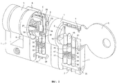
на фиг.1 - изображение в аксонометрии деталей, из которых состоит предлагаемый в изобретении замок,
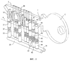
на фиг.2 - изображение в аксонометрии внутреннего устройства замка с местным вырывом и разрезом некоторых наружных деталей замка,
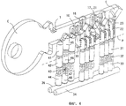
на фиг.3 и 4 - изображение в аксонометрии, соответственно в виде слева и справа только внутренних деталей замка,
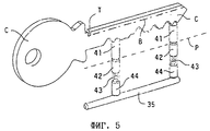
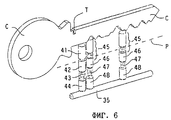
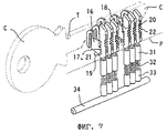
на фиг. 5, 6 и 7 - изображение в аксонометрии трех основных механизмов, из которых состоит замок,
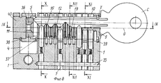
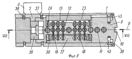
на фиг.8 - поперечное сечение замка центральной вертикальной продольной плоскостью VIII-VIII по фиг.9,
на фиг.9 - сечение замка горизонтальной плоскостью IX-IX по фиг.8,
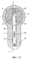
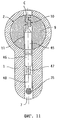
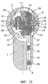
на фиг.10, 11 и 12 - соответственно сечения замка вертикальными плоскостями Х-Х, XI-XI и XI1-XII по фиг.8,
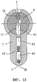
на фиг.13-16 - чертеж, поясняющий, каким образом предлагаемый в изобретении замок можно открыть и закрыть двумя различными ключами (индивидуальным ключом и мастер-ключом), и
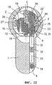
на фиг.17-22 - чертеж, поясняющий, каким образом осуществляется перепрограммирование предлагаемого замка с одного индивидуального ключа на другой.The above, as well as other distinctive features, objectives and advantages of the present invention are described in more detail below on a non-limiting example of one of the possible options for its implementation with reference to the accompanying drawings, which show:
figure 1 is a perspective view of the details of which the castle proposed in the invention consists,
figure 2 is a perspective view of the internal structure of the castle with a local breakout and a cut of some of the outer parts of the castle,
figure 3 and 4 - image in a perspective view, respectively, in the form of left and right only internal parts of the castle,
in FIG. 5, 6 and 7 - a perspective view of the three main mechanisms that make up the castle,
Fig.8 is a cross section of the castle of the Central vertical longitudinal plane VIII-VIII of Fig.9,
Fig.9 is a cross section of the castle by a horizontal plane IX-IX in Fig.8,
figure 10, 11 and 12, respectively, the cross section of the castle by the vertical planes XX, XI-XI and XI1-XII of Fig.8,
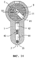
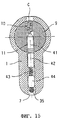
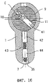
13-16 are a drawing explaining how the lock according to the invention can be opened and closed with two different keys (an individual key and a master key), and
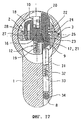
on Fig.17-22 is a drawing explaining how the reprogramming of the proposed lock is carried out from one individual key to another.
Предлагаемый в изобретении замок, один из вариантов выполнения которого показан на фиг.1, 2 и 8-12, имеет статор 1 с круглым поперечным сечением и расположенным в его нижней части вытянутым выступом, имеющим форму статора широко распространенных замков такого типа. Следует однако заметить, что предлагаемый в изобретении замок может иметь и другой по форме статор и что форма статора зависит от требований, которые определяются конкретными особенностями установки замка. Статор 1 имеет отверстие 2 для установки ротора 9, в котором по крайней мере в месте расположения программирующего механизма выполнена продольная канавка 3 (фиг.12). В рассматриваемом варианте замок имеет только одну канавку 3, которая проходит перпендикулярно отверстиям для установки запорных контр-штифтов, как более подробно описано ниже, однако такая конструкция не является единственно возможной, и в других вариантах замок может иметь две или больше таких канавок, расположенных под разными углами. Показанный на чертежах статор 1 имеет также прорезь 4, в которой расположено соединенное с ротором 9 кольцо 5 с радиальным выступом 6, которое служит управляющим элементом замка. Очевидно однако, что вместо такого кольца с радиальным выступом в качестве управляющего элемента замка можно использовать и другие устройства, например, эксцентриковый валик ключа, выступающий за задний конец ротора 9. Статор 1 имеет также вертикальные отверстия 7 и 8, в которых расположены запорные контр-штифты замка, как более подробно описано ниже. The lock according to the invention, one of the embodiments of which is shown in FIGS. 1, 2 and 8-12, has a
Ротор 9 замка цилиндрической формы имеет отверстие, в которое вставляется плоский ключ С, и удерживается в отверстии 2 статора пружинными кольцами 37 и 38 и разрезным пружинным кольцом 39, о котором подробнее сказано ниже. В рассматриваемом варианте замка помещенный внутрь статора 1 ротор 9 соединяется с имеющим радиальный выступ 6 кольцом 5 соединительным элементом 36, через который вращение ротора передается кольцу с радиальным выступом. Задний конец отверстия 2 статора закрыт имеющей соответствующую толщину заглушкой 40. The
Внутри статора 1 и ротора 9 расположены механизмы трех типов, которые показаны на фиг.5-7 и 10-12. Inside the
Механизм типа I (фиг.5 и 10) представляет собой обычный механизм с запорными штифтами и запорными контр-штифтами, который состоит из нескольких идентичных узлов, в каждом из которых имеется запорный штифт 41, вставленный в отверстие 11 ротора 9, которое пересекает отверстие 10 для плоского ключа С, а также контр-штифт 42, пружину 43 и упор 44, которые вставлены в отверстие 7 статора и удерживаются в нем вместе с другими аналогичными деталями замка удерживающим стержнем 35, который вставлен в продольное отверстие статора. Такой механизм сам по себе достаточно хорошо известен и позволяет повернуть ротор 9 относительно статора 1 только в том случае, когда высота зуба ключа С, который воздействует на запорный стержень 41, такова, что поверхность, разделяющая запорный стержень 41 от запорного контр-стержня 42, совпадет с цилиндрической поверхностью прилегания статора 1 к ротору 9 (линия Р на фиг. 5). В любом другом положении запорный штифт 41 или запорный контр-штифт 42 пересекает эту поверхность и образует в замке стопор, препятствующий повороту ротора 9. The type I mechanism (FIGS. 5 and 10) is a conventional mechanism with locking pins and locking counter pins, which consists of several identical nodes, each of which has a
Очень важно отметить, что такой обычный механизм типа I повышает надежность замка, увеличивая количество возможных комбинаций кодов ключа, и благодаря наличию стопора затрудняет открытие замка без соответствующего ключа, при этом однако наличие в замке такого механизма не создает возможностей ни для программирования замка, ни для его использования с мастер-ключами. Целесообразно предусмотреть в замке несколько таких простых в изготовлении и сборке механизмов; тем не менее предлагаемый в изобретении замок вообще может не иметь ни одного механизма типа I, поскольку по существу в нем, помимо механизма типа I, обязательно должны быть и другие соответствующие механизмы. It is very important to note that such a conventional type I mechanism increases the reliability of the lock by increasing the number of possible combinations of key codes, and thanks to the presence of a stopper, it makes it difficult to open the lock without the corresponding key, however, the presence of such a mechanism in the lock does not create opportunities for programming the lock, nor for its use with master keys. It is advisable to provide in the castle several such mechanisms that are simple to manufacture and assemble; nevertheless, the lock proposed in the invention may not have any type I mechanism at all, since essentially, in addition to the type I mechanism, there must necessarily be other corresponding mechanisms.
Механизм типа II (фиг.6 и 11) представляет собой обычный механизм замков с мастер-ключами. Этот механизм собирается в замке точно так же, как и механизм типа I, от которого он отличается тем, что его запорный штифт 45 вблизи поверхности, отделяющей его от запорного контр-штифта 46, разделен как минимум на две части. При наличии такого механизма типа II для того, чтобы повернуть ротор 9 относительно статора 1, высота зуба ключа С, который упирается в запорный штифт 45, должна быть такой, чтобы с цилиндрической поверхностью прилегания ротора 9 к статору 1 (линия Р на фиг.6) совпала любая из поверхностей, отделяющих запорный контр-штифт 46 от запорного штифта 45 или отделяющих друг от друга отдельные части запорного штифта 45. В любом другом положении либо часть запорного штифта 45, либо запорный контр-штифт 46 пересекают поверхность прилегания ротора к статору и образуют в замке стопор, препятствующий повороту ротора 9. Выполненный таким образом механизм типа II позволяет открыть замок несколькими ключами С с различной высотой соответствующего зуба, количество которых равно количеству частей, на которые разделен запорный штифт 45. The type II mechanism (FIGS. 6 and 11) is a conventional lock mechanism with master keys. This mechanism is assembled in the lock in the same way as the type I mechanism, from which it differs in that its
Работа механизма типа II показана на фиг.13-16, на которых изображен механизм, в котором запорный штифт 45 разделен на четыре части. На фиг.13 показан ключ С с такой высотой зуба, при которой с цилиндрической поверхностью прилегания ротора 9 к статору 1 оказывается совмещенной поверхность, отделяющая первую часть запорного штифта 45 от его второй части. Освободившийся ротор 9 можно легко повернуть в положение, показанное на фиг.14; при этом вместе с ротором поворачивается только первая часть запорного штифта 45, а его остальные части остаются неподвижными в отверстии запорного контр-штифта 46. На фиг.15 показан ключ С с такой высотой зуба, при которой с цилиндрической поверхностью прилегания ротора 9 к статору 1 оказывается совмещенной поверхность, отделяющая третью часть запорного штифта 45 от его четвертой части. Очевидно, что таким ключом можно легко повернуть освободившийся ротор 9 в положение, показанное на фиг.16; при этом вместе с ротором поворачиваются первые три части запорного штифта 45, а его четвертая часть остается неподвижной в отверстии запорного контр-штифта 46. Описанным выше способом в рассматриваемом примере для поворота ротора можно использовать также еще два ключа С с другой высотой зубьев. The operation of the type II mechanism is shown in FIGS. 13-16, which depict a mechanism in which the
Таким образом, путем соответствующего выбора количества и высоты отдельных частей запорного штифта каждого из имеющихся в замке механизмов типа II можно создать систему замков с мастер-ключами одного или нескольких уровней, с помощью которых можно открывать и закрывать определенное количество объединенных в группы замков, каждый из которых можно также открывать и закрывать индивидуальным ключом, который однако не подходит к остальным замкам данной группы. Thus, by appropriate selection of the number and height of the individual parts of the locking pin of each of the type II mechanisms in the lock, you can create a system of locks with master keys of one or several levels, with which you can open and close a certain number of locks combined into groups, each of which can also be opened and closed with an individual key, which however does not fit the rest of the locks in this group.
Разбив всю группу однотипных замков на отдельные подгруппы, можно создать систему замков с одним мастер-ключом верхнего уровня, которым можно открывать и закрывать все замки данной группы, и с несколькими мастер-ключами нижнего уровня, которые подходят к замкам только одной из подгрупп и не подходят к замкам остальных подгрупп. Следует подчеркнуть, что количество уровней в такой иерархической системе с мастер-ключами не ограничено двумя и может быть увеличено. By breaking the entire group of locks of the same type into separate subgroups, you can create a system of locks with one master key of the upper level, with which you can open and close all locks of this group, and with several master keys of the lower level that are suitable for locks of only one of the subgroups and not fit the locks of the remaining subgroups. It should be emphasized that the number of levels in such a hierarchical system with master keys is not limited to two and can be increased.
Предлагаемый в изобретении замок обязательно должен иметь как минимум один описанный выше механизм типа II, без которого невозможно создать замок, открываемый и закрываемый мастер-ключами, однако на практике предпочтителен вариант замка с несколькими такими механизмами. The lock proposed in the invention must have at least one type II mechanism described above, without which it is impossible to create a lock that can be opened and closed with master keys, however, in practice, a lock with several such mechanisms is preferable.
При описании устройства механизма типа II было сказано, что запорные штифты 45 должны быть выполнены из нескольких отдельных частей. В этой связи следует отметить, что такой же результат можно получить, выполнив из отдельных частей запорные контр-штифты. Иначе говоря, для получения необходимого эффекта (возможность использования мастер-ключей) безразлично, какие из штифтов (запорных 45 или контр-штифтов 46) выполнить из нескольких частей. When describing the type II mechanism device, it was said that the locking pins 45 should be made of several separate parts. In this regard, it should be noted that the same result can be obtained by performing locking counter-pins from individual parts. In other words, to obtain the desired effect (the ability to use master keys) it does not matter which of the pins (locking 45 or counter-pins 46) are made of several parts.
Предлагаемый в изобретении замок должен также иметь программирующий механизм или механизм типа III, не ограничивающий изобретения, пример выполнения которого описан ниже. The lock proposed in the invention should also have a programming mechanism or type III mechanism, not limiting the invention, an example of implementation of which is described below.
Механизм типа III (фиг.7 и 12) представляет собой программирующий механизм, который в рассматриваемом варианте по существу ничем не отличается от программирующего механизма, описанного в Европейском патенте 0226252. Для размещения в замке деталей этого механизма в роторе выполнены первые гнезда 12 (фиг. 8 и 9), которые пересекают отверстие 10, в которое вставляется плоский ключ С, вторые гнезда 13, которые расположены параллельно первым гнездам, а также первая и вторая прорези 14 и 15, которые расположены под прямым углом к упомянутым гнездам параллельно продольной оси ротора. Каждый из узлов программирующего механизма имеет пластинчатый толкатель 16, который с возможностью перемещения в продольном и поперечном направлении вставлен в одно из первых гнезд 12 ротора и взаимодействует с соответствующими зубьями вставленного в отверстие 10 ключа С. Пластинчатый толкатель 16, который имеет на одном конце выступы 17, а на противоположном конце - скользящий соединительный элемент 18, связан с отжимающей его (в показанном на чертеже положении) вверх пружиной 19. В одно из вторых гнезд 13 вставлен подвижный запорный штифт 20, который имеет несколько первых канавок, обращенных в сторону выступов 17 пластинчатого толкателя 16, и одну или несколько канавок, обращенных в другую по отношению к пластинчатому толкателю 16 сторону. В первую перпендикулярную гнездам прорезь 14 вставлен стопорный стержень 23, на котором имеется несколько выступов 24, обращенных в сторону вторых канавок 22 запорных штифтов 20, и один расположенный на другой стороне гладкий выступ 25, который взаимодействует с канавкой 3 статора. Стопорный стержень 23 связан с пружинами 26, которые отжимают его наружу от центральной оси замка. Во вторую перпендикулярную гнездам прорезь 15 вставлен переносящий стержень 27, который имеет несколько соединительных отверстий 28, в которые входят упомянутые выше скользящие соединительные элементы 18 пластинчатых толкателей 16, и один расположенный на его другой по отношению к толкателям стороне гладкий выступ 29, который соответствующим образом взаимодействует с упомянутой канавкой 3 статора. Переносящий стержень 27 связан с пружинами 30, которые отжимают его наружу от центральной оси замка. The type III mechanism (Figs. 7 and 12) is a programming mechanism, which in the present case is essentially no different from the programming mechanism described in European Patent 0226252. For placement of parts of this mechanism in the lock in the rotor, the
В отверстие 8 статора можно вставить запорный контр-штифт 31, взаимодействующий с запорным штифтом 20; этот контр-штифт нагружен пружиной 32, которая через элемент 33 упирается в удерживающий стержень 34, вставленный в соответствующее отверстие статора. Хотя такие запорные контр-штифты и повышают надежность замка, тем не менее их использование в рассматриваемом замке не является строго обязательным, поскольку блокировка ротора в закрытом положении может быть выполнена только одними запорными штифтами 20; в таком варианте из числа деталей, из которых состоит предлагаемый в изобретении замок, можно исключить не только сами запорные контр-штифты 31, но и соответствующие пружины 32, элементы 33 и удерживающий стержень 34. In the
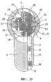
Рассмотренный выше программирующий механизм работает следующим образом (фиг.17-22). The above programming mechanism operates as follows (Fig.17-22).
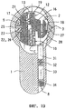
При отсутствии ключа (фиг.17) или при установке в замок ключа, который к нему не подходит, запорные штифты 20 и запорные контр-штифты 31 (последние - при их наличии в замке) пересекают поверхность прилегания ротора 9 к статору 1 и препятствуют повороту ротора. При этом запорные штифты 20, в канавки 21 которых входят выступы 17 пластинчатых толкателей 16, соединены с пластинчатыми толкателями. Под действием пружин 26 стопорный стержень 23, гладкий выступ 25 которого входит в канавку 3, прижимается к статору; при этом его выступы 24 не входят в канавки 22 запорных штифтов 20, которые при этом находятся в свободном положении и могут при установке в замок ключа или его извлечении из замка свободно перемещаться внутри замка соответствующими пластинчатыми толкателями 16. При установке в отверстие замка ключа, который подходит к замку (фиг.18), поверхность, отделяющая друг от друга концы запорных штифтов 20 и запорных контр-штифтов 31, совмещается с поверхностью прилегания ротора 9 к статору 1, после чего, повернув ротор на 360o, можно открыть замок. После поворота ротора на 360o, когда все его детали вернутся в исходное положение, ключ из замка можно вынуть.In the absence of a key (Fig. 17) or when a key is installed in the lock that does not fit it, locking pins 20 and locking counter pins 31 (the latter, if present in the lock) intersect the contact surface of the
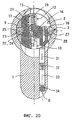
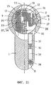
Для перепрограммирования замка его ротор нужно повернуть на 180o в показанное на фиг.19 положение замены ключа; при таком повороте ротора выступ 29 переносящего стержня 27 совместится с канавкой 3 статора и прижмется к ней под действием пружин 30, а соединенные друг с другом скользящим соединением элементы 18 и 28 переместят пластинчатые толкатели 16 в поперечном направлении и выведут выступы 17 толкателей из зацепления с канавками 21 запорных штифтов. При этом выступы 24 стопорного стержня 23, который при повороте ротора выйдет из канавки 3, войдут внутрь канавок 22 и заблокируют запорные штифты 20 в этом положении. Если в этом положении ключ С из замка вынуть, как более подробно описано ниже, то все пластинчатые толкатели 16 под действием пружин 19 опустятся в крайнее нижнее положение (фиг.20) и замок потеряет заложенную в него программу.To reprogram the lock, its rotor must be rotated 180 ° to the key replacement position shown in Fig. 19; with this rotation of the rotor, the
Вставив в замок новый ключ (фиг.21), можно переместить пластинчатые толкатели 16 в другое исходное положение и перепрограммировать тем самым замок на работу с этим новым ключом. После поворота ротора замка новым ключом на 180o перепрограммированный таким образом замок возвращается в исходное положение с сохранением новой заложенной в него новым ключом программы.Having inserted a new key into the lock (Fig. 21), it is possible to move the
Совершенно очевидно, что для такого перепрограммирования замка новый ключ должен подходить и к механизмам типа I (если они есть в замке) и к механизмам типа II, которые не являются программируемыми механизмами и не подлежат никакому видоизменению. It is quite obvious that for such a reprogramming of the lock, the new key must be suitable for both type I mechanisms (if they are in the lock) and type II mechanisms, which are not programmable mechanisms and are not subject to any modification.
Обычно не рекомендуется, чтобы любой владелец ключа от замка мог изменить заложенную в него программу. Для этого предлагаемый в изобретении замок выполняется таким образом, что после поворота ротора замка на 180o в положение замены ключа обычный ключ из замка вынуть нельзя, а можно вынуть только специальный отличающийся от обычного ключ, который собственно и предназначен для изменения заложенной в замок программы.It is usually not recommended that any owner of the key to the lock can change the program embedded in it. For this purpose, the lock proposed in the invention is made in such a way that after turning the lock rotor 180 ° to the key replacement position, the ordinary key cannot be removed from the lock, but only a special key different from the usual one can be removed, which is actually intended to change the program embedded in the lock.
С этой целью замок снабжен разрезным пружинным кольцом 39, которое вставляется в канавку 47, выполненную на наружной поверхности ротора 9 у его переднего края, и которое при установке ротора 9 в отверстие 2 статора 1 входит в соответствующую канавку 48, выполненную внутри по периметру отверстия 2, и остается неподвижным при повороте ротора. Разрезное пружинное кольцо 39 перекрывает отверстие 10, в которое вставляется ключ, и мешает свободному повороту ротора 9 с вставленным в замок ключом из исходного положения. Для возможности поворота ключа С на ключе рядом с его ручкой выполнена соответствующая канавка Т, которая однако при совмещении с разрезным пружинным кольцом 39 после поворота ключа С на 180o не позволяет вынуть ключ из замка.To this end, the lock is equipped with a
Ключ, предназначенный для перепрограммирования замка, имеет меньшую, чем обычный ключ высоту, как показано, например, пунктирной линией В на фиг.5. Такой ключ, которому не мешает разрезное пружинное кольцо 39, можно легко вынуть из ротора 9 после поворота на 180o, после чего в отверстие замка можно вставить по-другому закодированный ключ с аналогичным образом уменьшенной высотой и изменить заложенную в замок программу.The key for reprogramming the lock has a lower height than a conventional key, as shown, for example, by the dashed line B in FIG. 5. Such a key, which does not interfere with the
Специальную форму, которая позволяет менять заложенную в замок программу, могут иметь все мастер-ключи, часть мастер-ключей или только один специальный мастер-ключ, с помощью которого можно менять заложенную в замок программу. All master keys, part of the master keys or only one special master key with which you can change the program locked in the lock can have a special form that allows you to change the program embedded in the lock.
Следует подчеркнуть, что несмотря на сложность конструкции предлагаемого замка его промышленное изготовление не представляет больших сложностей и позволяет достичь определенных преимуществ. Кроме того, перепрограммирование замка, которое может быть выполнено самим пользователем, отличается предельной простотой и в то же самое время обеспечивает максимальную надежность замка. Конструкция замка позволяет использовать для работы с ним большое количество самых разных ключей. Замок несмотря на высокую точность изготовления его механизмов обладает достаточно большой прочностью. С целью в еще большей степени повысить надежность замка и защитить его от возможного вскрытия с помощью дрели или другого аналогичного инструмента в ротор 9 можно запрессовать несколько специальных штифтов 49, изготовленных из очень твердого материала. It should be emphasized that despite the complexity of the design of the proposed castle, its industrial production does not present great difficulties and allows to achieve certain advantages. In addition, the reprogramming of the lock, which can be performed by the user himself, is extremely simple and at the same time ensures maximum reliability of the lock. The design of the lock allows you to use a large number of different keys to work with it. The castle, despite the high precision of manufacturing of its mechanisms, has a sufficiently high strength. In order to further increase the reliability of the lock and protect it from possible opening with a drill or other similar tool, several special pins 49 made of very hard material can be pressed into the
Необходимо отметить, что рассмотренный выше вариант конструкции замка является лишь примером возможного выполнения изобретения и никак не ограничивает объем изобретения. Помимо некоторых возможных изменений, о которых уже было сказано выше, в рассмотренную выше конструкцию замка могут быть внесены и другие очевидные для специалистов изменения. Так, в частности, на статоре замка вместо одной канавки для стопорного стержня и переносящего стержня можно выполнить несколько расположенных под разными углами канавок, позволяющих увеличить количество положений ротора, в которых осуществляется изменение программы и замена ключей, которыми открывается и закрывается замок. Такие, а также и другие изменения конструкции предлагаемого в изобретении замка или замена тех или иных используемых в нем устройств на эквивалентные не должны нарушать основной идеи изобретения и не должны выходить за его рамки, ограниченные приложенной к описанию формулой изобретения. It should be noted that the above design variant of the castle is only an example of a possible implementation of the invention and does not limit the scope of the invention. In addition to some possible changes, which have already been mentioned above, other obvious changes for specialists can be made to the castle design discussed above. So, in particular, on the lock stator, instead of one groove for the locking rod and the transferring rod, several grooves located at different angles can be made to increase the number of rotor positions in which the program is changed and the keys are replaced with which the lock opens and closes. Such, as well as other changes in the design of the lock proposed in the invention or the replacement of various devices used in it with equivalent ones should not violate the main idea of the invention and should not go beyond its scope limited by the claims attached to the description.
Claims (6)
Applications Claiming Priority (4)
| Application Number | Priority Date | Filing Date | Title |
|---|---|---|---|
| ITT097A000192 | 1997-03-10 | ||
| ITTO97A000192 | 1997-03-10 | ||
| IT97TO000192 IT1291177B1 (en) | 1997-03-10 | 1997-03-10 | PROGRAMMABLE CYLINDER LOCK, PROVIDED WITH MASTER KEYS. |
| US09/035,782 US6119495A (en) | 1997-03-10 | 1998-03-06 | Programmable cylinder lock, provided with master keys |
Publications (2)
| Publication Number | Publication Date |
|---|---|
| RU98122216A RU98122216A (en) | 2000-10-27 |
| RU2184197C2 true RU2184197C2 (en) | 2002-06-27 |
Family
ID=26332343
Family Applications (1)
| Application Number | Title | Priority Date | Filing Date |
|---|---|---|---|
| RU98122216A RU2184197C2 (en) | 1997-03-10 | 1998-03-03 | Programmable cylindrical lock provided with master-keys |
Country Status (34)
| Country | Link |
|---|---|
| US (1) | US6119495A (en) |
| EP (1) | EP0900310B1 (en) |
| JP (1) | JP4073498B2 (en) |
| CN (1) | CN1194160C (en) |
| AT (1) | ATE242392T1 (en) |
| AU (1) | AU735251B2 (en) |
| BG (1) | BG63512B1 (en) |
| BR (1) | BR9804774A (en) |
| CA (1) | CA2254400C (en) |
| CO (1) | CO4780050A1 (en) |
| CZ (1) | CZ295588B6 (en) |
| DE (1) | DE69815234T2 (en) |
| DK (1) | DK0900310T3 (en) |
| EG (1) | EG20941A (en) |
| ES (1) | ES2200331T3 (en) |
| HK (1) | HK1019909A1 (en) |
| HR (1) | HRP980128B1 (en) |
| HU (1) | HU222413B1 (en) |
| ID (1) | ID22088A (en) |
| IL (1) | IL126794A (en) |
| IT (1) | IT1291177B1 (en) |
| MA (1) | MA24479A1 (en) |
| NO (1) | NO331257B1 (en) |
| NZ (1) | NZ332743A (en) |
| PL (1) | PL186481B1 (en) |
| PT (1) | PT900310E (en) |
| RU (1) | RU2184197C2 (en) |
| SI (1) | SI0900310T1 (en) |
| SK (1) | SK285526B6 (en) |
| TR (1) | TR199802283T1 (en) |
| TW (1) | TW590141U (en) |
| UA (1) | UA61909C2 (en) |
| WO (1) | WO1998040589A1 (en) |
| ZA (1) | ZA981968B (en) |
Families Citing this family (78)
| Publication number | Priority date | Publication date | Assignee | Title |
|---|---|---|---|---|
| AUPP572498A0 (en) * | 1998-09-04 | 1998-10-01 | Australian Lock Company Pty Ltd | Moveable element lock and key |
| KR200179707Y1 (en) * | 1999-12-10 | 2000-04-15 | 김정규 | A lock construction |
| JP3709146B2 (en) * | 2000-03-09 | 2005-10-19 | 株式会社アルファ | Cylinder lock |
| US6604393B2 (en) * | 2001-07-11 | 2003-08-12 | Tri/Mark Corporation | Lock system operable with multiple keys |
| AUPR838901A0 (en) * | 2001-10-19 | 2001-11-15 | Cylock Pty Ltd | Improved security lock |
| AU2002332964B2 (en) * | 2001-10-19 | 2005-07-21 | Cylock Pty Ltd | Security lock supporting master keying |
| AUPR838701A0 (en) * | 2001-10-19 | 2001-11-15 | Cylock Pty Ltd | Improved lock |
| US6776017B2 (en) | 2001-11-08 | 2004-08-17 | Ez Change Lock Company, Llc | Adaptable radial tumbler lock |
| US7634930B2 (en) * | 2002-01-03 | 2009-12-22 | Strattec Security Corporation | Lock apparatus and method |
| MXPA04006854A (en) * | 2002-01-03 | 2005-06-17 | Strattec Security Corp | Vehicular lock apparatus and method. |
| DK1523603T3 (en) * | 2002-07-24 | 2006-12-04 | Ernst Keller | Security key and lock cylinder |
| US8347678B2 (en) * | 2002-09-26 | 2013-01-08 | Newfrey, Llc | Rekeyable lock cylinder assembly |
| US6959569B2 (en) * | 2002-09-26 | 2005-11-01 | Newfrey Llc | Re-keyable lock assembly |
| US6860131B2 (en) * | 2002-09-26 | 2005-03-01 | Newfrey Llc | Rekeying a lock assembly |
| US7114357B2 (en) * | 2002-09-26 | 2006-10-03 | Newfrey, Llc | Keying system and method |
| US6862909B2 (en) * | 2002-09-26 | 2005-03-08 | Newfrey Llc | Devices, methods, and systems for keying a lock assembly |
| JP3776078B2 (en) * | 2002-10-15 | 2006-05-17 | タキゲン製造株式会社 | Sidebar type variable code cylinder lock |
| BRPI0408088B1 (en) * | 2003-03-04 | 2015-07-07 | Kwikset Corp | Lock drum that may have new secret and method of keying a lock drum |
| US6951123B2 (en) * | 2003-03-05 | 2005-10-04 | Newfrey Llc | Rekeyable lock |
| AU2003903029A0 (en) * | 2003-06-16 | 2003-07-03 | Predesign Pty Ltd | Rotary lock and key |
| US6973813B2 (en) * | 2003-12-05 | 2005-12-13 | Newfrey Llc | Re-keyable lock and method |
| CN2670535Y (en) * | 2003-12-22 | 2005-01-12 | 狮城科技园(苏州)有限公司 | Lock with replaceable key |
| US7007528B2 (en) * | 2004-04-01 | 2006-03-07 | Newfrey Llc | Re-keyable lock cylinder |
| US7162901B2 (en) * | 2004-04-01 | 2007-01-16 | Newfrey Llc | Variable shear line lock cylinder |
| US20060059965A1 (en) * | 2004-09-17 | 2006-03-23 | Benstead Evan A | Rekeyable lock having 2-piece pin with rotatable member |
| US20060101880A1 (en) * | 2004-11-12 | 2006-05-18 | Ward-Dolkas Paul C | Re-keyable lock cylinder |
| WO2006066019A2 (en) * | 2004-12-14 | 2006-06-22 | Stanley Security Solutions, Inc. | Key core |
| US20060185404A1 (en) * | 2005-02-18 | 2006-08-24 | Hansen Randall C | Codeable padlock |
| US7340929B1 (en) | 2005-03-21 | 2008-03-11 | Efthemois Christopoulos | Axially rotative rekeyable lock |
| ITMI20051507A1 (en) | 2005-08-01 | 2007-02-02 | Giussani Tech S P A | REPROGRAMMABLE LOCK |
| CN2818692Y (en) * | 2005-09-09 | 2006-09-20 | 玛拉峰电子(苏州)有限公司 | Multifunctional lock |
| US8881567B2 (en) * | 2005-10-21 | 2014-11-11 | Kwikset Corporation | Reset fixture for rekeyable lock assembly |
| JP4850608B2 (en) * | 2006-07-28 | 2012-01-11 | 株式会社アルファ | Cylinder lock |
| TW200900569A (en) * | 2007-06-25 | 2009-01-01 | Taiwan Fu Hsing Ind Co Ltd | A lock core capable of swiftly changing keys and the key changing method thereof |
| TW200844314A (en) * | 2007-05-11 | 2008-11-16 | Taiwan Fu Hsing Ind Co Ltd | Lock cylinder fitting to different keys and method for fitting a lock cylinder with different keys |
| US7424815B1 (en) * | 2007-06-12 | 2008-09-16 | Giussani Techniques S.P.A. | Reprogrammable lock |
| CN101743367B (en) * | 2007-06-13 | 2013-06-26 | 施拉格锁业公司 | Programmable lock cylinder assembly |
| US8621902B2 (en) | 2007-06-13 | 2014-01-07 | Schlage Lock Company Llc | Master keying system and method for programmable lock cylinder assemblies |
| TWI345602B (en) * | 2007-06-15 | 2011-07-21 | Taiwan Fu Hsing Ind Co Ltd | Rekeyable lock cylinder structure ,plug assembly thereof,plug body of plug assembly,sliding block of plug assembly ,structured lower pins of pin groups and cylinder body |
| TWI340784B (en) * | 2007-09-26 | 2011-04-21 | Taiwan Fu Hsing Ind Co Ltd | A method for a rekeyable lock cylinder |
| US7624606B1 (en) * | 2008-05-07 | 2009-12-01 | Taiwan Fu Hsing Industrial Co., Ltd. | Rekeyable lock cylinder, plug assembly of the same and method for rekeying the same |
| US7937976B2 (en) * | 2008-05-07 | 2011-05-10 | Taiwan Fu Hsing Industrial Co., Ltd. | Rekeyable lock cylinder and operating method thereof |
| US8448484B2 (en) * | 2008-05-07 | 2013-05-28 | Taiwan Fu Hsing Industrial Co., Ltd. | Rekeyable lock cylinder |
| US7628048B2 (en) * | 2008-05-07 | 2009-12-08 | Taiwan Fu Hsing Industrial Co., Ltd. | Rekeyable lock cylinder and method for rekeying the same |
| TWI372201B (en) * | 2008-05-12 | 2012-09-11 | Taiwan Fu Hsing Ind Co Ltd | Rekeyable lock cylinder, plug assembly of the same and method for rekeying the same |
| ES2331864B1 (en) * | 2008-07-15 | 2010-10-28 | Salto Systems, S.L. | ELECTROMECHANICAL CYLINDER FOR LOCK. |
| AU2009212832A1 (en) * | 2008-08-29 | 2010-03-18 | Tong Lung Metal Industry Co., Ltd. | Re-Keyable Cylinder Lock |
| CN101684700B (en) * | 2008-09-25 | 2012-06-13 | 台湾福兴工业股份有限公司 | Replaceable key lock core with foolproof function |
| US8001816B2 (en) * | 2008-11-11 | 2011-08-23 | Carl Black | Pin tumbler lock releasing system |
| TWM371150U (en) * | 2009-05-27 | 2009-12-21 | zheng-ru Yang | Improved spindle for disc-tumbler lock cylinder |
| DE102009030032A1 (en) * | 2009-06-23 | 2010-12-30 | ABUS August Bremicker Söhne KG | Platelet cylinder with lockable platelet tumblers |
| US8739587B2 (en) * | 2009-08-18 | 2014-06-03 | Kwikset Corporation | Rekeyable lock assembly with blown cylinder protection |
| IT1397790B1 (en) * | 2010-01-25 | 2013-01-24 | Rielda Serrature Srl | PROGRAMMABLE CYLINDER LOCK WITH A HIGH NUMBER OF COMBINATIONS. |
| IT1398397B1 (en) * | 2010-01-27 | 2013-02-22 | Rielda Serrature Srl | PROGRAMMABLE CYLINDER LOCK THAT DOES NOT REQUIRE A SPECIAL CHANGE KEY |
| IT1397986B1 (en) * | 2010-02-10 | 2013-02-04 | Rielda Serrature Srl | PROGRAMMABLE CYLINDER LOCK WITH A CHANGED CHANGE POSITION |
| US8490446B2 (en) | 2010-04-23 | 2013-07-23 | Schlage Lock Company | Programmable lock cylinder assembly |
| IT1399813B1 (en) | 2010-04-27 | 2013-05-03 | Rielda Serrature Srl | PROGRAMMABLE CYLINDER LOCK WITH CODIFICATION PROTECTION DEVICE, AND KEYS FOR ITS MANEUVER. |
| IT1400162B1 (en) | 2010-05-06 | 2013-05-17 | Rielda Serrature Srl | PERFECT PROGRAMMABLE CYLINDER LOCK, AND KEYS FOR ITS MANEUVER |
| US7980104B1 (en) * | 2010-05-19 | 2011-07-19 | Taiwan Fu Hsing Industrial Co., Ltd. | Rekeyable lock cylinder |
| US8099988B1 (en) | 2010-08-09 | 2012-01-24 | Newfrey, Llc | Tool-less rekeyable lock cylinder |
| US8291735B1 (en) | 2011-03-31 | 2012-10-23 | Newfrey, Llc | Rekeyable lock cylinder having rotatable key followers |
| WO2013011527A1 (en) * | 2011-07-15 | 2013-01-24 | Cisa S.P.A. | Rekeyable cylinder |
| US9657499B2 (en) * | 2011-10-10 | 2017-05-23 | Spectrum Brands, Inc. | Method and apparatus for a rekeyable master key lock |
| US8950226B2 (en) * | 2011-10-12 | 2015-02-10 | Moshe Dolev | Cylinder lock assembly with non-rotating elements |
| CN103179830A (en) * | 2011-12-24 | 2013-06-26 | 富泰华工业(深圳)有限公司 | Push device |
| ITBO20120662A1 (en) | 2012-12-10 | 2014-06-11 | Filippo Bastianini | LOCK WITH MECHANICALLY REPROGRAMMABLE DISK LOCK AND KEY FOR THE SAME |
| DE102012025536A1 (en) * | 2012-12-14 | 2014-06-18 | Assa Abloy Sicherheitstechnik Gmbh | Key trigger lock |
| US9512642B2 (en) * | 2014-03-07 | 2016-12-06 | Keyless.Co, Llc | Reprogrammable cylinder lock |
| CN103899150B (en) * | 2014-03-27 | 2016-03-30 | 宁波市鄞州剑均机械科技有限公司 | The combination of a kind of tapered end and key |
| EP2993284A1 (en) * | 2014-08-26 | 2016-03-09 | DORMA Deutschland GmbH | Cylinder body for a cylinder for locks |
| CN104405215A (en) * | 2014-11-21 | 2015-03-11 | 徐浩钟 | Asynchronous mechanical antitheft locking lock |
| ES1135888Y2 (en) * | 2015-01-22 | 2021-06-02 | Talleres Escoriaza Sa | Lock key with compatible activation stop |
| IT201600114296A1 (en) * | 2016-11-11 | 2018-05-11 | Mg Serrature S P A | HIGH SAFETY LOCKING DEVICE |
| CN108071270B (en) * | 2017-12-12 | 2019-07-23 | 嘉兴美可泰科技有限公司 | Tamper-proof precision machinery turns twistlock head safety anti-theft lock |
| US11319726B2 (en) | 2018-10-22 | 2022-05-03 | Spectrum Brands, Inc. | Tool-less rekeyable lock cylinder |
| CA3119353C (en) * | 2018-12-07 | 2023-07-25 | Winloc Ag | A cylinder lock unit and an associated key |
| CN112537557B (en) * | 2021-01-06 | 2022-04-12 | 滨州学院 | Be applied to aviation container that aviation loaded |
| IT202100005276A1 (en) | 2021-03-05 | 2022-09-05 | Rielda Serrature S P A | PROGRAMMABLE CYLINDER LOCK THAT DOES NOT REQUIRE A SPECIAL KEY TO CHANGE |
Family Cites Families (16)
| Publication number | Priority date | Publication date | Assignee | Title |
|---|---|---|---|---|
| US3999413A (en) * | 1975-01-31 | 1976-12-28 | Raymond James W | Lock assembly |
| US4015458A (en) * | 1975-11-21 | 1977-04-05 | Leonard Mercurio | Wafer type tumbler lock construction having individual side bar tumbler inhibiting means |
| US4028917A (en) * | 1976-04-12 | 1977-06-14 | Schlage Lock Company | Key retaining cylinder for a lock |
| FR2410718A1 (en) * | 1977-12-05 | 1979-06-29 | Initial | Anti-picking mechanism for cylinder lock - uses nominal rotor rotation to move sliding pin and jam locking bit |
| SE422480B (en) * | 1979-07-10 | 1982-03-08 | Gkn Stenman Ab | CYLINDERLESS KEY TO THIS AND MANUFACTURING THE KEY |
| US4376382A (en) * | 1980-12-01 | 1983-03-15 | James W. Raymond | Resettable lock assembly |
| US4741188A (en) * | 1985-07-16 | 1988-05-03 | Smith Jerry R | Rekeyable master and user lock system with high security features |
| IT1208841B (en) * | 1985-12-19 | 1989-07-10 | Rielda Serrature Srl | CYLINDER LOCK WITH INTERCHANGEABLE KEY |
| US4729231A (en) * | 1986-12-29 | 1988-03-08 | Wu Tsay D | Changeable key type lock barrel |
| US4912953A (en) * | 1988-09-29 | 1990-04-03 | National Lock Corporation | Re-keyable cylinder lock |
| US4966021A (en) * | 1988-11-04 | 1990-10-30 | Masco Building Products Corp. | Reprogrammable lock and keys therefor |
| US5079936A (en) * | 1989-03-31 | 1992-01-14 | Folger Adam Company | High security cylinder lock |
| US4942749A (en) * | 1989-06-26 | 1990-07-24 | Jacob Rabinow | Interchangeable key lock with rolling tumblers |
| US5000019A (en) * | 1989-08-07 | 1991-03-19 | Foster Merle L | Cylinder lock and method for using same |
| AU672303B2 (en) * | 1994-07-01 | 1996-09-26 | Brian Arthur Cook | A key operable locking mechanism |
| AT405669B (en) * | 1995-03-03 | 1999-10-25 | Evva Werke | DRILL LOCK FOR CYLINDER LOCKS |
-
1997
- 1997-03-10 IT IT97TO000192 patent/IT1291177B1/en active IP Right Grant
-
1998
- 1998-01-26 EG EG9498A patent/EG20941A/en active
- 1998-02-18 MA MA24970A patent/MA24479A1/en unknown
- 1998-03-03 TR TR1998/02283T patent/TR199802283T1/en unknown
- 1998-03-03 ID ID980128D patent/ID22088A/en unknown
- 1998-03-03 WO PCT/EP1998/001295 patent/WO1998040589A1/en active IP Right Grant
- 1998-03-03 DE DE1998615234 patent/DE69815234T2/en not_active Expired - Lifetime
- 1998-03-03 AU AU68285/98A patent/AU735251B2/en not_active Ceased
- 1998-03-03 CA CA 2254400 patent/CA2254400C/en not_active Expired - Fee Related
- 1998-03-03 IL IL12679498A patent/IL126794A/en not_active IP Right Cessation
- 1998-03-03 NZ NZ33274398A patent/NZ332743A/en unknown
- 1998-03-03 SI SI9830498T patent/SI0900310T1/en unknown
- 1998-03-03 CN CNB988006189A patent/CN1194160C/en not_active Expired - Fee Related
- 1998-03-03 EP EP98913669A patent/EP0900310B1/en not_active Expired - Lifetime
- 1998-03-03 DK DK98913669T patent/DK0900310T3/en active
- 1998-03-03 RU RU98122216A patent/RU2184197C2/en not_active IP Right Cessation
- 1998-03-03 PL PL98329721A patent/PL186481B1/en not_active IP Right Cessation
- 1998-03-03 ES ES98913669T patent/ES2200331T3/en not_active Expired - Lifetime
- 1998-03-03 BR BR9804774A patent/BR9804774A/en not_active IP Right Cessation
- 1998-03-03 HU HU0001502A patent/HU222413B1/en not_active IP Right Cessation
- 1998-03-03 AT AT98913669T patent/ATE242392T1/en active
- 1998-03-03 PT PT98913669T patent/PT900310E/en unknown
- 1998-03-03 JP JP53919298A patent/JP4073498B2/en not_active Expired - Fee Related
- 1998-03-03 UA UA98126511A patent/UA61909C2/en unknown
- 1998-03-03 SK SK1686-98A patent/SK285526B6/en not_active IP Right Cessation
- 1998-03-03 CZ CZ19984070A patent/CZ295588B6/en not_active IP Right Cessation
- 1998-03-06 US US09/035,782 patent/US6119495A/en not_active Expired - Lifetime
- 1998-03-09 CO CO98012794A patent/CO4780050A1/en unknown
- 1998-03-09 ZA ZA981968A patent/ZA981968B/en unknown
- 1998-03-10 HR HR980128A patent/HRP980128B1/en not_active IP Right Cessation
- 1998-07-10 TW TW91218681U patent/TW590141U/en not_active IP Right Cessation
- 1998-10-26 NO NO984990A patent/NO331257B1/en not_active IP Right Cessation
- 1998-12-09 BG BG103004A patent/BG63512B1/en unknown
-
1999
- 1999-11-05 HK HK99105061A patent/HK1019909A1/en not_active IP Right Cessation
Also Published As
Similar Documents
| Publication | Publication Date | Title |
|---|---|---|
| RU2184197C2 (en) | Programmable cylindrical lock provided with master-keys | |
| RU2120015C1 (en) | Disk cylinder lock and its key | |
| US8117876B2 (en) | Programmable lock cylinder assembly | |
| US7181937B2 (en) | Locking cylinder | |
| US4185480A (en) | Key-operated pin tumbler lock | |
| EP0903455B1 (en) | Effraction-resistant device for a lock with flat tumblers | |
| US10570643B2 (en) | Cylinder lock core for a cylinder lock unit | |
| EP1752601B1 (en) | Reprogrammable lock | |
| PL188350B1 (en) | Cylinder lock | |
| CN111577011B (en) | Lock cylinder and key system | |
| US20040237612A1 (en) | Lock with cylinder incorporating laterally biased bar engaging corresponding key | |
| KR100538363B1 (en) | Programmable cylinder lock with master key. | |
| US4796447A (en) | Lock with key isolation using transfer tumblers | |
| KR840001430B1 (en) | A cylinder lock a key for the lock and a method of manufacturing | |
| MXPA98008673A (en) | A programmable cylinder lock, provided with master keys | |
| RU2151253C1 (en) | Code insert | |
| KR20210127139A (en) | Cylinder locking unit and key associated therewith | |
| RU2146751C1 (en) | Coded lock | |
| JP2002357032A (en) | Composite cylinder key | |
| GB2064637A (en) | Cylinder Lock | |
| HU224561B1 (en) | Cylinder lock with replaceable plug | |
| AU2002332963A1 (en) | Lock with cylinder incorporating laterally biased bar engaging corresponding key |
Legal Events
| Date | Code | Title | Description |
|---|---|---|---|
| MM4A | The patent is invalid due to non-payment of fees |
Effective date: 20140304 |