RU2178373C1 - Aircraft manual control system - Google Patents
Aircraft manual control system Download PDFInfo
- Publication number
- RU2178373C1 RU2178373C1 RU2000132890A RU2000132890A RU2178373C1 RU 2178373 C1 RU2178373 C1 RU 2178373C1 RU 2000132890 A RU2000132890 A RU 2000132890A RU 2000132890 A RU2000132890 A RU 2000132890A RU 2178373 C1 RU2178373 C1 RU 2178373C1
- Authority
- RU
- Russia
- Prior art keywords
- control
- handle
- aircraft
- disconnect
- rod
- Prior art date
Links
- 239000000126 substance Substances 0.000 abstract 1
- 238000010586 diagram Methods 0.000 description 1
- 238000005516 engineering process Methods 0.000 description 1
- 238000000034 method Methods 0.000 description 1
Images
Landscapes
- Mechanical Control Devices (AREA)
Abstract
Description
Изобретение относится к области авиационной техники, в частности к системам ручного управления самолетом, и предназначено для реализации на воздушных судах любого назначения. Система позволяет отключать одну из ручек управления самолетом (РУС) от пилотирования с тем, чтобы использовать ее для управления бортовым оборудованием при сохранении возможности обратного подключения ее к пилотированию. The invention relates to the field of aviation technology, in particular to systems for manual control of an aircraft, and is intended for sale on aircraft of any purpose. The system allows you to disconnect one of the aircraft control sticks (RUS) from piloting in order to use it to control on-board equipment while maintaining the possibility of reconnecting it to piloting.
Известна ручка управления самолетом для второго пилота с возможностью ее отключения от пилотирования самолета (патент US N 4473203, кл. США 244-224, 244-229), которая связана с ручкой управления самолетом первого пилота соединением, вынуждающим эти две ручки управления оставаться параллельными в процессе пилотирования. Это соединение включает в себя два параллельных стержня, образующих с осями ручек управления деформируемый параллелограмм. Один из стержней концами соединен с центрами шарниров ручек, является валом кручения и способен поворачиваться относительно этих шарниров. Другой стержень является шатуном, работающим на растяжение или сжатие. Ручка второго пилота соединена со стержнями двойным универсальным шарниром, включающим внешнее кольцо и внутреннее кольцо. Внешнее кольцо соединено с одной стороны со стержнем-валом, а с другой стороны - с элементом, жестко соединенным со стержнем шатуном. Вторая ручка управления связана с упомянутым элементом особым устройством захвата, которое делает возможным закрепить вторую ручку управления и внешнее кольцо к двойному универсальному шарниру или отсоединять ее. Known aircraft control stick for the second pilot with the ability to disconnect it from piloting the aircraft (US patent N 4473203, CL. USA 244-224, 244-229), which is connected with the control handle of the aircraft of the first pilot connection, forcing these two control sticks to remain parallel in piloting process. This connection includes two parallel rods forming a deformable parallelogram with the axes of the control knobs. One of the rods is connected by ends to the centers of the hinges of the handles, is a torsion shaft and is capable of turning relative to these hinges. The other rod is a tensile or compressive connecting rod. The handle of the second pilot is connected to the rods by a double universal joint, including the outer ring and inner ring. The outer ring is connected on one side to the shaft-shaft, and on the other hand, to an element rigidly connected to the rod by a connecting rod. The second control handle is connected to the said element with a special gripping device, which makes it possible to fix the second control handle and the outer ring to a double universal joint or disconnect it.
Недостатком данного механизма является то, что эта система отключения не обеспечивает возможности управления бортовым оборудованием с отключенной ручкой управления самолетом, а также то, что отключение/подключение второй ручки может осуществить только второй пилот. The disadvantage of this mechanism is that this shutdown system does not provide the ability to control on-board equipment with the airplane control stick turned off, and also that only the second pilot can disconnect / connect the second handle.
Прототипом может служить система ручного управления самолетом (патент RU 2015064, B 64 C 13/12), состоящая из двух постов управления в виде ручек управления и механизма отключения, соединенного с ручками шарнирными тягами. Она обеспечивает одновременное управление: один член экипажа пилотирует самолет, а другой управляет бортовым оборудованием с помощью отключенной от пилотирования второй ручкой управления самолетом. Сохраняется возможность ее подключения к пилотированию при необходимости взять управление пилотированием самолета на себя. Механизм отключения выполнен в виде поворотного относительно вертикальной оси корпуса, конец которого шарнирно соединен с одной из тяг, и подпружиненного пневмоцилиндра, расположенного внутри корпуса с возможностью перемещения цилиндра вдоль штока с поршнем, соединенного с другим концом корпуса, связанного с другой тягой ручки управления. The prototype can be a manual aircraft control system (patent RU 2015064, B 64
Недостатком данного механизма является зависимость его работы от наличия в кабине самолета сжатого воздуха, при сбое системы подачи сжатого воздуха отключение одной из ручек управления самолетом невозможно. The disadvantage of this mechanism is the dependence of its operation on the presence of compressed air in the aircraft cockpit; in case of a failure in the compressed air supply system, it is impossible to turn off one of the aircraft control knobs.
Задачей изобретения является обеспечение возможности отключения одной из рукояток управления самолетом от пилотирования независимо от наличия сжатого воздуха или другой энергосистемы в кабине воздушного судна при сохранении возможности работы отключенной от пилотирования ручкой управления с бортовым оборудованием самолета и сохранении возможности подключения при необходимости второй ручки управления самолетом к пилотированию. The objective of the invention is to enable one of the aircraft control handles to be disconnected from piloting regardless of the presence of compressed air or another power system in the aircraft cabin while maintaining the ability to operate the control handle disconnected from piloting with the aircraft's onboard equipment and maintaining the possibility of connecting, if necessary, a second aircraft control handle to pilot .
Задача решается с помощью системы ручного управления самолетом, состоящей из двух постов управления в виде неотключаемой и отключаемой ручек управления и механизма отключения, соединенного с каждой из ручек управления шарнирными тягами, отличающейся тем, что механизм отключения состоит из корпуса, закрепленного с возможностью вращения на неподвижной относительно самолета оси и соединенного шарнирно с тягой, ведущей к неотключаемой ручке управления, штока, перемещающегося внутри корпуса перпендикулярно упомянутой оси и соединенного шарниром с ведущей к отключаемой ручке управления тягой и со звеном, которое в другой своей точке соединено шарнирно с рычагом отключения/подключения. The problem is solved using the manual control system of the aircraft, consisting of two control stations in the form of non-disconnectable and disconnectable control knobs and a disconnect mechanism connected to each of the control rods of articulated rods, characterized in that the disconnect mechanism consists of a housing fixed for rotation on a fixed relative to the axis of the plane and pivotally connected with a thrust leading to a non-disconnectable control handle, a rod moving inside the housing perpendicular to the axis and connected arnirom with disconnectable leading to the control handle and to the link rod, which in its other point pivotally connected with the disconnection / connection arm.
Рычаг отключения/подключения может быть соединен с ручкой отключения/подключения. The disconnect / connect lever can be connected to the disconnect / connect knob.
Указанное выполнение позволяет фиксировать вторую ручку управления в положении, в котором ее ось неподвижна, т. е. на нее не передается движение первой ручки управления и от нее не передается движение к первой ручке. В таком положении управление бортовым оборудованием осуществляется с помощью элементов управления, установленных на второй ручке. The specified embodiment allows you to fix the second control handle in a position in which its axis is stationary, that is, the movement of the first control handle is not transmitted to it and the movement to the first handle is not transmitted from it. In this position, the onboard equipment is controlled using controls mounted on the second handle.
Изобретение поясняется чертежами. The invention is illustrated by drawings.
На фиг. 1 изображена конструктивная схема системы ручного управления самолетом. In FIG. 1 shows a structural diagram of a manual aircraft control system.
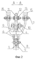
На фиг. 2 показано сечение А-А, поясняющее положение элементов системы при подключенной второй ручке управления самолетом. In FIG. 2 shows a section AA illustrating the position of the elements of the system when the second airplane control stick is connected.
Система ручного управления самолетом содержит (см. фиг. 1 и фиг. 2) два поста управления в виде неотключаемой (1) и отключаемой (2) ручек управления, тяги (3) и (4), шарнирно соединенные соответственно с ручками (1) и (2) и с механизмом отключения (5). The manual aircraft control system contains (see Fig. 1 and Fig. 2) two control posts in the form of non-disconnectable (1) and disconnectable (2) control knobs, thrusts (3) and (4), pivotally connected respectively to the handles (1) and (2) and with the shutdown mechanism (5).
Расположение механизма отключения в кабине самолета определяется в зависимости от удобства работы с ним. Механизм отключения может быть размещен рядом с отключаемой ручкой, посередине между ручками управления для пользования им любым членом экипажа или может быть продублирован на обеих ручках управления. Механизм отключения (5) состоит из корпуса (6), закрепленного с возможностью вращения на неподвижной относительно самолета оси шарнира (7) и соединенного шарниром (8) с тягой (3). Внутри корпуса (6) имеется шток (9), который может перемещаться внутри него перпендикулярно оси шарнира (7) и соединен шарниром (10) с тягой (4) и со звеном (11), которое в другой своей точке соединено шарниром (12) с рычагом отключения/подключения (13). The location of the shutdown mechanism in the cockpit is determined depending on the convenience of working with it. The shutdown mechanism can be placed next to the handle to be disconnected, in the middle between the control handles for use by any crew member or can be duplicated on both control handles. The shutdown mechanism (5) consists of a housing (6) fixed with the possibility of rotation on the hinge axis (7), which is stationary relative to the plane, and connected by a hinge (8) to the thrust (3). Inside the housing (6) there is a rod (9) that can move inside it perpendicular to the axis of the hinge (7) and is connected by a hinge (10) to the rod (4) and to the link (11), which is connected at the other point by the hinge (12) with disconnect / connection lever (13).
Рычаг отключения/подключения (13) может быть соединен с ручкой отключения/подключения (14), например, жестко (см. фиг. 1). The disconnect / connect lever (13) can be connected to the disconnect / connect knob (14), for example, rigidly (see Fig. 1).
Шарнир (7) закреплен относительно самолета с помощью элемента (15). Ручки (1) и (2) шарнирно закреплены относительно самолета с помощью элементов (16) и (17). The hinge (7) is fixed relative to the aircraft using the element (15). Handles (1) and (2) are pivotally fixed relative to the aircraft using elements (16) and (17).
Система работает следующим образом. The system operates as follows.
Состоянию, когда ручка (2) подключена к управлению пилотированием, соответствует положение I ручки управления (14) (см. фиг. 1). Тогда рычаг (13) удерживает звено (11), а значит и шарнир (10), в положении, когда оси шарниров (7) и (10) не совпадают. Управляющее движение от ручки (2) приходит через тягу (4) к оси (10), вынуждая шток (9) и корпус (6) повернуться относительно оси (7). Движение корпуса через шарнир (8) передается тяге (3), затем ручке (1), а от нее - к системе пилотирования. Движение ручки (1) передается к ручке (2) в обратной последовательности. The state when the handle (2) is connected to the pilot control corresponds to position I of the control handle (14) (see Fig. 1). Then the lever (13) holds the link (11), and therefore the hinge (10), in a position where the axis of the hinges (7) and (10) do not coincide. The control movement from the handle (2) comes through the rod (4) to the axis (10), forcing the rod (9) and the body (6) to rotate relative to the axis (7). The movement of the body through the hinge (8) is transmitted to the thrust (3), then to the handle (1), and from it to the piloting system. The movement of the handle (1) is transmitted to the handle (2) in the reverse order.
Ручка (2) отключена от пилотирования, если ручка (14) находится в положении II. В этом случае рычаг (13) удерживает звено (11) в таком положении, что оси шарниров (7) и (10) совпадают. Это положение рычага (13), звена (11) и тяги (4) показано на фиг. 1 штрих-пунктирной линией. Так как в этом случае плечо, равное расстоянию между осями (7) и (10), равно нулю, движение ручки (1) не передается ручке (2). При этом ось ручки (2) неподвижна, и эта ручка может быть использована для управления бортовым оборудованием. The handle (2) is disconnected from piloting if the handle (14) is in position II. In this case, the lever (13) holds the link (11) in such a position that the axis of the hinges (7) and (10) coincide. This position of the lever (13), link (11) and rod (4) is shown in FIG. 1 dash-dotted line. Since in this case the shoulder equal to the distance between the axes (7) and (10) is equal to zero, the movement of the handle (1) is not transmitted to the handle (2). In this case, the axis of the handle (2) is stationary, and this handle can be used to control on-board equipment.
Claims (2)
Priority Applications (1)
| Application Number | Priority Date | Filing Date | Title |
|---|---|---|---|
| RU2000132890A RU2178373C1 (en) | 2000-12-28 | 2000-12-28 | Aircraft manual control system |
Applications Claiming Priority (1)
| Application Number | Priority Date | Filing Date | Title |
|---|---|---|---|
| RU2000132890A RU2178373C1 (en) | 2000-12-28 | 2000-12-28 | Aircraft manual control system |
Publications (1)
| Publication Number | Publication Date |
|---|---|
| RU2178373C1 true RU2178373C1 (en) | 2002-01-20 |
Family
ID=20244120
Family Applications (1)
| Application Number | Title | Priority Date | Filing Date |
|---|---|---|---|
| RU2000132890A RU2178373C1 (en) | 2000-12-28 | 2000-12-28 | Aircraft manual control system |
Country Status (1)
| Country | Link |
|---|---|
| RU (1) | RU2178373C1 (en) |
Cited By (2)
| Publication number | Priority date | Publication date | Assignee | Title |
|---|---|---|---|---|
| RU2288134C1 (en) * | 2005-03-30 | 2006-11-27 | Открытое акционерное общество Таганрогский авиационный научно-технический комплекс им. Г.М. Бериева | Mechanism for connection of functional unit to flying vehicle control circuit run |
| RU2527574C1 (en) * | 2013-07-22 | 2014-09-10 | Открытое Акционерное Общество "Московский Вертолётный Завод Им. М.Л. Миля" | Helicopter control system and control system linkage expansion tie |
Citations (4)
| Publication number | Priority date | Publication date | Assignee | Title |
|---|---|---|---|---|
| FR967552A (en) * | 1947-10-09 | 1950-11-07 | Navigation control device | |
| US3726497A (en) * | 1971-01-15 | 1973-04-10 | Us Federal Aviation Admin | Aircraft control handles |
| RU2015064C1 (en) * | 1991-06-03 | 1994-06-30 | Авиационный научно-промышленный комплекс "ОКБ Сухого" | Aircraft manual control system |
| US5782436A (en) * | 1996-01-19 | 1998-07-21 | Mcdonnell Douglas Corporation | Torque tube breakout mechanism |
-
2000
- 2000-12-28 RU RU2000132890A patent/RU2178373C1/en active
Patent Citations (4)
| Publication number | Priority date | Publication date | Assignee | Title |
|---|---|---|---|---|
| FR967552A (en) * | 1947-10-09 | 1950-11-07 | Navigation control device | |
| US3726497A (en) * | 1971-01-15 | 1973-04-10 | Us Federal Aviation Admin | Aircraft control handles |
| RU2015064C1 (en) * | 1991-06-03 | 1994-06-30 | Авиационный научно-промышленный комплекс "ОКБ Сухого" | Aircraft manual control system |
| US5782436A (en) * | 1996-01-19 | 1998-07-21 | Mcdonnell Douglas Corporation | Torque tube breakout mechanism |
Cited By (2)
| Publication number | Priority date | Publication date | Assignee | Title |
|---|---|---|---|---|
| RU2288134C1 (en) * | 2005-03-30 | 2006-11-27 | Открытое акционерное общество Таганрогский авиационный научно-технический комплекс им. Г.М. Бериева | Mechanism for connection of functional unit to flying vehicle control circuit run |
| RU2527574C1 (en) * | 2013-07-22 | 2014-09-10 | Открытое Акционерное Общество "Московский Вертолётный Завод Им. М.Л. Миля" | Helicopter control system and control system linkage expansion tie |
Similar Documents
| Publication | Publication Date | Title |
|---|---|---|
| US4667909A (en) | Single-stick control system for helicopters | |
| US2621002A (en) | Steerable landing gear for airplanes | |
| EP0885411B1 (en) | Flight control with mechanical backup system | |
| AU2017302225B2 (en) | Vertical take-off and landing aircraft | |
| US4403756A (en) | Bifurcated feel simulator for aircraft | |
| US3409252A (en) | Controllers | |
| US7740207B2 (en) | Aircraft flight control systems and methods | |
| US3260826A (en) | Three-axis and translational movement controller | |
| US10850397B2 (en) | System and method for providing in-cockpit actuation of aircraft controls | |
| CN115210671A (en) | Apparatus, method and system for remote or onboard control of flight | |
| CN112896491A (en) | Vertical take-off and landing aircraft side lever control device and control method | |
| US9932105B2 (en) | Device for folding/unfolding a tail boom of a rotorcraft, an associated rotorcraft, and a corresponding folding/unfolding method | |
| US3097701A (en) | Blade folding mechanism | |
| JP2001209427A (en) | Unmanned airplane remote control | |
| RU2178373C1 (en) | Aircraft manual control system | |
| CN106476544A (en) | A kind of air-ground amphibious four-footed emergency management and rescue Detecting Robot | |
| US10293919B2 (en) | Flight control device for an aircraft | |
| US7890222B1 (en) | Mechanical flight control auxiliary power assist system | |
| CN109050906B (en) | Coaxial double-rotor thrust vector unmanned aerial vehicle | |
| CN115214877B (en) | Force feedback device and active side rod equipment including the force feedback device | |
| JP2948153B2 (en) | Pilot device | |
| US3520496A (en) | Serpentuator | |
| US3051137A (en) | Control apparatus | |
| JP2737847B2 (en) | Control device for remote-controlled helicopter | |
| US12466546B2 (en) | Control mechanism for an air vehicle |
Legal Events
| Date | Code | Title | Description |
|---|---|---|---|
| PD4A | Correction of name of patent owner | ||
| PC43 | Official registration of the transfer of the exclusive right without contract for inventions |
Effective date: 20130527 |