RU2176373C1 - Rocket projectile - Google Patents
Rocket projectile Download PDFInfo
- Publication number
- RU2176373C1 RU2176373C1 RU2000115701A RU2000115701A RU2176373C1 RU 2176373 C1 RU2176373 C1 RU 2176373C1 RU 2000115701 A RU2000115701 A RU 2000115701A RU 2000115701 A RU2000115701 A RU 2000115701A RU 2176373 C1 RU2176373 C1 RU 2176373C1
- Authority
- RU
- Russia
- Prior art keywords
- ring
- contact
- nozzle
- cover
- igniter
- Prior art date
Links
Images
Landscapes
- Air Bags (AREA)
Abstract
Description
Предлагаемое изобретение относится к области ракетной техники, а именно к неуправляемым реактивным снарядам (НРС), и может найти применение при разработке реактивных снарядов для систем залпового огня (РСЗО). The present invention relates to the field of rocket technology, namely to unguided rockets (LDCs), and may find application in the development of rockets for multiple launch rocket systems (MLRS).
При запуске НРС из направляющих пусковых установок (ПУ) на воспламенитель двигателя снаряда подается электрический импульс от пусковых цепей ПУ через контактные устройства направляющей ПУ и самого НРС, при этом стыковка пусковых цепей НРС и ПУ происходит автоматически при заряжании. When starting the LDCs from the guiding launchers (PUs), an electric impulse is supplied to the igniter of the projectile engine from the launching circuits of the PUs through the contact devices of the guideway of the PUs and the LDCs itself, while docking of the launching circuits of the LDCs and PUs occurs automatically when charging.
Известен НРС (см. Боевая машина БМ-21. Техническое описание и инструкция по эксплуатации. - М.: Военное издательство, 1982 г., с. 90-92), состоящий из головного взрывателя, боевой части, реактивного двигателя, соплового блока, ведущего штифта и крышки. Known to the LDCs (see BM-21 combat vehicle. Technical description and operating instructions. - M .: Military Publishing House, 1982, p. 90-92), consisting of a head fuse, warhead, jet engine, nozzle block, drive pin and cover.
Крышка закреплена с помощью резьбы на выходной части соплового блока и перекрывает выходное сечение сопла. На боковой (цилиндрической) поверхности крышки расположен контактный сектор, связанный проводником с одним из контактов воспламенителя. The cap is fixed with a thread on the outlet of the nozzle block and overlaps the outlet section of the nozzle. On the lateral (cylindrical) surface of the lid there is a contact sector connected by a conductor to one of the igniter contacts.
В качестве второго проводника используется корпус НРС, соединяемый при заряжании с "массой" ПУ, т.е. запуск производится по однопроводной схеме. As the second conductor, the housing of the LDC is used, connected when charging with the "mass" of the PU, i.e. start-up is carried out according to a single-wire circuit.
Угловое и линейное расположение контактного сектора связано с ведущим штифтом, а положение контактного устройства на ПУ - с замком, в котором фиксируется ведущий штифт НРС при заряжании, что обеспечивает автоматическую стыковку пусковых цепей ПУ и НРС при заряжании. The angular and linear arrangement of the contact sector is associated with a leading pin, and the position of the contact device on the control panel is associated with a lock in which the leading pin of the LDC is fixed during loading, which ensures automatic connection of the starting circuits of the PU and LDC when charging.
Крышка используется также в качестве элемента форсирования, создающего начальный уровень давления в двигателе, необходимый для нормального воспламенения заряда, и в качестве герметизирующей заглушки. The cover is also used as a boost element, creating the initial level of pressure in the engine, necessary for normal ignition of the charge, and as a sealing plug.
Наличие на крышке одного контактного сектора позволяет использовать для запуска НРС только однопроводную схему запуска и не допускает использование для их запуска ПУ с иной схемой запуска, например двухпроводной (подача электрического импульса на воспламенитель через 2 изолированных от корпуса НРС контакта). The presence of one contact sector on the cover allows you to use only a single-wire starting circuit to start the LDCs and does not allow the use of PUs with a different starting circuit, for example, two-wire circuit (applying an electrical impulse to the ignitor through 2 contacts isolated from the housing of the LDCs).
Использование для закрепления крышки резьбы значительно усложняет угловую установку контактного сектора относительно ведущего штифта, что связано с технологическими разбросами в количестве витков резьбы и неопределенностью в положении заходного витка на крышке и сопловом блоке, что делает невозможным переустановку крышки в иное положение при необходимости. The use of a thread cover for fixing significantly complicates the angular installation of the contact sector relative to the drive pin, which is associated with technological variations in the number of threads and the uncertainty in the position of the lead-in on the cover and nozzle block, which makes it impossible to reinstall the cover in a different position if necessary.
Таким образом, отмеченные ограничения являются существенными недостатками рассматриваемой конструкции НРС. Thus, the noted limitations are significant disadvantages of the design of the LDCs under consideration.
Задачей данного технического решения являлась разработка НРС, обеспечивающего его запуск из конкретных пусковых установок, т.е. не обладающего универсальностью использования. The objective of this technical solution was the development of LDCs, ensuring its launch from specific launchers, i.e. not universal in use.
Общими признаками с предлагаемым изобретением является головной взрыватель, боевая часть, реактивный двигатель, сопловой блок, ведущий штифт и крышка с контактным сектором. Common features with the invention are a head fuse, a warhead, a jet engine, a nozzle block, a pin and a cover with a contact sector.
Оптимальной конструкцией НРС, обладающего универсальностью его применения, являлась бы конструкция, допускающая свободную переустановку крышки в требуемое положение и позволяющая использовать его как с однопроводной, так и с двухпроводной схемой запуска. The optimal design of the LDC, which has the universality of its application, would be a design that allows free reinstallation of the cover in the desired position and allows you to use it with either a single-wire or two-wire starting circuit.
Наиболее близким по технической сути и достигаемому техническому результату является НРС по патенту РФ N 2107251 (МПК F 42 B 10/14, опубл. 20.03.98), принятый авторами за прототип. Он содержит головной взрыватель, боевую часть, реактивный двигатель, сопловой блок, ведущий штифт, воспламенитель, крышку с контактным сектором и вторым контактом со съемным токопроводящим элементом, перекрывающую выходное сечение сопла. The closest in technical essence and the achieved technical result is the LDC according to the patent of the Russian Federation N 2107251 (IPC F 42
Крышка установлена на резьбовом кольце, которое размещено с возможностью его фиксации на цилиндрическом участке выходной части соплового блока и упирается своим торцем в буртик на цилиндрическом участке соплового блока. The cover is mounted on a threaded ring, which is placed with the possibility of its fixation on the cylindrical section of the output part of the nozzle block and abuts against its shoulder in the shoulder on the cylindrical section of the nozzle block.
Дополнительный контакт через съемный токопроводящий элемент может соединяться с корпусом снаряда, т.е. реализуется однопроводная схема запуска. При снятом токопроводящем элементе оба контакта изолированы от корпуса НРС - запуск происходит по двухпроводной схеме. An additional contact through a removable conductive element can be connected to the shell of the projectile, i.e. A single-wire starting circuit is implemented. When the conductive element is removed, both contacts are isolated from the housing of the LDC - the start-up occurs according to a two-wire circuit.
На крышке размещен воспламенитель, кроме того, крышка используется в качестве элемента форсирования двигателя и герметизирующей заглушки. An igniter is placed on the cover; in addition, the cover is used as an element forcing the engine and sealing plugs.
При подаче электрического импульса на воспламенитель (по однопроводной или двухпроводной схеме в зависимости от типа ПУ, из которой запускается НРС) последний срабатывает и поджигает заряд двигателя. При достижении в двигателе давления, равного давлению срыва крышки, последняя срывается и начинается истечение газов через сопло. Двигатель выходит на режим. При достижении тягой двигателя усилия раскрытия замка ПУ последний раскрывается, снаряд начинает движение по направляющей, а затем по траектории. When an electrical impulse is applied to the igniter (according to a single-wire or two-wire circuit, depending on the type of control unit from which the LDC is launched), the latter is triggered and ignites the engine charge. When the pressure in the engine is equal to the lid breakdown pressure, the latter breaks down and the outflow of gases through the nozzle begins. The engine enters the mode. When the engine thrust reaches the opening force of the PU lock, the latter opens, the projectile begins to move along the guide, and then along the trajectory.
Недостатками известного НРС (прототипа) являются:
- использование однопроводной схемы запуска с корпусом НРС в качестве одного из проводников повышает вероятность самопроизвольного запуска снаряда от зарядов статического электричества, накапливаемых на обслуживающем персонале, ПУ, или от токов наводки на корпусе снаряда и ПУ, создаваемых источниками электромагнитного излучения (РЛС, разряды молний и т.д.);
- наличие резьбового кольца, остающегося на выходной части соплового блока НРС после срыва крышки, увеличивает диаметр донной части снаряда, что приводит к возрастанию донного сопротивления, и, как следствие, уменьшает дальность полета;
- условие непривышения максимальным диаметром резьбового кольца калибра НРС требует уменьшения диаметра выходного сечения соплового блока, что отрицательно сказывается на внутрибаллистических характеристиках двигателя и в конечном итоге также уменьшает дальность полета НРС;
- использование крышки в качестве заглушки приводит к потере герметичности двигателя при проведении работ, связанных с заменой крышки (образование трещин при несоблюдении правил эксплуатации и т.д.), что увеличивает вероятность невоспламенения заряда за счет изменения физико-химических характеристик топлива и воспламенителя.The disadvantages of the known LDCs (prototype) are:
- the use of a single-wire triggering circuit with an LDC case as one of the conductors increases the likelihood of a spontaneous launch of the projectile from static charges accumulated by the maintenance personnel, the launcher, or from the pickup currents on the shell of the missile and launcher created by electromagnetic radiation sources (radar, lightning discharges and etc.);
- the presence of a threaded ring remaining on the outlet of the nozzle block of the LDC after the cover is broken, increases the diameter of the bottom of the projectile, which leads to an increase in bottom resistance, and, as a result, reduces the flight range;
- the condition of not exceeding the maximum diameter of the threaded ring of the LDC caliber requires a reduction in the diameter of the outlet section of the nozzle block, which negatively affects the ballistic characteristics of the engine and ultimately also reduces the range of the LDCs;
- the use of the cap as a plug leads to loss of engine tightness during work related to replacing the cap (cracking due to non-compliance with the operating rules, etc.), which increases the probability of non-ignition of the charge due to changes in the physicochemical characteristics of the fuel and ignitor.
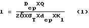
В отличие от прототипа в предлагаемом авторами НРС сопловой блок снабжен выступающим за срез сопла резьбовым кольцом с упорным буртом, воспламенитель выполнен с упирающимся в бурт кольца фланцем, перекрывающим выходное сечение сопла и контактирующим через обтюратор с торцем соплового блока, крышка установлена и зафиксирована на кольце, длина резьбового участка которого определяется из соотношения

где l - длина резьбового участка;
Dср - средний диаметр надрезьбового участка кольца;
Q - усилие форсирования;
δ - толщина резьбового участка;
σT - предел текучести материала кольца;
dср - средний диаметр резьбы кольца;
К1 = (14,5 - 15,5) - экспериментально установленный коэффициент;
при этом съемный токопроводящий элемент выполнен в виде изолированной от корпуса снаряда консольно закрепленной пружины, выступающей за калибр снаряда.In contrast to the prototype, the nozzle block proposed by the authors of the LDCs is equipped with a threaded ring with a thrust shoulder protruding beyond the nozzle edge, the igniter is made with a flange that abuts the shoulder of the ring, overlapping the nozzle exit section and contacting through the obturator with the nozzle block end face, the lid is mounted and fixed on the ring, the length of the threaded section which is determined from the ratio
where l is the length of the threaded section;
D cf - the average diameter of the notched portion of the ring;
Q is the force of forcing;
δ is the thickness of the threaded section;
σ T is the yield strength of the ring material;
d cf - the average diameter of the thread of the ring;
K 1 = (14.5 - 15.5) - experimentally established coefficient;
in this case, the removable conductive element is made in the form of a cantilever fixed spring isolated from the shell of the projection, protruding beyond the caliber of the projectile.
Указанные признаки, отличительные от прототипа и на которые распространяется испрашиваемый объем правовой защиты, во всех случаях достаточны. These signs, distinctive from the prototype and to which the requested amount of legal protection applies, are sufficient in all cases.
Задачей предлагаемого изобретения является повышение дальности и кучности стрельбы, обеспечение безотказной работы, а также увеличение уровня безопасности реактивного снаряда и возможности стрельбы из пусковых установок с различными схемами цепей запуска. The objective of the invention is to increase the range and accuracy of firing, ensuring trouble-free operation, as well as increasing the level of safety of a rocket and the possibility of firing from launchers with various schemes of launch circuits.
Новая совокупность конструктивных элементов, а также наличие связей между деталями заявляемого НРС позволяет:
- за счет размещения на сопловом блоке резьбового кольца с упорным буртом в сочетании с выполнением корпуса воспламенителя с упертым в бурт кольца фланцем, перекрывающим выходное сечение соплового блока:
а) повысить стабильность выхода двигателя на режим и уменьшить начальные возмущения, действующие на реактивный снаряд, а также создать узел форсирования двигателя, не связанный с конструкцией и механическими характеристиками материала крышки, и использовать для этого узла материалы со стабильными механическими характеристиками;
б) улучшить внутрибаллистические характеристики двигателя, обеспечив срыв кольца вместе с воспламенителем и крышкой при выходе двигателя на режим, уменьшить донное сопротивление, а также увеличить диаметр выходного сечения соплового блока и тем самым повысить дальность стрельбы НРС;
- уменьшить вероятность невоспламенения заряда двигателя и потери им герметичности при служебном обращении, т.е. повысить уровень безотказной работы НРС за счет контакта фланца воспламенителя через обтюратор с торцем выходного сечения соплового блока;
- за счет установки и фиксации крышки на выступающей части кольца исключить ее влияние на процесс срыва кольца, а также обеспечить установку крышки в любое требуемое угловое положение и закрепление ее в этом положении, чем обеспечивается возможность использования НРС для запуска из различных ПУ;
- определение длины резьбового участка кольца из соотношения

где l - длина резьбового участка;
Dср - средний диаметр надрезьбового участка кольца;
Q - усилие форсирования;
δ - толщина резьбового участка;
σT - предел текучести материала кольца;
dср - средний диаметр резьбы кольца;
К1 = (14,5 - 15,5) - экспериментально установленный коэффициент
позволяет обеспечить заданное усилие форсирования с учетом конструктивных и технологических особенностей предлагаемого устройства, а также исключить разрушение кольца вне резьбового участка;
- за счет выполнения съемного токопроводящего элемента в виде изолированной от корпуса снаряда консольно закрепленной пружины, выступающей за калибр снаряда, обеспечить изоляцию второго контакта от корпуса снаряда при стрельбе из пусковой установки, оснащенной однопроводной схемой запуска, что предотвращает передачу зарядов статического электричества и токов наводки, накапливаемых на корпусе НРС, на воспламенитель и исключает несанкционированный запуск двигателя, кроме того, обеспечить надежную электрическую связь второго контакта с внутренней поверхностью направляющей и, следовательно, с корпусом пусковой установки, что также повышает безопасность реактивного снаряда при служебном обращении в процессе эксплуатации;
Сущность изобретения заключается в том, что в неуправляемом реактивном снаряде, содержащем взрыватель, боевую часть, ракетный двигатель, ведущий штифт, воспламенитель, сопловой блок, крышку с контактным сектором и вторым контактом со съемным токопроводящим элементом, сопловой блок снабжен выступающим за срез сопла резьбовым кольцом с упорным буртом, воспламенитель выполнен с упирающимся в бурт кольца фланцем, перекрывающим выходное сечение сопла и контактирующим через обтюратор с торцем соплового блока, крышка установлена и зафиксирована на кольце, длина резьбового участка которого определяется из соотношения
где l - длина резьбового участка;
Dср - средний диаметр надрезьбового участка кольца;
Q - усилие форсирования;
δ - толщина резьбового участка;
σT - предел текучести материала кольца;
dср - средний диаметр резьбы кольца;
К1 = (14,5 - 15,5) - экспериментально установленный коэффициент
при этом съемный токопроводящий элемент выполнен в виде изолированной от корпуса снаряда консольно закрепленной пружины, выступающей за калибр снаряда.A new set of structural elements, as well as the presence of links between the details of the proposed LDCs, allows:
- due to the placement of a threaded ring with a thrust collar on the nozzle block in combination with an igniter body with a flange resting on the collar of the ring, overlapping the outlet section of the nozzle block:
a) increase the stability of the engine’s output to the regime and reduce the initial disturbances acting on the rocket, as well as create an engine boost assembly that is not related to the design and mechanical characteristics of the cover material, and use materials with stable mechanical characteristics for this assembly;
b) to improve the internal ballistic characteristics of the engine, ensuring that the ring with the igniter and cover break when the engine enters the mode, reduce the bottom resistance, and also increase the diameter of the output section of the nozzle block and thereby increase the firing range of the LDCs;
- reduce the likelihood of non-ignition of the engine charge and loss of tightness during official handling, i.e. to increase the LDC uptime due to the contact of the ignitor flange through the obturator with the end face of the nozzle block output section;
- due to the installation and fixation of the cover on the protruding part of the ring to exclude its influence on the process of disruption of the ring, as well as to ensure that the cover is installed in any desired angular position and secured in this position, which makes it possible to use LDCs to launch from various launchers;
- determination of the length of the threaded section of the ring from the ratio
where l is the length of the threaded section;
D cf - the average diameter of the notched portion of the ring;
Q is the force of forcing;
δ is the thickness of the threaded section;
σ T is the yield strength of the ring material;
d cf - the average diameter of the thread of the ring;
K 1 = (14.5 - 15.5) - experimentally established coefficient
allows you to provide a given force forcing, taking into account the structural and technological features of the proposed device, and also to eliminate the destruction of the ring outside the threaded section;
- due to the implementation of a removable conductive element in the form of a cantilever fixed spring protruding from the projectile caliber, to ensure isolation of the second contact from the projectile body when firing from a launcher equipped with a single-wire trigger circuit, which prevents the transmission of static electricity charges and induction currents, accumulated on the housing of the LDCs on the igniter and eliminates unauthorized starting of the engine, in addition, to ensure reliable electrical connection of the second contact with the inner surface of the guide and, therefore, with the launcher body, which also increases the safety of a missile during official handling during operation;
The essence of the invention lies in the fact that in an uncontrolled missile containing a fuse, warhead, rocket engine, pin, igniter, nozzle block, a cover with a contact sector and a second contact with a removable conductive element, the nozzle block is provided with a threaded ring protruding beyond the nozzle exit with a persistent collar, the igniter is made with a flange abutting against the collar of the ring, overlapping the outlet section of the nozzle and contacting through the obturator with the end of the nozzle block, the cover is installed and fixed ana on the ring, the length of the threaded portion is determined by the relation
where l is the length of the threaded section;
D cf - the average diameter of the notched portion of the ring;
Q is the force of forcing;
δ is the thickness of the threaded section;
σ T is the yield strength of the ring material;
d cf - the average diameter of the thread of the ring;
K 1 = (14.5 - 15.5) - experimentally established coefficient
in this case, the removable conductive element is made in the form of a cantilever fixed spring isolated from the shell of the projection, protruding beyond the caliber of the projectile.
Сущность изобретения поясняется чертежами, где на фиг. 1 изображен общий вид НРС, на фиг. 2 - укрупненный вид хвостовой части соплового блока, на фиг. 3 - вид НРС со стороны крышки, на фиг. 4 - схема размещения НРС в направляющей ПУ, а на фиг. 5 - вид сзади на НРС, находящийся в направляющей ПУ. The invention is illustrated by drawings, where in FIG. 1 shows a general view of the LDCs; FIG. 2 is an enlarged view of the tail of the nozzle block; FIG. 3 is a view of the LDCs from the side of the lid; in FIG. 4 is a diagram of an arrangement of LDCs in a guide PU, and in FIG. 5 is a rear view of the LDCs located in the PU guide.
НРС (фиг. 1) содержит головной взрыватель 1, боевую часть 2, ракетный двигатель 3, ведущий штифт 4, воспламенитель 5, сопловой блок 6 и крышку 7 с контактным сектором 8 и вторым контактом 9. The LDC (Fig. 1) contains a head fuse 1, a warhead 2, a rocket engine 3, a driving pin 4, an igniter 5, a nozzle block 6, and a cover 7 with a contact sector 8 and a second contact 9.
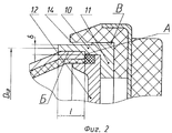
На выходном участке соплового блока 6 установлено резьбовое кольцо 10 (фиг. 2), выступающее за его срез А. На внутренней поверхности Б кольца 10 выполнен упорный бурт 11, в который упирается фланец 12 корпуса 13 воспламенителя 5. At the output section of the nozzle block 6, a threaded
Фланец 12 перекрывает выходное сечение соплового блока 6 и через обтюратор 14 контактирует с торцем выходного сечения соплового блока 6. The
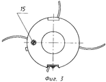
Крышка 7 установлена на выступающей части В кольца 10 и зафиксирована от проворота, например винтом 15 (фиг. 3). The cover 7 is mounted on the protruding part B of the
Съемный токопроводящий элемент 16 изолирован от корпуса НРС прокладкой 17 и установлен на втором контакте 9 контактной крышки 7 и закреплен на ней с помощью винта 18. The removable conductive element 16 is isolated from the housing of the LDC by the gasket 17 and mounted on the second contact 9 of the contact cover 7 and mounted on it with a screw 18.
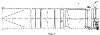
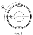
С помощью проводников 19 и 20 и винтов 21 и 22 воспламенитель 5 подключен к контактному сектору 8 и второму контакту 9. Линейное L (фиг. 4) и угловое (угол α) (фиг. 5) расположение контактного сектора 8 связано с расположением ведущего штифта 4. Using the conductors 19 and 20 and the screws 21 and 22, the igniter 5 is connected to the contact sector 8 and the second contact 9. The linear L (Fig. 4) and angular (angle α) (Fig. 5) location of the contact sector 8 is associated with the location of the pin 4.
При сборке снаряда крышка 7 выставляется на требуемую длину L и разворачивается на необходимый угол (α), после чего фиксируется в выбранном положении с помощью винта 15. When assembling the projectile, the lid 7 is set to the required length L and rotated to the required angle (α), after which it is fixed in the selected position using the
Если снаряд предназначен для стрельбы из ПУ с двухпроводной схемой запуска, то съемный токопроводящий элемент 16 не устанавливается. If the projectile is designed for firing from PU with a two-wire trigger circuit, then a removable conductive element 16 is not installed.
НРС функционирует следующим образом. LDCs operates as follows.
При заряжании снаряда в направляющую (рассматривается однопроводная схема запуска) съемный токопроводящий элемент 16 за счет своей упругости поджимается к внутренней поверхности Г направляющей, осуществляя подключение одного из проводников непосредственно к "массе" ПУ. When loading a projectile into the guide (a single-wire starting circuit is considered), the removable conductive element 16 is compressed due to its elasticity to the inner surface Г of the guide, connecting one of the conductors directly to the "mass" of the PU.
Одновременно ведущий штифт 4 попадает в замок направляющей и фиксируется в нем, при этом происходит автоматическая стыковка контактного сектора 8 и ответного контакта 23 на ПУ. At the same time, the leading pin 4 enters the lock of the guide and is fixed in it, while the automatic docking of the contact sector 8 and the
При подаче электрического импульса на контакт ПУ он передается на контактный сектор 8 и "массу" ПУ и через съемный токопроводящий элемент 16 и второй контакт 9 на проводники 19 и 20, подключенные к воспламенителю 5. Последний срабатывает и воспламеняет заряд ракетного двигателя 3. When an electric pulse is applied to the contact of the PU, it is transmitted to the contact sector 8 and the ground of the PU and through a removable conductive element 16 and the second contact 9 to the conductors 19 and 20 connected to the ignitor 5. The latter is triggered and ignites the charge of the rocket engine 3.
При достижении в двигателе 3 давления, равного давлению форсирования, передаваемого на упорный бурт 11 фланцем 12, кольцо 10 сбрасывается вместе с крышкой 7 путем раскрытия резьбового участка кольца 10, имеющего средний диаметр Dср, толщину δ и длину l. Снаряд начинает движение по направляющей, а затем полет по траектории.When the engine 3 reaches a pressure equal to the forcing pressure transmitted to the
При двухпроводной схеме запуска съемный токопроводящий элемент 16 не устанавливается и второй контакт 9 используется по прямому назначению. With a two-wire starting circuit, a removable conductive element 16 is not installed and the second contact 9 is used for its intended purpose.
Функционирование снаряда аналогично рассмотренному выше. The operation of the projectile is similar to that described above.
Выполнение реактивного снаряда в соответствии с изобретением повышает безотказность работы, уровень безопасности, обеспечивает возможность стрельбы из пусковых установок с различными схемами цепей запуска, а также позволяет повысить дальность стрельбы на 5-7%. Изобретение может быть использовано при разработке различных боеприпасов, в том числе боеприпасов реактивных систем залпового огня. The implementation of a missile in accordance with the invention increases the uptime, the level of security, provides the possibility of firing from launchers with various schemes of launch circuits, and also allows to increase the firing range by 5-7%. The invention can be used in the development of various ammunition, including ammunition of multiple launch rocket systems.
Указанный положительный эффект подтвержден испытаниям опытных образцов, выполненных в соответствии с изобретением. The specified positive effect is confirmed by testing prototypes made in accordance with the invention.
С использованием предлагаемого изобретения разработана конструкторская документация, изготовлена партия снарядов и проведены государственные испытания, намечено их серийное производство. Using the proposed invention, design documentation was developed, a batch of shells was made, and state tests were carried out, and mass production was planned.
Claims (1)
где l - длина резьбового участка;
Dср - средний диаметр надрезьбового участка кольца;
Q - усилие форсирования;
δ - толщина резьбового участка;
σT - предел текучести материала кольца;
dср - средний диаметр резьбы кольца;
К1=(14,5-15,5) - экспериментально установленный коэффициент,
при этом съемный токопроводящий элемент выполнен в виде изолированной от корпуса снаряда консольно закрепленной пружины, выступающей за калибр снаряда.An uncontrolled missile containing a fuse, warhead, rocket engine, pin, igniter, nozzle block, a cover with a contact sector and a second contact with a removable conductive element, characterized in that the nozzle block is provided with a threaded ring protruding beyond the nozzle section with a thrust ring collar, the igniter is made with a flange resting on the collar of the ring, overlapping the outlet section of the nozzle and in contact with the nozzle block end face, the cover is mounted and fixed on the ring, length the threaded portion is determined by the relation
where l is the length of the threaded section;
D cf - the average diameter of the notched portion of the ring;
Q is the force of forcing;
δ is the thickness of the threaded section;
σ T is the yield strength of the ring material;
d cf - the average diameter of the thread of the ring;
K 1 = (14.5-15.5) - experimentally established coefficient,
in this case, the removable conductive element is made in the form of a cantilever fixed spring isolated from the shell of the projection, protruding beyond the caliber of the projectile.
Priority Applications (1)
| Application Number | Priority Date | Filing Date | Title |
|---|---|---|---|
| RU2000115701A RU2176373C1 (en) | 2000-06-15 | 2000-06-15 | Rocket projectile |
Applications Claiming Priority (1)
| Application Number | Priority Date | Filing Date | Title |
|---|---|---|---|
| RU2000115701A RU2176373C1 (en) | 2000-06-15 | 2000-06-15 | Rocket projectile |
Publications (1)
| Publication Number | Publication Date |
|---|---|
| RU2176373C1 true RU2176373C1 (en) | 2001-11-27 |
Family
ID=20236364
Family Applications (1)
| Application Number | Title | Priority Date | Filing Date |
|---|---|---|---|
| RU2000115701A RU2176373C1 (en) | 2000-06-15 | 2000-06-15 | Rocket projectile |
Country Status (1)
| Country | Link |
|---|---|
| RU (1) | RU2176373C1 (en) |
Cited By (3)
| Publication number | Priority date | Publication date | Assignee | Title |
|---|---|---|---|---|
| RU2258890C1 (en) * | 2004-08-13 | 2005-08-20 | Федеральное Государственное унитарное предприятие "Государственное научно-производственное предприятие "Сплав" | Rocket projectile |
| RU2559657C1 (en) * | 2014-10-01 | 2015-08-10 | Открытое акционерное общество "Научно-производственное объединение "СПЛАВ" | Jet projectile rocket section |
| RU2798116C1 (en) * | 2022-11-29 | 2023-06-15 | Акционерное общество "Научно-производственное объединение "СПЛАВ" им. А.Н. Ганичева" | Missile part of a rotating rocket projectile launched from a smoothbore tubular guide |
Citations (4)
| Publication number | Priority date | Publication date | Assignee | Title |
|---|---|---|---|---|
| US3698321A (en) * | 1969-10-29 | 1972-10-17 | Thiokol Chemical Corp | Rocket assisted projectile |
| GB1507865A (en) * | 1975-10-22 | 1978-04-19 | Liljegren T | Projectiles |
| FR2570485B1 (en) * | 1984-09-19 | 1987-09-11 | France Etat Armement | ARTILLERY PROJECT WITH INCREASED RANGE |
| RU2107251C1 (en) * | 1996-08-12 | 1998-03-20 | Государственное научно-производственное предприятие "Сплав" | Rocket projectile launched from launching tube |
-
2000
- 2000-06-15 RU RU2000115701A patent/RU2176373C1/en active
Patent Citations (4)
| Publication number | Priority date | Publication date | Assignee | Title |
|---|---|---|---|---|
| US3698321A (en) * | 1969-10-29 | 1972-10-17 | Thiokol Chemical Corp | Rocket assisted projectile |
| GB1507865A (en) * | 1975-10-22 | 1978-04-19 | Liljegren T | Projectiles |
| FR2570485B1 (en) * | 1984-09-19 | 1987-09-11 | France Etat Armement | ARTILLERY PROJECT WITH INCREASED RANGE |
| RU2107251C1 (en) * | 1996-08-12 | 1998-03-20 | Государственное научно-производственное предприятие "Сплав" | Rocket projectile launched from launching tube |
Cited By (4)
| Publication number | Priority date | Publication date | Assignee | Title |
|---|---|---|---|---|
| RU2258890C1 (en) * | 2004-08-13 | 2005-08-20 | Федеральное Государственное унитарное предприятие "Государственное научно-производственное предприятие "Сплав" | Rocket projectile |
| RU2559657C1 (en) * | 2014-10-01 | 2015-08-10 | Открытое акционерное общество "Научно-производственное объединение "СПЛАВ" | Jet projectile rocket section |
| RU2798116C1 (en) * | 2022-11-29 | 2023-06-15 | Акционерное общество "Научно-производственное объединение "СПЛАВ" им. А.Н. Ганичева" | Missile part of a rotating rocket projectile launched from a smoothbore tubular guide |
| RU2829780C1 (en) * | 2023-05-25 | 2024-11-05 | Российская Федерация, от имени которой выступает Министерство обороны Российской Федерации | Unguided missile |
Similar Documents
| Publication | Publication Date | Title |
|---|---|---|
| US8132510B2 (en) | Remote setting for electronic systems in a projectile for chambered ammunition | |
| US4421030A (en) | In-line fuze concept for antiarmor tactical warheads | |
| US8230790B2 (en) | Remote setting for electronic systems in a projectile for chambered ammunition | |
| US4573411A (en) | Safety device for a weapon detonator or fuse | |
| RU2107251C1 (en) | Rocket projectile launched from launching tube | |
| US5147975A (en) | Remotely settable, multi-output, electronic time fuze and method of operation | |
| RU2176373C1 (en) | Rocket projectile | |
| US4278026A (en) | Rocket motor igniter, arming firing device | |
| RU2066441C1 (en) | Ballistic cap of guided artillery missile | |
| RU2089837C1 (en) | Ballistic cap of artillery guided missile | |
| EP0084095B1 (en) | Ballistic propulsion system for rifle grenades and similar projectiles | |
| RU2361171C1 (en) | Onboard thermal trap | |
| US3435767A (en) | Safety device for a projectile | |
| RU2241205C1 (en) | Time-contact fuse for naval salvo-fire systems | |
| EP3830514B1 (en) | Rocket armament launchable from a tubular launcher with an outside launcher non-ignition securing and motor separation during flight | |
| RU2812817C1 (en) | Barrel launching device, projectile and method of placement of projectile in device | |
| US4471696A (en) | High explosive projectile fuzing | |
| KR101937729B1 (en) | Firing test device and method for missile cable | |
| US3788227A (en) | Jet ignition device for a pyrotechnic fuze | |
| RU2092779C1 (en) | Tracer shell and device for switching of tracer on trajectory | |
| RU2226666C2 (en) | Cassette for remote mine planting | |
| RU2817052C1 (en) | Single-shot cartridge for remote mining | |
| CN117073468B (en) | Large-caliber machine gun fixed-distance air-explosion bomb for intercepting micro unmanned aerial vehicle | |
| RU2182304C1 (en) | Rocket electric contact device | |
| US3731629A (en) | Temperature discriminating dual igniter rocket ignition system |