RU2169373C2 - Device controlling range and velocity of travel of objects - Google Patents
Device controlling range and velocity of travel of objects Download PDFInfo
- Publication number
- RU2169373C2 RU2169373C2 RU99101261/28A RU99101261A RU2169373C2 RU 2169373 C2 RU2169373 C2 RU 2169373C2 RU 99101261/28 A RU99101261/28 A RU 99101261/28A RU 99101261 A RU99101261 A RU 99101261A RU 2169373 C2 RU2169373 C2 RU 2169373C2
- Authority
- RU
- Russia
- Prior art keywords
- lens
- range
- inputs
- outputs
- output
- Prior art date
Links
- 230000003287 optical effect Effects 0.000 claims abstract description 21
- 238000012545 processing Methods 0.000 claims abstract description 13
- 210000001747 pupil Anatomy 0.000 claims abstract description 9
- 230000033001 locomotion Effects 0.000 claims description 8
- 238000000605 extraction Methods 0.000 claims description 7
- 238000000926 separation method Methods 0.000 abstract description 2
- 230000000694 effects Effects 0.000 abstract 1
- 239000000126 substance Substances 0.000 abstract 1
- 238000005286 illumination Methods 0.000 description 8
- 230000005855 radiation Effects 0.000 description 8
- 238000010586 diagram Methods 0.000 description 4
- 238000013461 design Methods 0.000 description 3
- 239000004065 semiconductor Substances 0.000 description 3
- 238000013459 approach Methods 0.000 description 2
- 230000005693 optoelectronics Effects 0.000 description 2
- 238000006073 displacement reaction Methods 0.000 description 1
- 230000036039 immunity Effects 0.000 description 1
- 238000000034 method Methods 0.000 description 1
- 230000005236 sound signal Effects 0.000 description 1
- 238000012360 testing method Methods 0.000 description 1
- 238000000411 transmission spectrum Methods 0.000 description 1
- 230000001960 triggered effect Effects 0.000 description 1
Images
Landscapes
- Optical Radar Systems And Details Thereof (AREA)
Abstract
Description
Изобретение относится к области навигации, в частности и к оптико-электронным устройствам контроля скорости движения объектов, и может быть использовано для предотвращения столкновения транспортных средств. The invention relates to the field of navigation, in particular, to optical-electronic devices for controlling the speed of objects, and can be used to prevent collision of vehicles.
Известно устройство для определения скорости движения объектов, содержащее два разнесенных оптико-электронных приемника и подключенные к выходам оптико-электронных приемников в каждом канале, последовательно соединенные схему сравнения амплитуд, триггер, схему совпадений и индикатор, подключенный к выходу схем сравнения амплитуд. Формирователь импульсов, выход которого подключен к другому входу схемы совпадений каждого канала, выход схемы сравнения амплитуд каждого канала дополнительно подключен к второму входу триггера другого канала (1). A device for determining the speed of movement of objects is known, comprising two spaced apart optoelectronic receivers and connected to the outputs of optoelectronic receivers in each channel, serially connected amplitude comparison circuit, trigger, coincidence circuit, and an indicator connected to the output of amplitude comparison circuits. A pulse shaper whose output is connected to another input of the coincidence circuit of each channel, the output of the amplitude comparison circuit of each channel is additionally connected to the second trigger input of the other channel (1).
К причинам, препятствующим достижению указанного ниже технического результата при использовании известного устройства, относится то, что в известном устройстве невозможно определить дальность до объекта. The reasons that impede the achievement of the technical result indicated below when using the known device include the fact that it is impossible to determine the distance to the object in the known device.
Известно также устройство для измерения дальности до точечной цели (2), которое основано на принципе расфокусировки изображения. A device for measuring the distance to a point target (2) is also known, which is based on the principle of defocusing an image.
Известное устройство (2) содержит объектив, непрозрачный диск, расположенный за объективом и имеющий узкую радиальную щель и вращающийся с постоянной скоростью, два фотоприемника, расположенные за диском, выходы которых подключены ко входам дискриминатора, а также измеритель, подключенный к выходу дискриминатора. Если цель находится на таком расстоянии, что фокусируется в плоскость размещения вращающегося диска, то два фотоприемника выдадут сигналы, совпадающие во времени в момент прохождения щели через изображения цели. The known device (2) contains a lens, an opaque disk located behind the lens and having a narrow radial slot and rotating at a constant speed, two photodetectors located behind the disk, the outputs of which are connected to the inputs of the discriminator, as well as a meter connected to the output of the discriminator. If the target is at such a distance that it focuses in the plane of placement of the rotating disk, then two photodetectors will give out signals that coincide in time at the moment the gap passes through the target image.
Если же расстояние до цели изменится так, что плоскость изображения переместится в сторону от плоскости расположения вращающегося диска, то, во-первых, форма импульсов изменится (импульс несколько расплывается), а во-вторых, они появятся на выходах фотодетекторов не одновременно, а с некоторым сдвигом во времени. Причем величина этого сдвига зависит от степени ухода плоскости изображения, т.е. от дальности до цели. Уход плоскости изображения в противоположную сторону поменяет порядок появления импульсов на выходах фотодетектора. If the distance to the target changes so that the image plane moves away from the plane of the location of the rotating disk, then, firstly, the shape of the pulses will change (the pulse diffuses somewhat), and secondly, they will appear at the outputs of the photo detectors not simultaneously, but with some time shift. Moreover, the magnitude of this shift depends on the degree of departure of the image plane, i.e. from range to target. Departure of the image plane in the opposite direction will change the order of appearance of pulses at the outputs of the photodetector.
Последующие элементы схемы измеряют временный интервал между импульсами с выходом фотодетекторов и определяют дальность цели. Для этого используется фазовый дискриминатор и измеритель. Subsequent circuit elements measure the time interval between pulses with the output of photodetectors and determine the range of the target. For this, a phase discriminator and a meter are used.
К причинам, препятствующим достижению указанного ниже технического результата, относится то, что известное устройство не позволяет определить скорость движения объекта, а также сложность конструкции, связанная с наличием электромеханических вращающихся узлов. For reasons that impede the achievement of the technical result indicated below, the known device does not allow to determine the speed of the object, as well as the complexity of the design associated with the presence of electromechanical rotating units.
Известен также фотоэлектрический датчик скорости вращения, который по конструктивным признакам может быть указан в качестве прототипа предложенного технического решения (3). A photoelectric rotational speed sensor is also known, which by design features can be indicated as a prototype of the proposed technical solution (3).
Известное устройство (3) содержит последовательно расположенные оптически согласованные осветитель, объектив, линзу, позиционно-чувствительный четырехплощадочный фотоприемник, квадранты которого соединены с входами четырех предварительных усилителей. Выходы первого и второго предварительных усилителей соединены с входами суммирующего усилителя. Кроме того, известное устройство содержит разностный усилитель, два компаратора и элемент И. При этом выходы третьего и четвертого предварительных усилителей соединены с входами разностного усилителя, а выходы суммирующего и разностного усилителей через компараторы соединены соответственно с первым и вторым входами элемента И. The known device (3) contains sequentially located optically matched illuminator, lens, lens, position-sensitive four-site photodetector, the quadrants of which are connected to the inputs of four pre-amplifiers. The outputs of the first and second pre-amplifiers are connected to the inputs of the summing amplifier. In addition, the known device contains a difference amplifier, two comparators and an element I. Moreover, the outputs of the third and fourth pre-amplifiers are connected to the inputs of the difference amplifier, and the outputs of the summing and difference amplifiers through the comparators are connected respectively to the first and second inputs of the element I.
К причинам, препятствующим достижению технического результата, указанного ниже, относятся ограниченные функциональные возможности устройства, связанные с тем, что оно не позволяет определить дальность и радиальную скорость движения объекта. The reasons that impede the achievement of the technical result indicated below include the limited functionality of the device due to the fact that it does not allow to determine the range and radial speed of the object.
Задача заявляемого изобретения - создание устройства с расширенными функциональными возможностями, заключающимися в определении двух фиксированных дистанций нахождения объекта Z1 и Z2 и радиальной скорости его приближения.The task of the invention is the creation of a device with enhanced functionality, which consists in determining two fixed distances for finding the object Z 1 and Z 2 and the radial velocity of its approximation.
Технический результат - расширение функциональных возможностей устройства. The technical result is the expansion of the functionality of the device.
Сущность предложенного технического решения заключается в том, что в устройство для контроля скорости движения объектов, содержащее источники модулированного света (лазер) и оптически сопряженные с ним зеркало, объектив и позиционно-чувствительный четырехплощадочный фотоприемник, выходы квадрантов которого подключены ко входам блока обработки сигналов, введены непрозрачная маска оптический элемент формы квадранта. При этом непрозрачная маска установлена так, чтобы перекрывала часть входного зрачка объектива, а границы раздела квадрантов четырехплощадочного фотоприемника проходят параллельно или перпендикулярно краям непрозрачной маски и оптического элемента. The essence of the proposed technical solution lies in the fact that the device for controlling the speed of movement of objects containing sources of modulated light (laser) and a mirror optically coupled to it, a lens and a position-sensitive four-area photodetector, the quadrant outputs of which are connected to the inputs of the signal processing unit, are introduced opaque mask is an optical element of a quadrant shape. In this case, the opaque mask is set so that it overlaps part of the entrance pupil of the lens, and the interface between the quadrants of the four-site photodetector runs parallel or perpendicular to the edges of the opaque mask and the optical element.
Кроме того, блок обработки сигналов содержит первый и второй усилители, выходы которых подключены у первому и второму выходам блока выделения сигналов дальности, первый и второй выходы последнего являются первым и вторым информационными выходами устройства и одновременно подключены к соответствующим выходам триггера, первый вход которого запараллелен с выходом формирователя импульсов, а выходы последних подключены к входам схемы сравнения дальностей. In addition, the signal processing unit contains the first and second amplifiers, the outputs of which are connected at the first and second outputs of the range signal extraction unit, the first and second outputs of the latter are the first and second information outputs of the device and are simultaneously connected to the corresponding outputs of the trigger, the first input of which is parallel with the output of the pulse shaper, and the outputs of the latter are connected to the inputs of the range comparison circuit.
Блок выделения сигналов дальности при этом содержит первый и второй селективные усилители, выходы которых подключены к схеме деления, выход которого подключен к запараллельным первым входам первого и второго компараторов, вторые входы которых подключены соответственно к выходам первого и второго блоков задания констант. При этом выходы компараторов являются выходами блока. The range signal extraction unit contains first and second selective amplifiers, the outputs of which are connected to the division circuit, the output of which is connected to the parallel first inputs of the first and second comparators, the second inputs of which are connected respectively to the outputs of the first and second constant setting blocks. The outputs of the comparators are the outputs of the block.
Указанные конструктивные признаки являются существенными и позволяют достичь поставленную задачу и технический результат - расширить функциональные возможности устройства, заключающееся в определении дальности и радиальной скорости движения объекта. These design features are essential and allow you to achieve the task and technical result - to expand the functionality of the device, which consists in determining the range and radial velocity of the object.
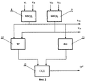
На фиг. 1а представлена блок схема устройства, где 1 - источник подсвета (лазер), 2 - зеркало, 3 - объектив, 4 - непрозрачная шторка (маска), 5 - оптический элемент - прямоугольный сектор сферической линзы, 6 - позиционно чувствительный четырехплощадочный фотоприемник, 7 - блок обработки сигналов (БОС), V1V2 ± ΔV - информационные выходы устройства.In FIG. 1a shows a block diagram of the device, where 1 is the light source (laser), 2 is the mirror, 3 is the lens, 4 is the opaque curtain (mask), 5 is the optical element is the rectangular sector of the spherical lens, 6 is the positionally sensitive four-area photodetector, 7 - signal processing unit (BOS), V 1 V 2 ± ΔV - information outputs of the device.
На фиг. 1б изображен вид спереди входного зрачка объектива 3, часть которого перекрыта непрозрачной маской 4, а сзади установлен дополнительный оптический элемент 5. In FIG. 1b shows a front view of the entrance pupil of the
На фиг. 1в изображены квадранты I, II, III, IV фоточувствительной поверхности позиционно-чувствительного четырехплощадочного фотоприемника 6. In FIG. 1c shows quadrants I, II, III, IV of the photosensitive surface of a position-sensitive four-
На фиг. 2 приведена структурная схема блока обработки 7, где 8 и 9 - первый и второй блоки выделения сигналов дальности (БВСД), выходы которых являются первым Z1 и вторым Z2 информационными выходами устройства и они же подключены к входам триггера 10, а выход первого БВСД1 8 - дополнительно к входу формирователя импульсов 11. Выходы триггера 10 и формирователя импульсов 11 подключены к входам схемы сравнения длительностей 12, выход которой является третьим информационным выходом устройства ±ΔV.In FIG. 2 is a structural diagram of the processing unit 7, where 8 and 9 are the first and second blocks of the selection of range signals (BVSD), the outputs of which are the first Z 1 and second Z 2 information outputs of the device and they are also connected to the inputs of the
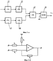
На фиг. 3а приведена структурная схема одного из возможных вариантов выполнения блока выделения сигнала дальности (8,9), где 13 и 14 - первый и второй селективные усилители, входы которых являются входами блока выделения сигнала дальности (8,9) (БВСД), а выходы подключены к входам соответствующих амплитудных детекторов 15,16, выходы которых подключены ко входам вычитающего усилителя 17, выход которого в свою очередь подключен к первому входу компаратора 18, на второй вход которого подается нулевой потенциал. Выход компаратора является выходом БВСД и одним из информационных выходов устройства Vz1 (или Vz2).In FIG. 3a shows a block diagram of one of the possible embodiments of the range signal extraction unit (8.9), where 13 and 14 are the first and second selective amplifiers whose inputs are inputs of the range signal extraction unit (8.9) (BVSD), and the outputs are connected to the inputs of the
На фиг. 3б приведена схема вычитающего усилителя 17, где A1 - операционный усилитель.In FIG. 3b is a diagram of a
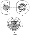
На фиг. 4 приводятся рисунки, поясняющие изменения диаметра и формы изображения подсвечиваемого кружка (пятна) в плоскости светочувствительного слоя позиционно-чувствительного четырехплощадочного фотоприемника 6 при использовании непрозрачной маски 4 при различных дальностях:
а) пятно находится в плоскости фокусировки объектива;
б) пятно перемещается от плоскости фокусировки в сторону объектива;
в) пятно перемещается от плоскости фокусировки в сторону удаления от объектива.In FIG. 4 are figures explaining changes in the diameter and shape of the image of the illuminated circle (spot) in the plane of the photosensitive layer of the position-sensitive four-
a) the spot is in the focus plane of the lens;
b) the spot moves from the focusing plane towards the lens;
c) the spot moves from the focus plane to the side away from the lens.
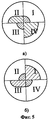
На фиг. 5 приводятся рисунки, поясняющие изменение изображения подсвечиваемого пятна в плоскости светочувствительного слоя фотоприемника 6 при различных дальностях:
а) пятно находится в плоскости фокусировки объектива 3;
б) пятно находится в плоскости фокусировки оптической системы, состоящей из части объектива 3 и дополнительного оптического элемента 5.In FIG. 5 are drawings explaining the change in the image of the highlighted spot in the plane of the photosensitive layer of the
a) the spot is in the focus plane of the
b) the spot is in the focusing plane of the optical system, consisting of a part of the
При использовании отличительных признаков описываемого устройства не выявлено каких-либо аналогичных известных решений. When using the distinguishing features of the described device is not revealed any similar known solutions.
Устройство для контроля скорости движения объектов функционирует следующим образом: излучение источника подсвета (лазера) 1 с помощью зеркала 2 направляется вдоль оптической оси объектива 3. В качестве источника подсвета может быть использован любой источник света, например светодиод. Для получения параллельного пучка света светодиод может быть установлен в фокусе линзы. С целью повышения отношения "сигнал-шум" перед объективом может быть установлен полосовой оптический фильтр, спектр пропускания которого совпадает с длиной излучения источника подсвета 1. Кроме того, излучение источника подсвета может быть модулировано по амплитуде на определенной фиксированной частоте. Для модуляции излучения полупроводникового лазера достаточно подать на излучатель электрические импульсы определенной частоты. В случае, когда в качестве источника подсвета используется светодиоды, полупроводниковый или твердотельный лазеры модуляция излучения достигается импульсным напряжением питания или накачки. A device for controlling the speed of movement of objects operates as follows: the radiation of the illumination source (laser) 1 is directed along the optical axis of the
Изображение пятна подсвечиваемого источником подсвета на поверхности контролируемого объекта фокусируется объективом 3 и оптическим элементом 5 в плоскость размещения светочувствительного слоя позиционно-чувствительного четырехплощадочного фотоприемника 6. The image of the spot illuminated by the illumination source on the surface of the controlled object is focused by the
Используемый позиционно-чувствительный четырехплощадочный фотоприемник является неразвертывающим. Этот приемник не требует накопления заряда. Со всех выходов четырех квадрантов независимо друг от друга в любой момент времени возможно снять информацию V1, V2, V3, V4, что позволяет модулировать по частоте подсвечивающий луч и осуществить частотную селекцию сигналов изображения, улучшить отношение сигнал/шум и повысить помехоустойчивость устройства. Светочувствительная поверхность квадрантов позиционно- чувствительного четырехплощадочного фотоприемника 6 размещается перпендикулярно оптической оси объектива 3. Причем оптическая ось проходит через центр фотоприемника - через точку пересечения границ раздела четырех квадрантов светочувствительного слоя. При этом одна из границ раздела параллельна краю непрозрачной шторки 4. Если подсвечиваемое пятно находится в плоскости, на которую фокусирован объектив 3, изображение этого пятна будет представлять собой кружок, диаметр которого определяется следующим образом:
![]()
где F - фокусное расстояние объектива 3,
Zсф - расстояние, на которое фокусирован объектив,
dΛ - диаметр подсвечивающего луча.The position-sensitive four-site photodetector used is non-deployable. This receiver does not require charge storage. From all outputs of the four quadrants independently of each other at any time it is possible to take information V 1 , V 2 , V 3 , V 4 , which allows you to modulate the frequency of the illuminating beam and to perform frequency selection of image signals, improve the signal-to-noise ratio and increase noise immunity devices. The photosensitive surface of the quadrants of the position-sensitive four-
![]()
where F is the focal length of the
Z sf - the distance at which the lens is focused,
dΛ is the diameter of the illuminating beam.
При расфокусировке, вызванной смещением контролируемого объекта и соответственно подсвечиваемого пятна относительно плоскости фокусировки объектива 3, происходит увеличение пятна изображения светочувствительного слоя четырехплощадочного фотоприемника 6. When defocusing caused by the displacement of the controlled object and, accordingly, the highlighted spot relative to the focusing plane of the
Известно, что для точечного объекта и непрозрачной маски 4 в виде полукруга установленный перед объективом кружок расфокусировки представляет собой круг, разделенный линией, параллельной линии раздела прозрачной и непрозрачной половинок входного зрачка объектива 3, т.е. маски 4. Излучение, составляющее каждую из половинок изображения, проходит через соответствующие половинки входного зрачка объектива 3. Причем порядок следования этих половинок определяется в зависимости от того - ближе находится точечный объект относительно плоскости фокусировки, а диаметр кружка расфокусировки dр может быть определен по формуле (4):
![]()
где D - диаметр входного зрачка объектива,
F - фокусное расстояние объектива,
Z - расстояние от объектива до объекта,
Zсф - расстояние, на которое сфокусирован объектив.It is known that for a point object and an opaque mask 4 in the form of a semicircle, the defocusing circle installed in front of the lens is a circle divided by a line parallel to the dividing line of the transparent and opaque halves of the entrance pupil of the
![]()
where D is the diameter of the entrance pupil of the lens,
F is the focal length of the lens,
Z is the distance from the lens to the object,
Z sf - the distance at which the lens is focused.
Благодаря непрозрачной маске (шторке) 4, установленной перед объективом, для точечного объекта кружок расфокусировки представляет собой половину круга, граница которого параллельна краю непрозрачной маски (шторки) 4, а также параллельная границе раздела квадрантов светочувствительного слоя четырехплощадочного фотоприемника 6. Due to the opaque mask (curtain) 4 installed in front of the lens, for a point object, the defocusing circle is half the circle whose boundary is parallel to the edge of the opaque mask (curtain) 4, as well as parallel to the interface of the quadrants of the photosensitive layer of the four-
На фиг. 4 представлены возникающие при этом картинки. In FIG. 4 presents the resulting images.
Так, для сфокусированного подсвечиваемого пятна его изображение проектируется на фоточувствительную поверхность четырехплощадочного фотоприемника 6 симметрично относительно границы раздела верхней (В) (квадранты I, II) и нижней половинок. При этом напряжение, вырабатываемое верхней и нижней половинками фотоприемника, равны. Смещение подсвечиваемого пятна по дальности вызывает расфокусировку, причем получаемое при этом изображение становится несимметричным относительно границы раздела половинок В и H фотоприемника 6. So, for a focused illuminated spot, its image is projected onto the photosensitive surface of the four-
На фиг. 4б показано как формируется результирующее изображение подсвечиваемого пятна при его перемещении в сторону приближения от плоскости фокусировки. Приближение вызывает размытие изображения пятна в кружок расфокусировки диаметром dр *. При этом, так как размер изображения подсвечиваемого пятна, перекрывающий верхнюю половину (I и II квадранты) четырехплощадочного фотоприемника 6, больше, чем размер нижнего изображения, то напряжения V1 + V2, вырабатываемые верхними квадрантами I и II, также будут больше, чем нижними (III, IV) V3 + V4.In FIG. 4b shows how the resulting image of the highlighted spot is formed when it moves toward the approximate direction from the focus plane. The approximation causes blurring of the image of the spot in the defocus circle with a diameter d p * . Moreover, since the image size of the illuminated spot that covers the upper half (I and II quadrants) of the four-
При удалении подсвечиваемого пятна от плоскости фокусировки происходит рост диаметра кружка расфокусировки на величину dр **, результирующее изображение подсвечиваемого пятна примет вид, изображенный на фиг. 4в. При этом напряжение V3 + V4, вырабатываемое нижней половиной (квадрантами III, IV) четырехплощадочного фотоприемника 6, будет больше напряжения V1 + V2, вырабатываемого верхней половиной (квадрантами I, II).When the illuminated spot is removed from the focusing plane, the diameter of the defocusing circle increases by d p ** , the resulting image of the illuminated spot takes the form shown in FIG. 4c. In this case, the voltage V 3 + V 4 generated by the lower half (quadrants III, IV) of the four-
Если же оставшуюся открытой часть входного зрачка объектива перекрыть наполовину дополнительным оптическим элементом (одной четвертой частью сферической линзы), то изображение, получаемое на фоточувствительной поверхности приемника, будет таким, как показано на фиг. 5. На фиг. 5а показано изображение, получаемое в момент, когда подсвечиваемое пятно находится в плоскости, на которую сфокусирован объектив 3. На фиг. 5б показано изображение, полученное в момент нахождения пятна в плоскости, на которую сфокусирована оптическая система, состоящая из части входного зрачка объектива 3 и дополнительного оптического элемента 5. Из этих рисунков видно, что в первом случае площади частей пятна расфокусировки, попадающих на сектора I и III фотоприемника, а следовательно, и электрические сигналы, снимаемые с них VI и VIII равны между собой. Во втором случае равны площади частей пятна, попадающих на сектора II и IV, что соответствует равенству VII и VIV.If the remaining open part of the entrance pupil of the lens is half covered with an additional optical element (one fourth of the spherical lens), then the image obtained on the photosensitive surface of the receiver will be as shown in FIG. 5. In FIG. 5a shows the image obtained at the moment when the illuminated spot is in the plane onto which the
Обработка величин электрических сигналов VI, VII и VIII, VIV с целью извлечения информации о скорости движения объекта осуществляется в блоке обработки сигналов 7.The processing of the values of the electrical signals V I , V II and V III , V IV in order to extract information about the speed of the object is carried out in the signal processing unit 7.
Блок обработки сигналов дальности 7 (фиг. 2) функционирует следующим образом: напряжения VI и VIII с 1, 3 выходов квадрантов позиционно-чувствительного четырехплощадочного фотоприемника 6 поступают на входы первого блока выделения сигнала дальности БВСДI) 8, а напряжения VII и VIV с выходов 2, 4 квадрантов фотоприемника 6 - на входы второго БВСД2 9. Оба БВСД 8, 9 абсолютно одинаковы.The range signal processing unit 7 (Fig. 2) operates as follows: the voltages V I and V III from 1, 3 of the quadrant outputs of the position-sensitive four-
БВСД имеет на входе первый 13 и второй 14 селективные (резонансные) усилители, настроенные на частоту модуляции лазерного излучения (фиг. 3а). Усиленные сигналы детектируются амплитудными детекторами 15, 16 и поступают на входы вычитающего усилителя 17. Результат операции VI - VIII (или VIII - VIV) далее поступает на вход компаратора 18, где сравнивается с нулем, установленным на его втором входе. Если расстояние до подсвечиваемой точки объекта равно расстоянию Z1, на которое сфокусирован объектив устройства, сигнал на выходе схемы вычитания равен нулю. При расстоянии, большем сфокусированного, сигнал на выходе схемы вычитания меньше нуля, а при расстоянии до точки подсвета, меньшем сфокусированного, - больше нуля.The BVSD has at the input the first 13 and second 14 selective (resonant) amplifiers tuned to the modulation frequency of the laser radiation (Fig. 3a). The amplified signals are detected by the
Выбором объектива 3 и оптического элемента 5 определяется зона по дальности, Z1 и Z2, при попадании в которую приближающее подсвечиваемое пятно проявление сигнала сперва на выходе первого БВСД18, а при дальнейшем и на выходе второго БВСД29.The choice of the
Таким образом, БВСД 8 и ББСД 9 вырабатывают электрические сигналы Vz1 и Vz2 при прохождении объектов плоскостей, удаленных на расстоянии Z1 и Z2 от объектива, соответственно. Сигналы VI и VII последовательно поступают на соответствующие первый и второй входы триггера 10, который формирует импульс, дальность которого соответствует времени прохождения расстояния ΔZ = Z1-Z2. Формирователь импульсов 11, запускаемый сигналом Vz1, формирует импульс эталонной длительности, соответствующий допустимому значению скорости объекта.Thus,
![]()
Схема сравнения длительностей 12 сравнивает τ и τэ и на выходе формирует сигнал ± ΔV, величина и полярность которого характеризует отклонение скорости объекта от допустимой. ![]()
The
Выходные сигналы блоков выделения сигналов дальности Vz1 и Vz2 могут быть использованы как информационные для определения границ зон "предупреждения" и "опасного приближения" в системах предупреждения столкновения транспортных средств, захватов роботов-манипуляторов и т.д.The output signals of the signal separation blocks of the range signals V z1 and V z2 can be used as information for determining the boundaries of the “warning” and “dangerous approach” zones in systems for preventing collisions of vehicles, captures of robotic manipulators, etc.
Источник подсвета 1 может быть выполнен как на основе газового лазера, так и на базе полупроводникового лазера, например, типа ТН-10, снабженного фокусирующей оптической системой, создающей узкий пучок подсвета. Причем частота импульсов излучения должна соответствовать резонансной частоте настройки усилителей 13 и 14. В качестве позиционно-четырехплощадочного фотоприемника 6 может использоваться фотодиод ФДК-142. В качестве компараторов могут быть использованы микросхемы КР-597СА2. Схема вычитающего усилителя может быть собрана на операционном усилителе 5. Если цель двигается и находится на оптической оси объектива устройства, то оно может работать без источника подсвета. Illumination source 1 can be performed both on the basis of a gas laser and on the basis of a semiconductor laser, for example, of the ТН-10 type, equipped with a focusing optical system that creates a narrow illumination beam. Moreover, the frequency of the radiation pulses should correspond to the resonant tuning frequency of the
Используя в составе блока обработки сигналов 7 микроЭВМ со средствами ввода-выхода аналоговой информации, возможно произвести линеаризацию характеристики датчика и возложить на микроЭВМ все вычислительные операции. Using as part of the signal processing unit 7 microcomputers with analogue input-output means, it is possible to linearize the sensor characteristics and assign all the computing operations to the microcomputer.
При расположении и движении светящейся цели вдоль оси объектива устройства оно может работать и в пассивном режиме, т.е. без источника подсвета. Такие задачи возникают, когда светящаяся цель двигается вдоль одной прямой или датчик установлен на следящей платформе. В этом случае необходимость в признаках 1 и 2 отпадает, а усилители 13 и 14 в блоке обработки сигналов должны быть усилителями постоянного тока. With the location and movement of the luminous target along the axis of the lens of the device, it can also work in a passive mode, i.e. without light source. Such tasks arise when the luminous target moves along one straight line or the sensor is installed on a tracking platform. In this case, the need for signs 1 and 2 disappears, and the
По сравнению с прототипом предложенное техническое решение обладает более широкими функциональными возможностями. Оно позволяет определить дальность и скорость относительного движения объекта. Compared with the prototype, the proposed technical solution has wider functionality. It allows you to determine the range and speed of the relative motion of the object.
Выходные сигналы рассогласования Vz1Vz2 могут быть поданы для отработки на рулевые органы управления устройством. Объект, на котором установлен измеритель, удаляется или приближается, сводя сигнал рассогласования к нулю. Данное устройство может быть использовано в теплотехнике в качестве указателя препятствий слепым. При этом сигналы рассогласования Vz1Vz2 могут быть преобразованы в звуковой сигнал, тональность которого меняется в зависимости от величины и знака Vz1Vz2.The output mismatch signals V z1 V z2 can be fed to the steering controls of the device for testing. The object on which the meter is mounted moves away or approaches, reducing the error signal to zero. This device can be used in heat engineering as an indicator of obstacles to the blind. In this case, the mismatch signals V z1 V z2 can be converted into an audio signal, the tonality of which varies depending on the magnitude and sign of V z1 V z2 .
Устройство с высокой экономической эффективностью может быть применено в системах управления роботов-манипуляторов и в системах предупреждения столкновений транспортных средств и летательных аппаратов. Сигнал рассогласования также может быть использован для автоматической фокусировки объектива на объект. The device with high economic efficiency can be used in control systems of robotic manipulators and in collision avoidance systems of vehicles and aircraft. The error signal can also be used to automatically focus the lens on the subject.
Источники информации, принятые во внимание при составлении заявки
1. Устройство для определения скорости движения объектов. Заявка Великобритании N 1410553, G 01 P 3/68, 1975 г.Sources of information taken into account when preparing the application
1. Device for determining the speed of movement of objects. UK application N 1410553, G 01
2. Устройство для измерения дальности. Патент США N 3765765, НКИ 365-4. 2. A device for measuring range. U.S. Patent No. 3,765,765, NKI 365-4.
3. Воробьев С. А. , Баранов Ю.И., Типаев В.В. Фотоэлектрический датчик скорости вращения. SU N 1081543, G 01 P З/36 23.03.84. 3. Vorobyov S. A., Baranov Yu.I., Tipaev V.V. Photoelectric rotational speed sensor. SU N 1081543, G 01 P З / 36 03/23/84.
4. Украинский С.В. Стереоскопический базис однообъективной стереотелевизионной системы. "Техника кино и телевидения". N7, с.48, 1982 г. 4. Ukrainian S.V. Stereoscopic basis of a single-lens stereo television system. "Technique of film and television." N7, p. 48, 1982
5. Шилов В.Л. Линейные интегральные схемы. М.: Сов. Радио, 1979, с.158. 5. Shilov V.L. Line integrated circuits. M .: Sov. Radio 1979, p. 158.
Claims (3)
Priority Applications (1)
| Application Number | Priority Date | Filing Date | Title |
|---|---|---|---|
| RU99101261/28A RU2169373C2 (en) | 1999-01-18 | 1999-01-18 | Device controlling range and velocity of travel of objects |
Applications Claiming Priority (1)
| Application Number | Priority Date | Filing Date | Title |
|---|---|---|---|
| RU99101261/28A RU2169373C2 (en) | 1999-01-18 | 1999-01-18 | Device controlling range and velocity of travel of objects |
Publications (2)
| Publication Number | Publication Date |
|---|---|
| RU99101261A RU99101261A (en) | 2000-10-20 |
| RU2169373C2 true RU2169373C2 (en) | 2001-06-20 |
Family
ID=20214970
Family Applications (1)
| Application Number | Title | Priority Date | Filing Date |
|---|---|---|---|
| RU99101261/28A RU2169373C2 (en) | 1999-01-18 | 1999-01-18 | Device controlling range and velocity of travel of objects |
Country Status (1)
| Country | Link |
|---|---|
| RU (1) | RU2169373C2 (en) |
Cited By (5)
| Publication number | Priority date | Publication date | Assignee | Title |
|---|---|---|---|---|
| WO2004059327A1 (en) * | 2002-12-26 | 2004-07-15 | Limited Liability Company 'unique Ic's' | Integration circuit for an optical sensor for the displacement vector and velocity of an observed object |
| RU2378705C1 (en) * | 2008-06-03 | 2010-01-10 | Федеральное государственное унитарное предприятие "Научно-исследовательский институт "Полюс" им. М.Ф. Стельмаха" | Method of determining range and/or speed of remote object |
| RU2407032C1 (en) * | 2009-04-01 | 2010-12-20 | Общество с ограниченной ответственностью, научно-производственное предприятие "Автозрение" | Method to control transport facility speed at turns |
| RU2444761C1 (en) * | 2010-07-13 | 2012-03-10 | Федеральное государственное учреждение "Государственный научно-исследовательский испытательный институт проблем технической защиты информации Федеральной службы по техническому и экспортному контролю" | Coordinate-sensitive photodetector |
| RU2733804C1 (en) * | 2017-09-19 | 2020-10-07 | Сафран Электроникс Энд Дифенс | Target tracking device comprising photodetector with quadrants |
Citations (2)
| Publication number | Priority date | Publication date | Assignee | Title |
|---|---|---|---|---|
| FR2174863B1 (en) * | 1972-03-06 | 1975-08-22 | Leitz Ernst Gmbh | |
| DE2659204A1 (en) * | 1976-12-14 | 1978-06-29 | Martin Marietta Corp | METHOD AND DEVICE FOR SIGNAL PROCESSING |
-
1999
- 1999-01-18 RU RU99101261/28A patent/RU2169373C2/en not_active IP Right Cessation
Patent Citations (2)
| Publication number | Priority date | Publication date | Assignee | Title |
|---|---|---|---|---|
| FR2174863B1 (en) * | 1972-03-06 | 1975-08-22 | Leitz Ernst Gmbh | |
| DE2659204A1 (en) * | 1976-12-14 | 1978-06-29 | Martin Marietta Corp | METHOD AND DEVICE FOR SIGNAL PROCESSING |
Cited By (6)
| Publication number | Priority date | Publication date | Assignee | Title |
|---|---|---|---|---|
| WO2004059327A1 (en) * | 2002-12-26 | 2004-07-15 | Limited Liability Company 'unique Ic's' | Integration circuit for an optical sensor for the displacement vector and velocity of an observed object |
| RU2232997C1 (en) * | 2002-12-26 | 2004-07-20 | ООО "Юник Ай Сиз" | Integrated circuit of optical sensor of movement and speed vector of observed object |
| RU2378705C1 (en) * | 2008-06-03 | 2010-01-10 | Федеральное государственное унитарное предприятие "Научно-исследовательский институт "Полюс" им. М.Ф. Стельмаха" | Method of determining range and/or speed of remote object |
| RU2407032C1 (en) * | 2009-04-01 | 2010-12-20 | Общество с ограниченной ответственностью, научно-производственное предприятие "Автозрение" | Method to control transport facility speed at turns |
| RU2444761C1 (en) * | 2010-07-13 | 2012-03-10 | Федеральное государственное учреждение "Государственный научно-исследовательский испытательный институт проблем технической защиты информации Федеральной службы по техническому и экспортному контролю" | Coordinate-sensitive photodetector |
| RU2733804C1 (en) * | 2017-09-19 | 2020-10-07 | Сафран Электроникс Энд Дифенс | Target tracking device comprising photodetector with quadrants |
Similar Documents
| Publication | Publication Date | Title |
|---|---|---|
| US11859976B2 (en) | Automatic locating of target marks | |
| US10281262B2 (en) | Range-finder apparatus, methods, and applications | |
| CN105445748B (en) | Electro-optical distance measurement device and distance measuring method | |
| JP6111617B2 (en) | Laser radar equipment | |
| US10018724B2 (en) | System and method for scanning a surface and computer program implementing the method | |
| EP0766101A2 (en) | Scanning optical rangefinder | |
| EP0619502A2 (en) | Scanning optical rangefinder | |
| RU2169373C2 (en) | Device controlling range and velocity of travel of objects | |
| SE424676B (en) | DEVICE FOR READING A RADIATOR REFLECTING RECORDER | |
| US4621917A (en) | Automatic focusing adjustment device | |
| US3557372A (en) | Guidance system with optically nutated reticle having geometry which obviates the need for frequency discriminators | |
| CN108291953B (en) | Positioning system and related method | |
| JP2004325202A (en) | Laser radar device | |
| US4592637A (en) | Focus detecting device | |
| JP2004037461A (en) | Device for optically measuring distance | |
| JP4059948B2 (en) | Automatic tracking device for position measurement plotter | |
| GB2066014A (en) | >Focus indicator | |
| US3322953A (en) | Crossed slot scanner for developing a lissajous scanning pattern | |
| JPH07182666A (en) | Optical pickup system | |
| RU2116621C1 (en) | Device for automatic measurement of distance between two objects | |
| RU2140622C1 (en) | Gear measuring distances | |
| JPH1026515A (en) | Step-measuring apparatus | |
| RU1793418C (en) | Automatic focusing device for photographic objective | |
| KR830000430B1 (en) | Reading device of optical radiation carrier | |
| WO2021019903A1 (en) | Laser radar |
Legal Events
| Date | Code | Title | Description |
|---|---|---|---|
| MM4A | The patent is invalid due to non-payment of fees |
Effective date: 20060119 |