RU2168232C2 - Method and multiple-relay device for furnishing various change-over functions - Google Patents
Method and multiple-relay device for furnishing various change-over functions Download PDFInfo
- Publication number
- RU2168232C2 RU2168232C2 RU98108543/09A RU98108543A RU2168232C2 RU 2168232 C2 RU2168232 C2 RU 2168232C2 RU 98108543/09 A RU98108543/09 A RU 98108543/09A RU 98108543 A RU98108543 A RU 98108543A RU 2168232 C2 RU2168232 C2 RU 2168232C2
- Authority
- RU
- Russia
- Prior art keywords
- fixed
- magnets
- movable
- core
- magnet
- Prior art date
Links
Images

Classifications
-
- H—ELECTRICITY
- H01—ELECTRIC ELEMENTS
- H01H—ELECTRIC SWITCHES; RELAYS; SELECTORS; EMERGENCY PROTECTIVE DEVICES
- H01H67/00—Electrically-operated selector switches
- H01H67/22—Switches without multi-position wipers
Abstract
Description
Изобретение относится к способу осуществления различных функций реле и к устройству со множеством реле, выполненному в соответствии со способом. Устройства с множеством реле используются во многих областях. Одна из областей использования связана с телекоммуникационной аппаратурой, в которой такие реле используются в больших количествах, например, для соединения и разъединения пар телефонных линий. The invention relates to a method for implementing various relay functions and to a device with a plurality of relays made in accordance with the method. Multiple relay devices are used in many areas. One of the areas of use is associated with telecommunication equipment in which such relays are used in large quantities, for example, for connecting and disconnecting pairs of telephone lines.
Электромеханические компоненты все еще используются в области телекоммуникационных систем, а также в других областях, часто в форме реле, селекторных переключателей и иных подобных компонентов. Реле часто могут иметь множество функций, например функции проверки доступа для линейных интерфейсов в цифровых телефонных станциях. Эти функции доступа могут быть множества типов, причем множество реле, имеющих одинаковые функции, монтируются на одной монтажной плате. Большое число электромагнитов часто используется для обеспечения этого множества функций, причем каждый из электромагнитов действует как пружинный элемент или тому подобное средство. В конструкциях, где различные реле собраны в блоке, используется только усилие от электромагнита или от электромагнитов, действие которых является желательным, причем упомянутые магниты часто используются только по одному в каждый данный момент времени. Такие функции часто связаны с возбуждением лишь нескольких устройств инициирования функции из множества подобных устройств, а количество используемых электромагнитов является излишне большим, поскольку каждый электромагнит сам достаточно мощен для выполнения функции. Поскольку электромагниты, включающие магниты и катушки, требуют значительного пространства для размещения и каждый связан с индивидуальными затратами, важно, чтобы электромагниты имели наименьшие возможные размеры и относительно низкую стоимость. В патентных публикациях SE 129171, 343718, 359194 и CH 46807 описаны устройства с множеством реле для телекоммуникационных применений, которые включают постоянные магниты, обеспечивающие замыкание и размыкание электрического контакта. Electromechanical components are still used in the field of telecommunication systems, as well as in other areas, often in the form of relays, selector switches and other similar components. Relays can often have many functions, such as access control functions for line interfaces in digital telephone exchanges. These access functions can be of many types, and many relays having the same functions are mounted on the same circuit board. A large number of electromagnets are often used to provide this many functions, each of the electromagnets acting as a spring element or the like. In designs where various relays are assembled in the unit, only the force from the electromagnet or from the electromagnets, the action of which is desirable, is used, and the mentioned magnets are often used only one at a time. Such functions are often associated with the excitation of only a few devices initiating functions from many such devices, and the number of electromagnets used is unnecessarily large, since each electromagnet is itself powerful enough to perform a function. Since electromagnets, including magnets and coils, require significant space for placement and each is associated with individual costs, it is important that the electromagnets have the smallest possible size and relatively low cost. Patent Publications SE 129171, 343718, 359194, and CH 46807 disclose multiple relay devices for telecommunications applications that include permanent magnets to provide a short and open electrical contact.
Задачей изобретения является создание способа обеспечения различных функций переключения и устройства переключения, позволяющих снизить стоимость аппаратуры коммутации телефонных линий. The objective of the invention is to provide a method for providing various switching functions and switching devices, allowing to reduce the cost of telephone switching equipment.
Указанный результат достигается тем, что в способе обеспечения различных функций переключения для использования в телекоммуникационной аппаратуре, например, для соединения и разъединения пар телефонных линий, в соответствии с изобретением размещают множество подвижных сердечников для обеспечения взаимодействия между множеством неподвижных магнитов и множеством совместно упорядоченных подвижных магнитов, подают электрический ток в неподвижную катушку каждого подвижного сердечника так, чтобы вызвать смещение сердечника вместе с подвижным магнитом от соответствующего неподвижного магнита в смещенное положение относительно него или чтобы сохранить положение сердечника у соответствующего неподвижного магнита и вызвать смещение соответствующего подвижного магнита, при этом контактное средство соединяется с сердечником для соединения или разъединения проводника. This result is achieved by the fact that in the method of providing various switching functions for use in telecommunication equipment, for example, for connecting and disconnecting pairs of telephone lines, in accordance with the invention, a plurality of movable cores are arranged for interaction between a plurality of fixed magnets and a plurality of co-ordered movable magnets, supplying electric current to the stationary coil of each movable core so as to cause core displacement together with IG Petritskaya magnet from the corresponding fixed magnet in offset position with respect thereto or to maintain the position of the core at corresponding fixed magnet and cause movement of the corresponding movable magnet, wherein the contact means is connected to the core for the connection or disconnection of a conductor.
Вышеуказанный результат достигается также тем, что в устройстве переключения с множеством реле для использования, например, в телекоммуникационной аппаратуре для соединения или разъединения пар телефонных линий, в соответствии с изобретением множество подвижных сердечников размещены с возможностью взаимодействия между множеством совместно упорядоченных неподвижных магнитов и множеством совместно упорядоченных подвижных магнитов, причем каждый сердечник имеет неподвижную катушку, которая при протекании через нее тока обеспечивает перемещение сердечника вместе с подвижным магнитом в сторону от соответствующего неподвижного магнита или обеспечивает сохранение сердечника у соответствующего неподвижного магнита и перемещение соответствующего подвижного магнита, при этом контактное средство соединяется с сердечником для обеспечения соединения или разъединения проводника. The above result is also achieved by the fact that in a switching device with multiple relays for use, for example, in telecommunication equipment for connecting or disconnecting pairs of telephone lines, in accordance with the invention, a plurality of movable cores are arranged to interact between a plurality of co-ordered fixed magnets and a plurality of co-ordered movable magnets, each core having a fixed coil, which, when current flows through it, provides moving the core together with the movable magnet away from the corresponding fixed magnet or securing the core at the corresponding fixed magnet and moving the corresponding moving magnet, while the contact means is connected to the core to ensure connection or disconnection of the conductor.
При этом неподвижные магниты предпочтительно размещены в ряд на неподвижной раме, с которой соединены также катушки, подвижные магниты размещены в ряд на раме, которая выполнена подвижной относительно неподвижной рамы, а каждый сердечник предназначен для действия между магнитом на неподвижной раме и магнитом на подвижной раме, причем упомянутые магниты могут представлять собой постоянные магниты или электромагниты. In this case, the fixed magnets are preferably arranged in a row on a fixed frame, to which the coils are also connected, the movable magnets are placed in a row on a frame that is movable relative to the fixed frame, and each core is designed to act between the magnet on the fixed frame and the magnet on the moving frame, wherein said magnets may be permanent magnets or electromagnets.
Таким образом, в заявленном устройстве переключения имеется общая неподвижная часть, на которой размещены постоянные магниты, общая подвижная часть, на которой размещены постоянные магниты, и неподвижные катушки, размещенные между общей неподвижной частью и общей подвижной частью и имеющие сердечники, возбуждаемые и смещаемые под действием магнитной силы, соединенные с элементами электрического соединения. Когда по каждой из катушек протекает ток, сердечники, возбуждаемые магнитными силами, будут либо перемещаться в новое положение, либо будут удерживаться в текущем положении в данный момент времени, в зависимости от направления протекания тока через катушку и полярности постоянных магнитов. При необходимости замыкания электрического контакта с помощью средства электрического контакта в устройстве одна из катушек подсоединяется так, что ток будет протекать через нее в одном направлении, а остальные катушки подсоединяются так, чтобы ток протекал в другом направлении, при этом все сердечники будут намагничены. В положении замыкания контакта сердечник будет отталкиваться постоянным магнитом на неподвижной части и притягиваться постоянным магнитом на подвижной части в процессе ее перемещения. Проводники коммуникационного канала, например, могут в этом случае взаимно соединяться со средством контакта, соединенным с подвижными сердечниками. Остальные сердечники притягиваются и удерживаются неподвижными постоянными магнитами, т.е. не перемещаются, причем подвижная часть, соединенная с постоянными магнитами, будет возбуждаться и перемещаться в сторону от неподвижной части под воздействием сил отталкивания, действующих между неподвижными теперь сердечниками и постоянными магнитами подвижной части. Все магнитные силы совместно действуют для перемещения сердечника, который подвижен в данном случае, с использованием силы отталкивания и силы притяжения для функции замыкания электрического контакта и смещения подвижной части с постоянными магнитами и с использованием сил притяжения для исключения функций коммутации и сил отталкивания для смещения подвижной части с постоянными магнитами и сердечником, соединенными с этой частью. Thus, in the claimed switching device, there is a common fixed part on which the permanent magnets are placed, a common moving part on which the permanent magnets are placed, and fixed coils located between the common fixed part and the common moving part and having cores excited and biased by magnetic forces connected to elements of electrical connection. When a current flows through each of the coils, the cores excited by magnetic forces will either move to a new position or will be held in the current position at a given time, depending on the direction of current flow through the coil and the polarity of the permanent magnets. If it is necessary to close the electrical contact using the electric contact means in the device, one of the coils is connected so that the current flows through it in one direction, and the remaining coils are connected so that the current flows in the other direction, while all the cores will be magnetized. In the closed contact position, the core will be repelled by a permanent magnet on the fixed part and attracted by a permanent magnet on the moving part during its movement. The conductors of the communication channel, for example, can in this case be mutually connected with contact means connected to the movable cores. The remaining cores are attracted and held by stationary permanent magnets, i.e. they do not move, and the movable part connected to the permanent magnets will be excited and move away from the stationary part under the influence of repulsive forces acting between the now stationary cores and the permanent magnets of the moving part. All magnetic forces act together to move the core, which is movable in this case, using the repulsive force and the attractive force to function to close the electrical contact and the bias of the moving part with permanent magnets and using the attractive forces to exclude the switching functions and repulsive forces to bias the moving part with permanent magnets and a core connected to this part.
На фиг. 1 показаны реле, упорядоченные в ряд в соответствии с известным способом. In FIG. 1 shows relays arranged in a row according to a known method.
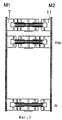
Фиг. 2 - устройство с множеством реле, соответствующее изобретению, без контактных средств. FIG. 2 - a device with many relays, corresponding to the invention, without contact means.
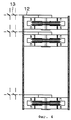
Фиг. 3 - устройство с множеством реле в возбужденном состоянии, выполненное согласно изобретению, без контактных средств. FIG. 3 - a device with many relays in an excited state, made according to the invention, without contact means.
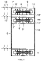
Фиг. 4 - устройство с множеством реле, соответствующее изобретению, с контактными средствами. FIG. 4 is a device with multiple relays, corresponding to the invention, with contact means.
Фиг. 5 - устройство с множеством реле в возбужденном состоянии, выполненное согласно изобретению, с возбужденными контактными средствами. FIG. 5 is a device with many relays in an excited state, made according to the invention, with excited contact means.
На фиг. 1 иллюстрируется известное решение, согласно которому множество реле 1, 2 ... n упорядочены в ряд в составе устройства с множеством реле. Каждая катушка 3 предназначена для возбуждения контактного средства 4, имеющего собственный рессорный комплект, причем сила, требуемая для этого, представлена силой F. Каждая катушка обеспечивает генерирование этой силы, а реально имеющая место сила равна n • F, где n - число имеющихся катушек, хотя реально для размыкания или замыкания переключателя нужна только сила F. In FIG. 1 illustrates a known solution, according to which a plurality of
В соответствии с настоящим изобретением различные функции реализуются в одном блоке. В данном аспекте устройство 5 с множеством реле содержит общую неподвижную часть 6, которая может быть снабжена постоянными магнитами 7 в количестве n, подвижные сердечники 8 в количестве n, причем каждый из них имеет возможность перемещения по отношению к неподвижной катушке 9, т.е. к неподвижной части 6, и общую подвижную часть 10, которая снабжена постоянными магнитами 11 в количестве n (см. фиг. 2, где n = ... 5, 6, 7 ... 10-40 . . .). Постоянные магниты обеспечивают определяемое так называемое исходное положение, в котором в цепь не подается ток. Это может быть достигнуто, не требуя использования пружин противодействия. В некоторых применениях постоянные магниты могут быть заменены на электромагниты. Неподвижная сторона 6 (M1), имеющая n постоянных магнитов 7, и подвижная сторона 10 (M2), имеющая n постоянных магнитов 11, могут быть поляризованы в соответствии с фиг. 2 где все воздушные зазоры между сердечниками и магнитами будут замкнуты, когда ток не подается в катушки. In accordance with the present invention, various functions are implemented in a single unit. In this aspect, the device 5 with many relays contains a common
Когда ток подается в цепь, содержащую катушки, для поляризации сердечников в соответствии с фиг. 3, все сердечники будут притягиваться стороной M1, за исключением сердечника nw, который теперь притягивается стороной M2. Сердечник nw будет отталкивать M1, а все другие сердечники будут отталкивать M2, тем самым используя силы от всех сердечников. Сила притяжения между сердечником nw и M2 весьма велика ввиду того, что в принципе воздушный зазор может быть нулевым. Таким образом, один или более сердечников можно заставить действовать совместно с соответствующими контактными элементами с помощью всех других сердечников, путем реверсирования полярности одной или более катушек. When current is supplied to the circuit containing the coils to polarize the cores in accordance with FIG. 3, all cores will be attracted by side M1, with the exception of core nw, which is now attracted by side M2. The core nw will repel M1, and all other cores will repel M2, thereby using forces from all cores. The force of attraction between the core nw and M2 is very large due to the fact that, in principle, the air gap can be zero. Thus, one or more cores can be made to act in conjunction with the corresponding contact elements using all other cores, by reversing the polarity of one or more coils.
Если подача тока прерывается, то все цепи будут способствовать возвращению сердечника (сердечников) в соответствующее исходное положение (положения). Поскольку сердечники в невозбужденных цепях не перемещаются, то отсутствуют потери на трение. If the current supply is interrupted, then all circuits will contribute to the return of the core (s) to the corresponding initial position (s). Since the cores in the unexcited chains do not move, there are no friction losses.
На фиг. 4 показано устройство с множеством реле, соответствующее изобретению, в состоянии покоя, соединенное с контактным средством 12 с разомкнутыми контактами 13 для соединения или разъединения проводников. На фиг. 5 показана катушка nw 9', соединенная с электрической цепью, и остальные катушки, соединенные с другой электрической цепью, которая имеет направление, противоположное первой цепи; сердечник 8' перемещается вправо, как показано на чертеже, и прерывает подачу тока 13' при ее совместном действии с контактным средством 12'. Сердечник 8' перемещается под действием силы отталкивания неподвижного постоянного магнита 7' и силы притяжения подвижного постоянного магнита 11'. Остальные сердечники 8 не перемещаются, поскольку они притягиваются неподвижными магнитами и отталкиваются подвижными постоянными магнитами 11. Объединенные магнитные силы перемещают подвижную часть 10 и сердечник 8' и контактное устройство 12', соединенные с ней. Неподвижные магниты 7 могут быть смонтированы в ряд на неподвижной раме 6, с которой могут также быть связаны катушки 9. Подвижные магниты 11 могут быть упорядочены в ряд на раме 10, которая является подвижной по отношению к неподвижной раме. Сердечники 8 и подвижная часть 10 могут перемещаться путем подачи тока в неподвижные катушки 9. In FIG. 4 shows a device with a plurality of relays according to the invention, at rest, connected to contact means 12 with
Сердечник (сердечники), которые перемещаются, будут инициировать функцию замыкания цепи, причем сердечники, которые не перемещаются, не будут влиять на функцию коммутации, т.е. цепи будут оставаться разомкнутыми, но сила отталкивания, действующая между этими сердечниками и подвижными магнитами, будет вносить вклад в перемещение контактов в контактном средстве. Магнитная сила n•f от всех электромагнитов с магнитной силой f необходима для замыкания тока в переключателе, где f может быть выбрано намного меньше, чем соответствующая сила F для индивидуальных контактных устройств с электромагнитным управлением. The core (s) that are moving will initiate the circuit closure function, and the cores that are not moving will not affect the switching function, i.e. the chains will remain open, but the repulsive force acting between these cores and the moving magnets will contribute to the movement of the contacts in the contact medium. The magnetic force n • f from all electromagnets with magnetic force f is needed to close the current in the switch, where f can be chosen much less than the corresponding force F for individual contact devices with electromagnetic control.
Claims (5)
Applications Claiming Priority (2)
| Application Number | Priority Date | Filing Date | Title |
|---|---|---|---|
| SE9503500-2 | 1995-10-09 | ||
| SE9503500A SE514996C2 (en) | 1995-10-09 | 1995-10-09 | A method for providing multiple relay functions and a multiple relay device arranged according to the method |
Publications (2)
| Publication Number | Publication Date |
|---|---|
| RU98108543A RU98108543A (en) | 2000-04-10 |
| RU2168232C2 true RU2168232C2 (en) | 2001-05-27 |
Family
ID=20399747
Family Applications (1)
| Application Number | Title | Priority Date | Filing Date |
|---|---|---|---|
| RU98108543/09A RU2168232C2 (en) | 1995-10-09 | 1996-10-08 | Method and multiple-relay device for furnishing various change-over functions |
Country Status (19)
| Country | Link |
|---|---|
| US (1) | US6249420B1 (en) |
| EP (1) | EP0856192B1 (en) |
| JP (1) | JP2000500904A (en) |
| KR (1) | KR19990064108A (en) |
| CN (1) | CN1080448C (en) |
| AT (1) | ATE205959T1 (en) |
| AU (1) | AU709879B2 (en) |
| BR (1) | BR9611054A (en) |
| CA (1) | CA2233649A1 (en) |
| DE (1) | DE69615386D1 (en) |
| DK (1) | DK0856192T3 (en) |
| ES (1) | ES2162097T3 (en) |
| HU (1) | HUP9900098A3 (en) |
| NO (1) | NO981479L (en) |
| PL (1) | PL326073A1 (en) |
| RU (1) | RU2168232C2 (en) |
| SE (1) | SE514996C2 (en) |
| TW (1) | TW319878B (en) |
| WO (1) | WO1997014167A1 (en) |
Families Citing this family (1)
| Publication number | Priority date | Publication date | Assignee | Title |
|---|---|---|---|---|
| ES2144361B1 (en) * | 1998-03-17 | 2001-01-01 | Invest Y Transferencia De Tecn | REMOTE SWITCHING DEVICE. |
Family Cites Families (7)
| Publication number | Priority date | Publication date | Assignee | Title |
|---|---|---|---|---|
| CH46807A (en) | 1909-03-13 | 1910-04-16 | Henri Jaccoud | Device on the door leaves, operating automatically when the doors are closed, with the aim of obtaining, without threshold, a good closing of their lower part |
| DE1301839B (en) | 1965-09-30 | 1969-08-28 | Siemens Ag | Magnetically operated switching device for polarized operation |
| DE1954952B2 (en) | 1969-10-31 | 1971-11-18 | RELAY KIT | |
| US5264812A (en) * | 1992-05-19 | 1993-11-23 | Takamisawa Electric Co., Ltd. | Small, economical and stable polarized electromagnetic relay having two groups of electromagnetic relay portions |
| SE9202320L (en) * | 1992-08-10 | 1994-02-11 | Sivers Ima Ab | switching device |
| GB2273526B (en) * | 1992-12-17 | 1996-08-21 | Euromond Ltd | Stays |
| JP3575707B2 (en) * | 1995-03-13 | 2004-10-13 | 松下電工株式会社 | Matrix relay |
-
1995
- 1995-10-09 SE SE9503500A patent/SE514996C2/en not_active IP Right Cessation
-
1996
- 1996-10-03 TW TW085112103A patent/TW319878B/zh not_active IP Right Cessation
- 1996-10-08 BR BR9611054A patent/BR9611054A/en not_active IP Right Cessation
- 1996-10-08 HU HU9900098A patent/HUP9900098A3/en unknown
- 1996-10-08 WO PCT/SE1996/001272 patent/WO1997014167A1/en active IP Right Grant
- 1996-10-08 EP EP96933722A patent/EP0856192B1/en not_active Expired - Lifetime
- 1996-10-08 US US09/051,108 patent/US6249420B1/en not_active Expired - Lifetime
- 1996-10-08 AT AT96933722T patent/ATE205959T1/en not_active IP Right Cessation
- 1996-10-08 ES ES96933722T patent/ES2162097T3/en not_active Expired - Lifetime
- 1996-10-08 CA CA002233649A patent/CA2233649A1/en not_active Abandoned
- 1996-10-08 CN CN96197487A patent/CN1080448C/en not_active Expired - Fee Related
- 1996-10-08 JP JP9514982A patent/JP2000500904A/en active Pending
- 1996-10-08 DE DE69615386T patent/DE69615386D1/en not_active Expired - Lifetime
- 1996-10-08 RU RU98108543/09A patent/RU2168232C2/en active
- 1996-10-08 AU AU72344/96A patent/AU709879B2/en not_active Ceased
- 1996-10-08 DK DK96933722T patent/DK0856192T3/en active
- 1996-10-08 PL PL96326073A patent/PL326073A1/en unknown
- 1996-10-08 KR KR1019980702589A patent/KR19990064108A/en active IP Right Grant
-
1998
- 1998-04-01 NO NO981479A patent/NO981479L/en not_active Application Discontinuation
Also Published As
| Publication number | Publication date |
|---|---|
| NO981479D0 (en) | 1998-04-01 |
| CN1199499A (en) | 1998-11-18 |
| US6249420B1 (en) | 2001-06-19 |
| DK0856192T3 (en) | 2001-12-17 |
| ATE205959T1 (en) | 2001-10-15 |
| PL326073A1 (en) | 1998-08-17 |
| HUP9900098A2 (en) | 1999-04-28 |
| CA2233649A1 (en) | 1997-04-17 |
| SE9503500L (en) | 1997-04-10 |
| SE9503500D0 (en) | 1995-10-09 |
| DE69615386D1 (en) | 2001-10-25 |
| HUP9900098A3 (en) | 1999-11-29 |
| CN1080448C (en) | 2002-03-06 |
| EP0856192A1 (en) | 1998-08-05 |
| MX9802271A (en) | 1998-08-30 |
| SE514996C2 (en) | 2001-05-28 |
| EP0856192B1 (en) | 2001-09-19 |
| WO1997014167A1 (en) | 1997-04-17 |
| AU709879B2 (en) | 1999-09-09 |
| JP2000500904A (en) | 2000-01-25 |
| ES2162097T3 (en) | 2001-12-16 |
| KR19990064108A (en) | 1999-07-26 |
| TW319878B (en) | 1997-11-11 |
| AU7234496A (en) | 1997-04-30 |
| NO981479L (en) | 1998-04-01 |
| BR9611054A (en) | 1999-07-06 |
Similar Documents
| Publication | Publication Date | Title |
|---|---|---|
| US4994776A (en) | Magnetic latching solenoid | |
| DE69415819T2 (en) | BISTABLE MAGNETIC ACTUATOR | |
| WO2010014213A1 (en) | Switching device | |
| ES2147991T3 (en) | ELECTRIC SWITCH WITH A MAGNETIC OPERATION. | |
| US4609899A (en) | Polarized electromagnet having three states and a control circuit for said electromagnet | |
| US5949315A (en) | Polarized relay | |
| US3184563A (en) | Magnetically controlled reed switching device | |
| EP0179911A1 (en) | Electromagnetic actuator apparatus | |
| RU2168232C2 (en) | Method and multiple-relay device for furnishing various change-over functions | |
| CA1283680C (en) | Microwave c-switches and s-switches | |
| DE69603026D1 (en) | POLARIZED ELECTROMAGNETIC RELAY | |
| CA2182931C (en) | Switching field | |
| MXPA98002271A (en) | A method of fixing various functions of relay yuna provision of multiple relay configured in accordance with met | |
| US3919676A (en) | Permanent-magnet type relay | |
| JPS58181227A (en) | Polarized electromagnetic relay | |
| RU98108543A (en) | METHOD FOR ENSURING DIFFERENT SWITCHING FUNCTIONS AND DEVICE WITH MANY RELAYS EXECUTED IN ACCORDANCE WITH THE METHOD | |
| GB2127224A (en) | A contactor for the control of electric motors | |
| EP0094753A1 (en) | Electromagnetic actuator | |
| SU1140185A1 (en) | A.c.switching device | |
| JPH03222230A (en) | Electromagnetic relay | |
| JPS58154127A (en) | Electromagnetic relay | |
| JPH03236135A (en) | Polarized electromagnetic relay | |
| WO2004017339A1 (en) | Magnetic actuator or relay |