RU2166964C2 - Device for carrying out peritoneal dialysis - Google Patents
Device for carrying out peritoneal dialysis Download PDFInfo
- Publication number
- RU2166964C2 RU2166964C2 RU96117471/14A RU96117471A RU2166964C2 RU 2166964 C2 RU2166964 C2 RU 2166964C2 RU 96117471/14 A RU96117471/14 A RU 96117471/14A RU 96117471 A RU96117471 A RU 96117471A RU 2166964 C2 RU2166964 C2 RU 2166964C2
- Authority
- RU
- Russia
- Prior art keywords
- pressure
- casing
- pump
- bag
- patient
- Prior art date
Links
Images

Classifications
-
- A—HUMAN NECESSITIES
- A61—MEDICAL OR VETERINARY SCIENCE; HYGIENE
- A61M—DEVICES FOR INTRODUCING MEDIA INTO, OR ONTO, THE BODY; DEVICES FOR TRANSDUCING BODY MEDIA OR FOR TAKING MEDIA FROM THE BODY; DEVICES FOR PRODUCING OR ENDING SLEEP OR STUPOR
- A61M1/00—Suction or pumping devices for medical purposes; Devices for carrying-off, for treatment of, or for carrying-over, body-liquids; Drainage systems
- A61M1/14—Dialysis systems; Artificial kidneys; Blood oxygenators ; Reciprocating systems for treatment of body fluids, e.g. single needle systems for hemofiltration or pheresis
- A61M1/28—Peritoneal dialysis ; Other peritoneal treatment, e.g. oxygenation
-
- A—HUMAN NECESSITIES
- A61—MEDICAL OR VETERINARY SCIENCE; HYGIENE
- A61M—DEVICES FOR INTRODUCING MEDIA INTO, OR ONTO, THE BODY; DEVICES FOR TRANSDUCING BODY MEDIA OR FOR TAKING MEDIA FROM THE BODY; DEVICES FOR PRODUCING OR ENDING SLEEP OR STUPOR
- A61M1/00—Suction or pumping devices for medical purposes; Devices for carrying-off, for treatment of, or for carrying-over, body-liquids; Drainage systems
- A61M1/14—Dialysis systems; Artificial kidneys; Blood oxygenators ; Reciprocating systems for treatment of body fluids, e.g. single needle systems for hemofiltration or pheresis
- A61M1/16—Dialysis systems; Artificial kidneys; Blood oxygenators ; Reciprocating systems for treatment of body fluids, e.g. single needle systems for hemofiltration or pheresis with membranes
- A61M1/1621—Constructional aspects thereof
- A61M1/1643—Constructional aspects thereof with weighing of fresh and used dialysis fluid
-
- A—HUMAN NECESSITIES
- A61—MEDICAL OR VETERINARY SCIENCE; HYGIENE
- A61M—DEVICES FOR INTRODUCING MEDIA INTO, OR ONTO, THE BODY; DEVICES FOR TRANSDUCING BODY MEDIA OR FOR TAKING MEDIA FROM THE BODY; DEVICES FOR PRODUCING OR ENDING SLEEP OR STUPOR
- A61M1/00—Suction or pumping devices for medical purposes; Devices for carrying-off, for treatment of, or for carrying-over, body-liquids; Drainage systems
- A61M1/14—Dialysis systems; Artificial kidneys; Blood oxygenators ; Reciprocating systems for treatment of body fluids, e.g. single needle systems for hemofiltration or pheresis
- A61M1/28—Peritoneal dialysis ; Other peritoneal treatment, e.g. oxygenation
- A61M1/281—Instillation other than by gravity
-
- A—HUMAN NECESSITIES
- A61—MEDICAL OR VETERINARY SCIENCE; HYGIENE
- A61M—DEVICES FOR INTRODUCING MEDIA INTO, OR ONTO, THE BODY; DEVICES FOR TRANSDUCING BODY MEDIA OR FOR TAKING MEDIA FROM THE BODY; DEVICES FOR PRODUCING OR ENDING SLEEP OR STUPOR
- A61M1/00—Suction or pumping devices for medical purposes; Devices for carrying-off, for treatment of, or for carrying-over, body-liquids; Drainage systems
- A61M1/60—Containers for suction drainage, adapted to be used with an external suction source
- A61M1/604—Bag or liner in a rigid container, with suction applied to both
-
- A—HUMAN NECESSITIES
- A61—MEDICAL OR VETERINARY SCIENCE; HYGIENE
- A61M—DEVICES FOR INTRODUCING MEDIA INTO, OR ONTO, THE BODY; DEVICES FOR TRANSDUCING BODY MEDIA OR FOR TAKING MEDIA FROM THE BODY; DEVICES FOR PRODUCING OR ENDING SLEEP OR STUPOR
- A61M2205/00—General characteristics of the apparatus
- A61M2205/07—General characteristics of the apparatus having air pumping means
-
- A—HUMAN NECESSITIES
- A61—MEDICAL OR VETERINARY SCIENCE; HYGIENE
- A61M—DEVICES FOR INTRODUCING MEDIA INTO, OR ONTO, THE BODY; DEVICES FOR TRANSDUCING BODY MEDIA OR FOR TAKING MEDIA FROM THE BODY; DEVICES FOR PRODUCING OR ENDING SLEEP OR STUPOR
- A61M2205/00—General characteristics of the apparatus
- A61M2205/60—General characteristics of the apparatus with identification means
- A61M2205/6063—Optical identification systems
- A61M2205/6081—Colour codes
-
- A—HUMAN NECESSITIES
- A61—MEDICAL OR VETERINARY SCIENCE; HYGIENE
- A61M—DEVICES FOR INTRODUCING MEDIA INTO, OR ONTO, THE BODY; DEVICES FOR TRANSDUCING BODY MEDIA OR FOR TAKING MEDIA FROM THE BODY; DEVICES FOR PRODUCING OR ENDING SLEEP OR STUPOR
- A61M5/00—Devices for bringing media into the body in a subcutaneous, intra-vascular or intramuscular way; Accessories therefor, e.g. filling or cleaning devices, arm-rests
- A61M5/14—Infusion devices, e.g. infusing by gravity; Blood infusion; Accessories therefor
- A61M5/142—Pressure infusion, e.g. using pumps
- A61M5/145—Pressure infusion, e.g. using pumps using pressurised reservoirs, e.g. pressurised by means of pistons
- A61M5/148—Pressure infusion, e.g. using pumps using pressurised reservoirs, e.g. pressurised by means of pistons flexible, e.g. independent bags
- A61M5/1483—Pressure infusion, e.g. using pumps using pressurised reservoirs, e.g. pressurised by means of pistons flexible, e.g. independent bags using flexible bags externally pressurised by fluid pressure
- A61M5/1486—Pressure infusion, e.g. using pumps using pressurised reservoirs, e.g. pressurised by means of pistons flexible, e.g. independent bags using flexible bags externally pressurised by fluid pressure the bags being substantially completely surrounded by fluid
-
- Y—GENERAL TAGGING OF NEW TECHNOLOGICAL DEVELOPMENTS; GENERAL TAGGING OF CROSS-SECTIONAL TECHNOLOGIES SPANNING OVER SEVERAL SECTIONS OF THE IPC; TECHNICAL SUBJECTS COVERED BY FORMER USPC CROSS-REFERENCE ART COLLECTIONS [XRACs] AND DIGESTS
- Y10—TECHNICAL SUBJECTS COVERED BY FORMER USPC
- Y10S—TECHNICAL SUBJECTS COVERED BY FORMER USPC CROSS-REFERENCE ART COLLECTIONS [XRACs] AND DIGESTS
- Y10S128/00—Surgery
- Y10S128/12—Pressure infusion
-
- Y—GENERAL TAGGING OF NEW TECHNOLOGICAL DEVELOPMENTS; GENERAL TAGGING OF CROSS-SECTIONAL TECHNOLOGIES SPANNING OVER SEVERAL SECTIONS OF THE IPC; TECHNICAL SUBJECTS COVERED BY FORMER USPC CROSS-REFERENCE ART COLLECTIONS [XRACs] AND DIGESTS
- Y10—TECHNICAL SUBJECTS COVERED BY FORMER USPC
- Y10S—TECHNICAL SUBJECTS COVERED BY FORMER USPC CROSS-REFERENCE ART COLLECTIONS [XRACs] AND DIGESTS
- Y10S128/00—Surgery
- Y10S128/13—Infusion monitoring
Landscapes
- Health & Medical Sciences (AREA)
- Urology & Nephrology (AREA)
- Heart & Thoracic Surgery (AREA)
- Emergency Medicine (AREA)
- Anesthesiology (AREA)
- Engineering & Computer Science (AREA)
- Vascular Medicine (AREA)
- Biomedical Technology (AREA)
- Hematology (AREA)
- Life Sciences & Earth Sciences (AREA)
- Animal Behavior & Ethology (AREA)
- General Health & Medical Sciences (AREA)
- Public Health (AREA)
- Veterinary Medicine (AREA)
- External Artificial Organs (AREA)
Abstract
Description
Настоящее изобретение относится к устройству для введения больному раствора для перитонеального диализа, подобное устройство известно как прибор, обеспечивающий цикл ПД. The present invention relates to a device for administering a peritoneal dialysis solution to a patient, a similar device is known as a device providing a PD cycle.
ПРЕДШЕСТВУЮЩИЙ УРОВЕНЬ ТЕХНИКИ
Изобретение берет начало с технологии, использованной заявителем в системе ГАМБРО ПД 100. Эта система включает штатив высотой около 2 метров. На первом верхнем уровне, у верхнего конца штатива, имеются крючки для подвешивания мешков, содержащих готовую к употреблению смесь раствора, подаваемого для перитонеального диализа. Мешки подачи раствора соединены посредством трубок с мешком нагрева, расположенным непосредственно ниже мешков подачи раствора на втором промежуточном уровне. Мешок нагрева расположен на нагревающей поверхности прибора для взвешивания.BACKGROUND OF THE INVENTION
The invention originates from the technology used by the applicant in the GAMBRO PD 100 system. This system includes a tripod about 2 meters high. At the first upper level, at the upper end of the tripod, there are hooks for hanging bags containing a ready-to-use mixture of the solution supplied for peritoneal dialysis. The solution supply bags are connected via tubes to a heating bag located immediately below the solution supply bags at a second intermediate level. The heating bag is located on the heating surface of the weighing device.
Мешок нагрева заполняется под контролем клапанов из мешков подачи раствора и может иметь объем около 2 литров или несколько больше. Когда содержимое мешка нагрева достигает нужной температуры, оно под действием силы тяжести направляется в катетер, конец которого находится в брюшной полости больного. Катетер и брюшная полость находятся на третьем уровне, который ниже второго уровня. The heating bag is filled under the control of the valves from the solution supply bags and may have a volume of about 2 liters or more. When the contents of the heating bag reaches the desired temperature, it is directed by gravity to a catheter, the end of which is in the patient’s abdominal cavity. The catheter and abdominal cavity are on the third level, which is below the second level.
После того как раствор для диализа выполнит свою задачу, он дренируется в мешок слива, расположенный на четвертом уровне. Мешок слива прикреплен к системе крючков, которая висит на приборе для взвешивания для мешка нагрева. Таким образом, один и тот же взвешивающий элемент или тензодатчик используется для взвешивания мешка нагрева, а также мешка слива. Содержимое мешка слива в конечном итоге дренируется либо прямо в канализацию или в накопительные мешки, которые расположены на пятом и самом низком уровне. Все движение раствора происходит между пятью различными уровнями под влиянием силы тяжести. Поэтому очевидна важность расположения больного на определенном уровне ниже мешка нагрева и выше мешка слива. After the dialysis solution has completed its task, it is drained into a drain bag located on the fourth level. The drain bag is attached to the hook system that hangs on the weighing device for the heating bag. Thus, the same weighing element or load cell is used to weigh the heating bag as well as the drain bag. The contents of the drain bag ultimately drain either directly into the sewer or into the collection bags, which are located at the fifth and lowest level. All movement of the solution occurs between five different levels under the influence of gravity. Therefore, the importance of locating the patient at a certain level below the heating bag and above the drain bag is obvious.
Набор трубок, предназначенных для использования в системе ГАМБРО ПД 100, показан в EP-A1-499718. A set of tubes for use in the GAMBRO PD 100 system is shown in EP-A1-499718.
Аналогичная циклическая система описана в патенте US-A-5141492, в которой используются только три уровня. В этом случае количество входящего раствора не взвешивается, а определяется только по размеру мешков подачи раствора. Мешки подачи раствора нагреваются непосредственно до соответствующей температуры. Для сбора раствора также используется мешок слива, и его размеры делаются достаточно большими. Взвешивается только накопительный мешок. A similar cyclic system is described in US-A-5141492, which uses only three levels. In this case, the amount of the incoming solution is not weighed, but is determined only by the size of the solution supply bags. The solution bags are heated directly to the appropriate temperature. A drain bag is also used to collect the solution, and its dimensions are made large enough. Only the storage bag is weighed.
Для того чтобы избежать зависимости от силы тяжести для подачи диализного раствора, было предложено использование насосов. Такой насос описан в патенте US-A-4412917 в виде перистальтического насоса для подачи диализного раствора больному из резервуара подачи раствора, расположенного на уровне пола. Прибор для измерения давления гарантирует, что давление в катетере не превышает предварительно установленного значения. Резервуар подачи раствора, а также накопительный резервуар располагаются на приборе для взвешивания для контроля за входом и выходом раствора для диализа к больному и от него. In order to avoid dependence on gravity for feeding the dialysis solution, the use of pumps has been proposed. Such a pump is described in US-A-4,412,917 as a peristaltic pump for supplying a dialysis solution to a patient from a solution supply tank located at floor level. The pressure measuring device ensures that the pressure in the catheter does not exceed a preset value. The solution supply tank, as well as the storage tank, are located on the weighing device to control the inlet and outlet of the dialysis solution to and from the patient.
В патенте US-A-4560472 описывается насос для перекачки подаваемого раствора с первого уровня к мешку нагрева, расположенному на более высоком уровне. Последующий транспорт диализного раствора происходит затем под влиянием силы тяжести. Таким образом избегают необходимость поднимать тяжелые мешки подачи раствора на высокий уровень. US-A-4,560,472 describes a pump for pumping a feed solution from a first level to a heating bag located at a higher level. Subsequent transport of the dialysis solution then occurs under the influence of gravity. In this way, the need to raise heavy solution bags to a high level is avoided.
В патенте US-A-5004459 описывается еще более автоматизированная система введения ПД-раствора. Устройство включает отдельный насос для заполнения брюшной полости и отдельный выводной насос для откачки раствора из брюшной полости. Два датчика давления и/или потока определяют и ограничивают давление и/или поток подачи или откачки. Устройство также предусматривает смешивание диализных концентратов с чистой водой, возможно, с добавлением глюкозы. US-A-5004459 describes an even more automated PD solution administration system. The device includes a separate pump for filling the abdominal cavity and a separate outlet pump for pumping the solution from the abdominal cavity. Two pressure and / or flow sensors detect and limit the pressure and / or flow of the supply or pumping. The device also provides for mixing dialysis concentrates with pure water, possibly with the addition of glucose.
В патенте US-A-4311587 описано устройство для подачи диализного раствора через стерильный фильтр, для того чтобы избежать перитонита, путем фильтрации входящего раствора. Поскольку стерильный фильтр создает высокое сопротивление потоку, требуется более высокое давление, чем то, которого можно практически достичь под влиянием силы тяжести. Поэтому мешок, содержащий диализный раствор, помещается на ремне под предплечье, и предплечьем или локтем производится сдавливание мешка с целью продавливания диализного раствора через стерильный фильтр и через катетер в брюшную полость. Отток происходит под влиянием силы тяжести. В этой конструкции используются однонаправленные клапаны. US-A-4311587 describes a device for feeding a dialysis solution through a sterile filter, in order to avoid peritonitis, by filtering the incoming solution. Since the sterile filter creates a high flow resistance, a higher pressure is required than that which can be practically achieved under the influence of gravity. Therefore, the bag containing the dialysis solution is placed on the belt under the forearm, and the bag is squeezed with the forearm or elbow to push the dialysis solution through the sterile filter and through the catheter into the abdominal cavity. Outflow occurs under the influence of gravity. Unidirectional valves are used in this design.
В патенте US-A-5141493 описана система, в которой используются насос и датчик давления для подачи и откачки диализного раствора у больного. Затем диализный раствор направляется в первичный контур циркуляции через диализатор, который в свою очередь соединен со вторичным контуром, посредством чего диализный раствор в первом контуре очищается с помощью упомянутого диализатора. US-A-5141493 describes a system in which a pump and a pressure sensor are used to supply and pump out a dialysis solution in a patient. The dialysis solution is then sent to the primary circulation loop through a dialyzer, which in turn is connected to the secondary circuit, whereby the dialysis solution in the first loop is cleaned with the said dialyzer.
В патенте WO 90/13795 описывается насос, использование которого предполагается в связи с перитонеальным диализом. Насос состоит из камеры, разделенной эластической мембраной. С одной стороны мембраны находится раствор, подлежащий перекачиванию, а с другой стороны мембраны находится газ. Положительное и отрицательное давление подается в камеру с помощью газа. Перекачиваемый объем контролируется и измеряется путем измерения объема газа в камере для газа. WO 90/13795 describes a pump, the use of which is contemplated in connection with peritoneal dialysis. The pump consists of a chamber separated by an elastic membrane. On one side of the membrane is the solution to be pumped, and on the other side of the membrane is gas. Positive and negative pressure is supplied to the chamber using gas. The pumped volume is monitored and measured by measuring the volume of gas in the gas chamber.
В патенте EP-A1-94682 описывается устройство для реинфузии крови, включающее сосуд, имеющий регидные стенки и содержащий в себе гибкий резервуар. Кровь поступает в гибкий резервуар под влиянием разрежения, создаваемого в пространстве между резервуаром и сосудом. Затем осуществляется реинфузия крови при создании избыточного давления в пространстве между резервуаром и сосудом. Patent EP-A1-94682 describes a device for blood reinfusion, including a vessel having reid walls and comprising a flexible reservoir. Blood enters the flexible reservoir under the influence of the vacuum created in the space between the reservoir and the vessel. Then, blood reinfusion is performed when excessive pressure is created in the space between the reservoir and the vessel.
РАСКРЫТИЕ ИЗОБРЕТЕНИЯ
В основу настоящего изобретения положена задача создания устройства для перитонеального диализа, в котором подача и/или удаление диализного раствора больному и/или от него происходит полностью или частично без влияния силы тяжести, т.е. с помощью насосов. Таким образом, больной может принимать различные положения по отношению к устройству, не влияя на работу устройства. К тому же можно использовать более высокое давление, чем то, которое практически возможно при подаче под влиянием силы тяжести, что уменьшает время подачи и удаления. В то же самое время скорость потока можно подобрать в соответствии с потребностями определенного больного.SUMMARY OF THE INVENTION
The basis of the present invention is the creation of a device for peritoneal dialysis, in which the supply and / or removal of the dialysis solution to the patient and / or from him occurs in whole or in part without the influence of gravity, i.e. using pumps. Thus, the patient can take various positions in relation to the device without affecting the operation of the device. In addition, you can use a higher pressure than that which is practically possible when feeding under the influence of gravity, which reduces the time of supply and removal. At the same time, the flow rate can be selected in accordance with the needs of a particular patient.
Второй задачей, решаемой данным изобретением, является создание такого насоса, который был бы безопасен и удобен в использовании и который достаточно бесшумен для работы в ночное время. The second task solved by this invention is the creation of such a pump, which would be safe and convenient to use and which is noiseless enough to work at night.
Еще одной задачей, решаемой данным изобретением, является упрощение набора трубок, который требуется для работы устройства для перитонеального диализа. Another objective solved by this invention is to simplify the set of tubes that is required for the operation of the device for peritoneal dialysis.
Желательно получить насосную функцию без использования насоса, который будет загрязнен диализным раствором. Очевидным объектом выбора является, например, перистальтический насос (как показано в патенте US-A-4412917), который воздействует на трубки в системе, сам не становясь загрязненным раствором. It is advisable to obtain a pumping function without using a pump that will be contaminated with dialysis solution. An obvious choice is, for example, a peristaltic pump (as shown in US-A-4,412,917), which acts on the tubes in the system without becoming a contaminated solution itself.
В этой связи отмечено, что диализный раствор проходит через и нагревается мешком нагрева в ранее известной системе ПД 100. В соответствии с настоящим изобретением подобный мешок нагрева используется как часть насосного блока путем воздействия на мешок нагрева избыточным давлением и/или разрежением. Поток к мешку нагрева и от него постоянно контролируется с помощью прибора для взвешивания. In this regard, it is noted that the dialysis solution passes through and is heated by a heating bag in the previously known PD 100 system. In accordance with the present invention, such a heating bag is used as part of a pumping unit by exposing the heating bag to excessive pressure and / or vacuum. The flow to and from the heating bag is constantly monitored using a weighing instrument.
Таким образом, изобретение относится к устройству для проведения перитонеального диализа, содержащему прибор для взвешивания, приспособленный для взвешивания содержимого первого гибкого резервуара, подобного мешку нагрева, который соединен по крайней мере с одним трубопроводом в качестве выпускного канала и, возможно, даже в качестве впускного канала для раствора из резервуара. В соответствии с изобретением устройство содержит кожух, который установлен вокруг резервуара таким образом, что между кожухом и контейнером образуется пространство, а контейнер включает приспособление ввода для проведения трубопровода через кожух. Устройство также содержит компрессор, приспособленный для сдавливания резервуара для его опорожнения. Thus, the invention relates to a device for conducting peritoneal dialysis, comprising a weighing device adapted to weigh the contents of a first flexible reservoir, such as a heating bag, which is connected to at least one conduit as an outlet channel and possibly even as an inlet channel for solution from the tank. In accordance with the invention, the device comprises a casing, which is installed around the tank so that between the casing and the container space is formed, and the container includes an input device for passing the pipeline through the casing. The device also includes a compressor adapted to squeeze the tank to empty it.
Устройство соответственно содержит приспособление для подачи вещества, передающего давление, под избыточным давлением и/или пониженным давлением в пространстве между кожухом и резервуаром, причем указанное пространство является закрытым. Предпочтительно изготовление кожуха из ригидного материала. The device accordingly comprises a device for supplying a pressure transmitting substance under overpressure and / or reduced pressure in the space between the casing and the tank, said space being closed. Preferably the manufacture of a casing of rigid material.
Подходящим веществом для передачи давления является газ, например, воздух, но оно может также быть жидкостью, например, водой. Кожух может состоять из нижней части и верхней части. Нижняя часть образует шкалу взвешивания и соединена с прибором для взвешивания. Верхнюю часть можно отогнуть или снять с нижней части, причем обычно обе части плотно скреплены друг с другом. Кожух соединен с блоком насоса для нагнетения передающего давление вещества вовнутрь и/или его удаления из пространства между кожухом и резервуаром. A suitable substance for transmitting pressure is a gas, for example, air, but it can also be a liquid, for example, water. The casing may consist of a lower part and an upper part. The lower part forms a weighing scale and is connected to a weighing device. The upper part can be bent or removed from the lower part, and usually both parts are tightly bonded to each other. The casing is connected to the pump unit to pump the pressure-transmitting substance inward and / or to remove it from the space between the casing and the reservoir.
Кожух может также содержать второй гибкий резервуар, снабженный трубопроводом для впускного и/или выпускного канала использованного или израсходованного раствора, причем первый резервуар предназначен для свежего раствора. Наряду с этим имеется система клапанов, регулирующих направление потока в сторону и от резервуаров, преимущественно являющихся пластиковыми мешками. The casing may also comprise a second flexible reservoir provided with a conduit for the inlet and / or outlet of the used or consumed solution, the first reservoir being for fresh solution. Along with this, there is a system of valves that regulate the direction of flow to and from the tanks, which are mainly plastic bags.
Блок насоса может состоять из насоса центрифужного типа, который достигает заданное давление в своем выпускном канале и может менять направление потока в обратную сторону для достижения указанного разрежения. В качестве альтернативы насос может быть мембранным насосом, регулируемым датчиком давления. Еще одной альтернативой может быть использование двух напорных камер для создания избыточного давления и разрежения, причем полость кожуха последовательно соединена с соответствующими напорными камерами. Насос может работать более или менее продолжительно и создавать давление в напорных камерах. Прибор, контролирующий давление, используется для наблюдения и регулировки давления. The pump unit may consist of a centrifugal pump, which reaches a predetermined pressure in its outlet channel and can change the direction of flow in the opposite direction to achieve the specified vacuum. Alternatively, the pump may be a diaphragm pump controlled by a pressure sensor. Another alternative may be the use of two pressure chambers to create excess pressure and vacuum, and the cavity of the casing is connected in series with the corresponding pressure chambers. The pump can operate more or less continuously and create pressure in the pressure chambers. A pressure monitoring device is used to monitor and adjust pressure.
Имеется много преимуществ настоящего изобретения по сравнению с предшествующими аналогами. There are many advantages of the present invention compared to the prior art.
1. Больше не требуется подъем тяжелых резервуаров с диализным раствором на большую высоту. 1. No longer requires lifting heavy tanks with dialysis solution to a high height.
2. Мешок нагрева может заполняться быстрее, поскольку давление во время этого процесса может быть выше. 2. The heating bag may fill up faster, because the pressure during this process may be higher.
3. Мешок слива может опорожняться в приемник стока, расположенный на более высоком уровне. 3. The drain bag can be emptied into a drain receiver located at a higher level.
4. В содержимом мешка слива имеются шлаковые продукты, такие как фибриновые преципитаты и т.д., которые повышают вязкость жидкости, но при использовании более высокого давления нагнетения удаление может происходить быстрее. 4. The contents of the drain bag contain slag products, such as fibrin precipitates, etc., which increase the viscosity of the liquid, but when using a higher discharge pressure, removal can be faster.
5. Как давление подачи, так и давление удаления раствора из брюшной полости больного можно регулировать в соответствии с комфортностью ощущений больного. 5. Both the supply pressure and the removal pressure of the solution from the patient’s abdominal cavity can be adjusted in accordance with the comfort of the patient’s sensations.
6. Диализный раствор всегда находится внутри мешков и трубок, которые могут изготавливаться из дешевого пластикового материала в соответствии с известными технологиями. В соответствии с изобретением, компоненты насоса воздействуют только на наружные поверхности этих мешков. ПД-раствор все время находится в закрытой системе. 6. Dialysis solution is always located inside bags and tubes, which can be made from cheap plastic material in accordance with known technologies. In accordance with the invention, the components of the pump act only on the outer surfaces of these bags. PD solution is always in a closed system.
7. В соответствии с изобретением устройство является простым и может изготавливаться в компактном и легком исполнении, что облегчает его транспортировку. 7. In accordance with the invention, the device is simple and can be manufactured in a compact and lightweight design, which facilitates its transportation.
8. Устройство характеризуется высокой гибкостью в эксплуатации, и в нем могут использоваться комбинации принудительной подачи и подачи под влиянием силы тяжести. 8. The device is characterized by high flexibility in operation, and combinations of forced feeding and feeding under the influence of gravity can be used in it.
9. В соответствии с изобретением устройство может работать без существенного потребления энергии. Потребление энергии можно дополнительно снизить таким образом, что устройство, например при отключении электроэнергии, может работать более продолжительное время с использованием запасного источника питания, как, например, батарейки. 9. In accordance with the invention, the device can operate without significant energy consumption. Energy consumption can be further reduced in such a way that the device, for example during a power outage, can operate for a longer time using a spare power source, such as batteries.
10. Дополнительная экономия энергии может быть достигнута посредством теплообмена теплого диализного раствора в мешке слива с более холодным свежим ПД-раствором в мешке нагрева. 10. Additional energy savings can be achieved by heat exchange of the warm dialysis solution in the drain bag with a cooler fresh PD solution in the heating bag.
КРАТКОЕ ОПИСАНИЕ ЧЕРТЕЖЕЙ
В дальнейшем изобретение поясняется конкретным вариантом его выполнения со ссылкой на сопровождающие чертежи, на которых:
Фиг. 1 изображает перспективу прибора, обеспечивающего цикл ПД в соответствии с ранее известной системой заявителя ГАМБРО ПД 100.BRIEF DESCRIPTION OF THE DRAWINGS
The invention is further illustrated by a specific embodiment with reference to the accompanying drawings, in which:
FIG. 1 shows a perspective view of an apparatus providing a PD cycle in accordance with a previously known applicant system GAMBRO PD 100.
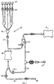
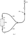
Фиг. 2 - вид сбоку набора трубок для использования в системе ГАМБРО ПД 100. FIG. 2 is a side view of a set of tubes for use in the GAMBRO PD 100 system.
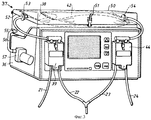
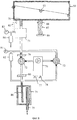
Фиг. 3 - перспективу устройства в соответствии с изобретением. FIG. 3 is a perspective view of a device in accordance with the invention.
Фиг. 4 - вид, аналогичный таковому на фиг. 3, альтернативного устройства в соответствии с изобретением. FIG. 4 is a view similar to that of FIG. 3, an alternative device in accordance with the invention.
Фиг. 5 - вид сбоку набора трубок для использования с устройством в соответствии с настоящим изобретением. FIG. 5 is a side view of a set of tubes for use with a device in accordance with the present invention.
Фиг. 6 - вид сбоку альтернативного набора трубок. FIG. 6 is a side view of an alternative set of tubes.
Фиг. 7 - вид сбоку упрощенного набора трубок. FIG. 7 is a side view of a simplified set of tubes.
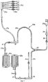
Фиг. 8 является схематическим изображением предпочтительного блока насоса для устройства в соответствии с изобретением. FIG. 8 is a schematic diagram of a preferred pump unit for a device in accordance with the invention.
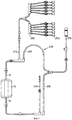
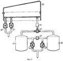
Фиг. 9 является схематическим изображением второго блока насоса для устройства в соответствии с изобретением. FIG. 9 is a schematic representation of a second pump unit for a device in accordance with the invention.
ВАРИАНТ НАИЛУЧШЕГО ОСУЩЕСТВЛЕНИЯ ИЗОБРЕТЕНИЯ
На фиг. 1 представлено устройство в соответствии с системой ГАМБРО ПД 100. Устройство включает штатив 1, поддерживаемый у основания пятью колесными блоками 2. Штатив включает вертикальную стойку 3, имеющую высоту около 2 метров. На верхнем конце стойки имеется несколько крючков 4 для подвешивания мешков подачи 5, содержащих раствор для диализа. На промежуточном уровне штатива имеется держатель (не показан) для регулировочного блока 6. В нижней части штатива имеется дополнительный держатель 18 для клапанного приспособления 14.BEST MODE FOR CARRYING OUT THE INVENTION
In FIG. 1 shows a device in accordance with the GAMBRO PD 100 system. The device includes a tripod 1, supported at the base by five
Регулировочный блок 6 содержит весы 7, на которых располагается мешок нагрева 8. Весы 7 соединены с тензодатчиком, который измеряет вес содержимого в мешке нагрева 8. На передней стороне регулирующего блока 6 имеются нажимные кнопки и дисплеи, которые используются для регулировки и переналадки условий работы устройства. Регулирующий блок 6 также содержит систему клапанов 9, предназначенную для работы в трубках, которые соединяют мешки подачи 5 с мешком нагрева 8. The adjustment unit 6 contains a balance 7, on which the heating bag is located 8. The balance 7 is connected to a load cell, which measures the weight of the contents in the heating bag 8. On the front side of the control block 6 there are push buttons and displays that are used to adjust and change the operating conditions of the device . The control unit 6 also includes a valve system 9, designed to work in tubes that connect the supply bags 5 with the heating bag 8.
Регулирующий блок 6 также снабжен крючкообразным приспособлением 10, которое соединено с упомянутым выше тензодатчиком. Поддерживающее приспособление 11 подвешивается на крючкообразное приспособление 10, причем указанное поддерживающее приспособление поддерживает мешок слива 12 на своем нижнем конце. The control unit 6 is also provided with a hook-shaped device 10, which is connected to the above-mentioned strain gauge. The support device 11 is suspended on a hook-shaped device 10, said support device supporting the
Мешки подачи 5, мешок нагрева 8, катетер 13, входящий в брюшную полость больного, мешок слива 12 и накопительный мешок 16 соединены посредством набора трубок 20, который более детально показан на фиг. 2 и описывается ниже. The supply bags 5, the heating bag 8, the catheter 13 entering the patient’s abdominal cavity, the
Держатель 18 на нижнем конце штатива также содержит клапанное приспособление 14, которое контролируется регулирующим блоком через кабель 15. The holder 18 at the lower end of the tripod also includes a
Клапанные приспособления 9 и 14 являются двойными клапанными устройствами, обжимающими трубки, которые проходят через клапанные приспособления, и таким образом выполняют функции клапанов. Функция клапанных приспособлений 9 и 14 такова, что когда один клапан каждого из клапанных приспособлений 9 и 14 открыт, соответствующий другой клапан закрыт.
Как понятно из фиг. 1, мешки подачи 5 соединены с мешком нагрева 8 первой трубкой 21, которые проходят через клапанное приспособление 9. Мешок нагрева 8 соединен с катетером больного 13 через вторую трубку 22, которая также проходит через клапанное приспособление 9. Катетер больного 13 соединен с мешком слива 12 посредством третьей трубки 23, а мешок слива 12 соединен с накопительным мешком 16 через четвертую трубку 24, тогда как третья и четвертая трубки проходят через второе клапанное приспособление 14. As is clear from FIG. 1, the supply bags 5 are connected to the heating bag 8 by the
Набор трубок 20 показан более детально на фиг. 2. На этой фигуре показаны пять переходников 25 для пяти мешков подачи. Переходники 25 соединены с первой трубкой 21 посредством нескольких трубок и штуцерным или разветвленным соединением 29. Выпускной канал из каждого мешка подачи регулируется отдельными зажимами трубок 26. Первая трубка 21 и вторая трубка 22 соединены друг с другом У-образным соединением, которое затем ведет в мешок нагрева 8. Первая трубка 21 имеет зажим 9a, а вторая трубка 22 имеет зажим 9b, которые включены в первое клапанное приспособление 9. Вторая трубка 22 и третья трубка 23 соединены друг с другом с помощью Т-образного соединения, которое ведет к переходнику 27, соединенному с катетером больного. Трубка между переходником 27 и Т-образным соединением может быть двойного типа с раздельным впускным и выпускным каналом, так называемая двухпросветная трубка. Третья трубка 23 и четвертая трубка 24 соединены друг с другом посредством У-образного соединения, которое далее соединяется с мешком слива 16. Третья трубка 23 имеет зажим 14a, а четвертая трубка 24 имеет зажим 14b, которые являются составными частями второго клапанного приспособления 14. The set of
Четвертая трубка 24 заканчивается переходником 28 к накопительному мешку. Множество клапанных приспособлений, аналогичных зажиму 26, находятся на различных участках трубок для обеспечения ручного перемещения и дросселирования соответствующих трубок. The
Работа описанной выше системы ПД 100 осуществляется следующим образом. The operation of the above system PD 100 is as follows.
Заполнение мешка нагрева (ЗН, заполнение нагревателя)
Когда клапанное приспособление 9 находится в своем первом открытом положении, трубка 21 открывается. Вследствие этого диализный раствор направляется из мешков подачи 5 в мешок нагрева 8 под влиянием силы тяжести. Когда мешок нагрева 8 заполняется требуемым количеством раствора, клапанное приспособление 9 закрывается, и измеренное количество диализного раствора сохраняется в памяти регулирующего блока 6. Мешок нагрева 8 постоянно подогревается нагревательным элементом 17, расположенным в весах 7, до тех пор пока не будет достигнута желаемая температура.Filling the heating bag (ZN, filling the heater)
When the valve device 9 is in its first open position, the
Удаление раствора для диализа (ДБ, дренирование больного)
Когда второе клапанное приспособление 14 находится в своем первом открытом положении, трубка 23 открывается и соединяет катетер 13 с мешком слива 12. Таким образом использованный диализный раствор дренируется посредством силы тяжести из катетера 13 в мешок слива 12. По истечении запрограммированного периода времени клапанное приспособление 14 закрывается и производится взвешивание диализного раствора, собранного в мешок слива 12, с помощью тензодатчика в регулирующем блоке 6, и результат сохраняется в памяти регулирующего блока.Dialysis solution removal (DB, patient drainage)
When the
Подача раствора для диализа (ЗБ, заполнение больного)
Когда первое клапанное приспособление 9 находится в своем втором открытом положении, трубка 22 открывается и соединяет мешок нагрева 8 с катетером 13. Теплое содержимое мешка нагрева подается к больному под влиянием силы тяжести. Любое остающееся количество диализного раствора в мешке нагрева регистрируется с помощью взвешивающего устройства.Dialysis solution delivery (ST, patient filling)
When the first valve device 9 is in its second open position, the
Дренирование мешка слива (ДС, дренирование системы)
Когда второе клапанное приспособление 14 находится в своем втором открытом положении, трубка 24 открывается и соединяет мешок слива 12 с накопительным мешком 16, и содержимое мешка слива 12 дренируется в накопительный мешок 16. Трубка 24 может быть аналогичным образом подсоединена к дренажу или сливу. Накопительный мешок 16 может состоять из использованных мешков подачи 5 или более крупного накопительного сосуда в соответствии с потребностями.Drainage bag drainage (DS, drainage system)
When the
На фиг. 3 показано устройство в соответствии с настоящим изобретением. Устройство может быть использовано с набором трубок, который показан на фиг. 2, и с мешками подачи и резервуарами жидкости, которые представлены на фиг. 1. Компонентам устройства в соответствии с фиг. 3, которые идентичны или которые соответствуют компонентам, показанным на устройстве в соответствии с фиг. 1, были присвоены такие же цифровые обозначения, как на фиг. 1, но увеличенные на 30, т.е. мешок нагрева 8 в соответствии с фиг. 1, на фиг. 3 имеет цифровое обозначение 38. In FIG. 3 shows a device in accordance with the present invention. The device can be used with a set of tubes, which is shown in FIG. 2, and with supply bags and fluid reservoirs as shown in FIG. 1. The components of the device in accordance with FIG. 3, which are identical or which correspond to the components shown on the device in accordance with FIG. 1, the same numerals have been assigned as in FIG. 1, but increased by 30, i.e. heating bag 8 in accordance with FIG. 1, in FIG. 3 is numbered 38.
Различие между устройством в соответствии с фиг. 3 и устройством в соответствии с фиг. 1 состоит в том, что мешок слива 42 был помещен поверх мешка нагрева 38, и второе клапанное приспособление 44 было прикреплено к регулирующему блоку 36. Кроме того, весы 37 были снабжены крышкой таким образом, что весы и крышка вместе образуют кожух, который окружает мешок нагрева и мешок слива. The difference between the device in accordance with FIG. 3 and the device in accordance with FIG. 1, the
Таким образом, устройство в соответствии с фиг. 3 содержит регулирующий блок 36 с первым клапанным приспособлением 39 и вторым клапанным приспособлением 44. Первая трубка 21 проходит через клапанное приспособление 39 к мешку нагрева 38, расположенному на весах 37. Вторая трубка 22 ведет от мешка нагрева 38 через клапанное приспособление 39 к больному. Третья трубка 23 ведет от больного через второе клапанное приспособление 44 к мешку слива 42, расположенному на весах 37. Четвертая трубка 24 ведет из мешка слива 42 через второе клапанное приспособление 44 к мешку для отходов или накопительному мешку. Thus, the device according to FIG. 3 comprises a
Регулирующий блок 36 далее содержит в соответствии с изобретением кожух 50, расположенный над весами 37. Кожух 50 плотно облегает наружную поверхность и форму весов 37 так, что между кожухом 50 и весами 37 образуется герметичное пространство. Кожух 50 снабжен фиксаторами 51 для надежного прикрепления кожуха 50 к весам 37. Кожух может быть полностью съемным или может складываться с помощью петель удобным образом. Имеются дополнительные уплотнители 52 между кожухом и весами. The
Трубка из мешка нагрева 38 и из мешка слива 42 проходит через стенку кожуха через уплотненные отверстия 53, 54. Кожух 50 дополнительно снабжен переходником 55 для трубки 56, которая ведет к насосу 57, расположенному на регулирующем блоке 36. Насос может быть расположен внутри регулирующего блока 36. The tube from the
Работа устройства в соответствии с фиг. 3 в принципе аналогична описанной выше работе системы ГАМБРО ПД 100. Однако перемещение диализного раствора происходит под воздействием положительного и отрицательного давления внутри кожуха 50. The operation of the device in accordance with FIG. 3, in principle, is similar to the above-described operation of the GAMBRO PD 100 system. However, the movement of the dialysis solution occurs under the influence of positive and negative pressure inside the
Пример сеанса лечения начинается с заполнения мешка нагрева (ЗН) путем подачи отрицательного давления в полость кожуха 50 с помощью насоса 57 через трубопровод 56 и соединение 55. В то же самое время трубка 21 открывается с помощью клапанного приспособления 39, и свежая диализная жидкость течет из резервуара подачи в мешок нагрева 38. Когда мешок нагрева заполняется желаемым количеством раствора, которое определяется взвешиванием мешка нагрева 38, клапан 39 закрывается. Посредством встроенного в весы 37 нагревательного элемента (не показанного на фиг. 3) содержимое мешка нагрева нагревается до желаемой температуры. An example of a treatment session begins with filling a heating bag (ZN) by applying negative pressure to the cavity of the
Затем катетер у подключенного больного соединяется с мешком слива 42 путем помещения второго клапанного приспособления 44 в его первое открытое положение, и использованная диализная жидкость отсасывается из брюшной полости больного (ДБ, дренирование больного) путем подачи отрицательного давления в полость кожуха. Количество отсасываемой жидкости взвешивается. Then, the catheter of the connected patient is connected to the
Затем катетер от больного соединяется с мешком нагрева 38 путем помещения первого клапанного приспособления 39 в его второе открытое положение для подачи свежего диализного раствора (3В) с помощью избыточного давления в кожухе. После подачи необходимого объема раствора больному первое клапанное приспособление 39 закрывается. Then the catheter from the patient is connected to the
Наконец, мешок слива соединяется с мешком слива или накопительным мешком путем помещения второго клапанного приспособления 44 в его второе открытое положение, и в полость кожуха подается избыточное давление для выведения использованного диализного раствора (ДС). Finally, the drain bag is connected to the drain bag or storage bag by placing the
Описанный выше цикл может изменяться различным образом в соответствии с тем, какой способ применим в каждом конкретном случае. Таким образом, обычно удобно, если подача раствора больному (ЗБ) следует непосредственно после удаления его у больного (ДБ) таким образом, чтобы больной как можно быстрее получил свежий диализный раствор. Предпочтительно также, если мешок нагрева заполняется (ЗН) перед дренированием мешка слива (ДС), поскольку при этом для нагрева мешка нагрева отводится достаточно длительное время. Таким образом горячее содержимое мешка слива может быть использовано для нагревания содержимого мешка нагрева, что снижает потребление энергии. The cycle described above can be varied in various ways in accordance with which method is applicable in each case. Thus, it is usually convenient if the supply of the solution to the patient (ST) follows immediately after removing it from the patient (DB) so that the patient receives a fresh dialysis solution as soon as possible. It is also preferable if the heating bag is filled (ZN) before draining the drain bag (DS), since it takes a sufficiently long time to heat the heating bag. Thus, the hot contents of the drain bag can be used to heat the contents of the heating bag, which reduces energy consumption.
Однако в соответствии с предпочтительной реализацией изобретения может быть выгодным соблюдать обратную последовательность ЗН и ДС таким образом, чтобы дренирование мешка слива (ДС) происходило перед заполнением мешка нагрева (ЗН), как описано сначала. Причиной этого является то, что для подачи свежего диализного раствора больному (ЗБ) во время каждого цикла потребуется только однократное изменение давления в кожухе с отрицательного давления во время заполнения мешка нагрева и затем непосредственно после удаления использованного диализного раствора у больного на положительное давление для подачи свежего диализного раствора больному (ЗБ), при котором дренируется содержимое мешка слива (ДС). Таким образом потребляется меньшее количество передающей давление среды, что ведет к снижению потребления энергии. Кроме того, можно использовать насосы с меньшей емкостью, которые имеют более низкий уровень шума. However, in accordance with a preferred embodiment of the invention, it may be advantageous to observe the reverse sequence of ST and DS so that drainage of the drain bag (DS) occurs before filling the heat bag (ST), as described first. The reason for this is that to supply fresh dialysis solution to the patient (ST) during each cycle, only a single change in pressure in the casing from negative pressure will be required during filling of the heating bag and then immediately after removal of the used dialysis solution from the patient to positive pressure to supply fresh dialysis solution to the patient (ST), in which the contents of the drain bag (DS) are drained. Thus, less pressure transmitting medium is consumed, which leads to lower energy consumption. Alternatively, smaller capacity pumps that have lower noise levels can be used.
Возможно также использование устройства в соответствии с изобретением таким образом, что удаление диализного раствора у больного (ДБ) происходит с помощью силы тяжести, как в ранее известной системе ГАМБРО ПД 100. Для этого используется мешок слива 12, подвешенный на крючок посредством поддерживающего приспособления, как в ранее известной системе ГАМБРО ПД 100. Однако подача свежего диализного раствора (ЗБ) происходит с помощью воздействия избыточного давления на мешок нагрева. Только в этом исполнении требуется воздействие избыточного давления на мешок нагрева, тогда как кожух может безусловно быть гибким и состоять из гофрированной мембраны. Давление может также создаваться некоторыми видами механических приспособлений, таких как пружины или разновес и т.д. It is also possible to use the device in accordance with the invention in such a way that the patient’s dialysis solution (DB) is removed using gravity, as in the previously known GAMBRO PD 100 system. To do this, use a
В альтернативном исполнении настоящего изобретения, как показано на фиг. 4, мешок нагрева 38 и мешок слива 42 замещены готовым к использованию мешком двойной подачи, который помещен внутри кожуха 50. После нагревания содержимое мешка подачи 5 опорожняется прямо в брюшную полость больного путем подачи избыточного давления в кожух 50. При этом исполнении не требуется ни первая трубка 21, ни четвертая трубка 24. Нет необходимости в полном опорожнении мешка подачи при каждом цикле, но в течение каждого цикла могут удаляться меньшие количества раствора (приливно-отливный метод). Нет также необходимости в заполнении дренирующей части мешка в течение каждого цикла, а возможно накопление увеличивающегося количества раствора в каждый цикл до его заполнения. Например, мешок может содержать 4- 5 литров свежего диализного раствора, и затем может опорожняться в небольших количествах в течение каждого цикла, в то время как использованный диализный раствор поступает в постепенно увеличивающуюся вследствие этого сливную часть мешка. Когда весь свежий диализный раствор использован, кожух открывается, после чего старый мешок подачи выбрасывается, и в соответствии с изобретением, в устройстве применяется новый мешок подачи. In an alternative embodiment of the present invention, as shown in FIG. 4, the
На фиг. 5 показан набор трубок, использование которого предполагается совместно с устройством в соответствии с фиг. 3. Компонентам набора трубок в соответствии с фиг. 5, которые идентичны или соответствуют компонентам, которые показаны на фиг. 2, присвоены такие же цифровые обозначения, но с добавлением "a". Таким образом, в соответствии с фиг. 5, набор трубок 20a содержит переходники 25a к мешкам подачи, а также зажимы трубок 26a. Трубки от переходников 25a сопряжены совместно с разветвленным соединением 29a, которое ведет к первой трубке 21a. Первая трубка 21a и вторая трубка 22a соединены друг с другом с помощью F-образного соединения 30. F-образное соединение соединено с мешком нагрева 38a через трубку 31, снабженную зажимом трубки. Трубка 31 проходит во втулку 53a, соответствующую отверстию 53 на фиг. 3. Вторая трубка 22a и третья трубка 23a соединены друг с другом с помощью У-образного соединения 32, которое соединяется через трубку 33 с переходником 27a к катетеру. Трубка 33 снабжена необязательным входным каналом 34 для инфузионной жидкости. Третья трубка 23a соединена с четвертой трубкой 24a, ведущей к резервуару отходов через F-образное соединение 35, которое, кроме того, соединяется с мешком слива 42a через трубку 40, снабженную муфтой 54a, соответствующей отверстию 54 фиг. 3. Набор трубок 20a снабжен множеством цветовых кодов, как известно, для упрощения соединения. In FIG. 5 shows a set of tubes, the use of which is expected in conjunction with the device in accordance with FIG. 3. The components of the tube set in accordance with FIG. 5, which are identical or correspond to the components shown in FIG. 2, the same numerals are assigned, but with the addition of “a”. Thus, in accordance with FIG. 5, the set of
На фиг. 6 показан набор трубок 20b, аналогичный набору трубок 20a в соответствии с фиг. 5, но тем же компонентам присвоена приставка "b". Отличие по сравнению с фиг. 5 состоит в том, что мешок нагрева и мешок слива были скомбинированы в один двойной мешок 70. Двойной мешок 70 имеет первый трубопровод 71, соединенный с первой камерой двойного мешка 70 и второе соединение 72, соединенное со второй камерой двойного мешка 70. Кроме того, имеются переходники 25b для десяти мешков подачи. Работа устройства становится понятной по приведенному выше описанию фиг. 3 и 5. In FIG. 6 shows a set of tubes 20b similar to the set of
На фиг. 7 показан третий набор трубок 20c, в частности приспособленный для использования совместно с альтернативной реализацией устройства в соответствии с фиг. 4, где тем же компонентам, что и на фиг. 5 и 6, было присвоено дополнение "c". Используется двойной мешок 70c, соответствующий двойному мешку 70 по фиг. 6 и снабженный двумя переходниками 71c и 72c. Переходники соединены со второй трубкой 22c и третьей трубкой 23c соответственно, которые через У-образное соединение ведут к переходнику 27c к катетеру больного. Набор трубок в соответствии с фиг. 7 очень прост и дешев для изготовления. In FIG. 7 shows a third set of tubes 20c, in particular adapted for use with an alternative implementation of the device in accordance with FIG. 4, where the same components as in FIG. 5 and 6, appendix "c" was assigned. A
Если переходник 71c и переходник 72c находятся на одной и той же стороне мешка, муфты 53c и 54c можно объединить в общую муфту, которая снижает риск утечки во время работы устройства. Кроме того, можно использовать двухпросветные трубки, как описано в патенте EP-A1-499718. Таким образом можно дополнительно упростить набор трубок. If the
На фиг. 3 показан насос 57 для подачи воздуха внутрь кожуха 50. Насос 57 установлен для обеспечения положительного или отрицательного давления в пределах диапазона от -0,3 бар до +0,3 бар. Давление, которое способен достичь насос, определяется конструкцией насоса и скоростью вращения. Подходящие значения скорости вращения могут сохраняться в памяти регулирующего блока 36. In FIG. 3 shows a
Понятно, что для четырех различных циклов могут использоваться различные величины давления. Во время заполнения мешка нагрева из мешков подачи желательно, чтобы заполнение происходило быстро, в связи с чем можно использовать разрежение порядка -0,3 бар. Заполнение постоянно контролируется прибором для взвешивания. Когда заданное количество раствора поступает в мешок нагрева, наполнение прекращается. It will be appreciated that different pressures may be used for four different cycles. During filling of the heating bag from the supply bags, it is desirable that the filling takes place quickly, and therefore a vacuum of about -0.3 bar can be used. Filling is constantly monitored by the weighing instrument. When a predetermined amount of solution enters the heating bag, filling stops.
Подача свежего диализного раствора больному (ЗБ) должна происходить как можно быстрее, однако при этом больной не должен испытывать дискомфорт. Подходящим для этого уровнем избыточного давления может быть около 0,1 бар. Давление подачи может быть выше в начале заполнения и затем по мере его окончания оно может снижаться. Поток подачи постоянно контролируется по уменьшению веса мешка нагрева. При возникновении любого отклоняющегося от нормы состояния устройство может прекратить подачу. Например, во время подачи давление может быть высоким при отсутствии подачи раствора, что указывает на непроходимость катетера. Необходимые взаимоотношения между давлением подачи и потоком могут быть запрограммированы в памяти устройства. The supply of fresh dialysis solution to the patient (ST) should occur as soon as possible, however, the patient should not experience discomfort. A suitable overpressure level may be about 0.1 bar. The supply pressure may be higher at the beginning of the filling and then, as it ends, it may decrease. The feed stream is constantly monitored to reduce the weight of the heating bag. If any abnormal condition occurs, the device may stop feeding. For example, during feeding, the pressure may be high in the absence of a supply of solution, which indicates obstruction of the catheter. The necessary relationship between the supply pressure and the flow can be programmed into the device memory.
Удаление использованного диализного раствора из брюшной полости больного (ДБ) происходит при умеренном разрежении порядка - 0,05 бар. Удаление диализного раствора из брюшной полости больного также постоянно контролируется с помощью прибора для взвешивания с целью проверки правильности соотношения между давлением и потоком при удалении жидкости. Если возникают отклоняющиеся от нормы состояния, удаление прекращается. Взаимоотношение между давлением и потоком при удалении раствора может быть запрограммировано в памяти устройства. Removal of the used dialysis solution from the patient’s abdominal cavity (DB) occurs with moderate dilution of the order of 0.05 bar. Removal of the dialysis solution from the patient’s abdominal cavity is also constantly monitored using a weighing device in order to verify the correct relationship between pressure and flow during fluid removal. If abnormal conditions occur, deletion stops. The relationship between pressure and flow when removing the solution can be programmed into the device’s memory.
Дренирование использованного диализного раствора из мешка слива (ДС) происходит при относительно высоком давлении порядка 0,3 бар, так что удаление происходит как можно быстрее. Drainage of the used dialysis solution from the drain bag (DS) takes place at a relatively high pressure of about 0.3 bar, so that removal occurs as quickly as possible.
Предпочтительное давление подачи и давление удаления, а также скорость потоков могут быть заранее запрограммированы в отдельной памяти, расположенной на так называемой интеллектуальной карточке, которая специфична для каждого больного. Эта интеллектуальная карточка, кроме того, содержит другие параметры для обеспечения работы устройства в соответствии с изобретением в зависимости от специфических потребностей больного. Карточка программируется врачом больного или проводящей диализ медицинской сестрой в соответствии с его предписанием и вводится в устройство для использования. Программирование может происходить в связи с определенным типом системы оценки для ПД-диализа, например, компьютерной программой оценки "ГАМБРО", Диализные характеристики больного, ДХБ. The preferred supply pressure and removal pressure, as well as the flow rate can be pre-programmed in a separate memory located on the so-called smart card, which is specific for each patient. This smart card, in addition, contains other parameters for ensuring the operation of the device in accordance with the invention, depending on the specific needs of the patient. The card is programmed by the doctor of the patient or the nurse conducting the dialysis in accordance with his prescription and is inserted into the device for use. Programming can occur in connection with a certain type of evaluation system for PD-dialysis, for example, a computer-based evaluation program "GAMBRO", Dialysis characteristics of the patient, DCB.
Пригодным в качестве насоса 57 является центрифужный насос, который достигает нужный уровень давления на выходе порядка максимум 0,3 бар. С помощью регулировки скорости повторения циклов и направления вращения насоса давление, которое подается в полость кожуха, может изменяться от -0,3 бар до +0,3 бар относительно окружающей атмосферы. С помощью изменения вращения в обратном направлении получается отрицательное давление. Suitable as a
Кроме того, изменение направления давления (положительное или отрицательное давление по отношению к окружающей атмосфере) может достигаться с помощью клапанного приспособления, как показано на фиг. 8. In addition, a change in pressure direction (positive or negative pressure with respect to the surrounding atmosphere) can be achieved using a valve device, as shown in FIG. 8.
В первом и предпочтительном исполнении блока насоса кожух 50 снабжен вторым отверстием 70 в дополнение к отверстиям 53, 54. Отверстие 70 соединено с демпфирующим объемом 71, имеющим достаточный объем для демпфирования любых скачков давления, происходящих во время работы клапана или насоса. Демпфирующая камера 71 соединена с двумя клапанами 72, 73 и далее с глушителем 74, сообщающимся с атмосферой через трубку 75. In a first and preferred embodiment of the pump unit, the
Между клапанами 72 и 73 вставлен насос 76, который предпочтительно является мембранным насосом, хотя, при условии, что он будет достаточно бесшумным, здесь может использоваться любой пригодный насос, достигающий достаточное давление на выходе. Насос 76 соединен с шасси устройства через демпфирующие пружины 77, 78, показанные как резиновые пружинные элементы в форме греческой буквы омега. Пружинные элементы гасят любую передачу структурных вибраций с насоса на устройство. Любой звук, распространяющийся от насоса в окружающую среду через трубки, должен проходить через глушитель 74, который глушит подобный звук или вибрации. A
Для предотвращения попадания частиц в насос 76 в трубки в соответствующее положение вставляются фильтры частиц 79, 80. Подходящим размером пор фильтра является около 40 микрон. To prevent particles from entering
Клапаны 72 и 73 задействуются для подключения насоса 76 для создания положительного или отрицательного давления в кожухе. На фиг. 8 доказаны положения при создании отрицательного давления для заполнения мешка нагрева 38 свежим раствором. Путем смены на обратное направление потока через клапаны 72 и 73 запускается работа в противоположном режиме.
Правильная работа системы насоса контролируется датчиком давления 81. Датчик 81 соединен с микрокомпьютером, контролирующим устройство в целом, в частности клапаны 72, 73 и насос 76. Скорость вращения насоса 76 регулируется для получения желаемого положительного или отрицательного давления, контролируемого с помощью датчика давления 81. Стравливающий клапан 82 соединен с шунтирующей магистралью, соединяющей кожух 50 с атмосферой через трубку 75 в определенных случаях. При отсутствии активации электрическим током стравливающий клапан 82 обычно находится в открытом положении. The proper operation of the pump system is monitored by a
Блок насоса также снабжен защитной системой, показанной в виде датчика давления 83 и стравливающего клапана 84, соединяющего демпфирующую камеру 71 с атмосферой в случаях неисправностей. При желании защитная система может подсоединяться непосредственно к кожуху 50 через трубку 85 (показанную на фиг. 8 пунктирной линией). The pump unit is also equipped with a protective system, shown as a
Глушитель 74 показан в виде цилиндрического сосуда, снабженного впускной трубкой 75 и выпускной трубкой 86. Глушитель 74 имеет толстые стенки и изготовлен из пластического материала. Поскольку воздух должен пройти длинную дистанцию внутри глушителя 74, звук демпфируется и абсорбируется. Можно использовать любой тип звукопоглощающего устройства или глушителя. The
Кожух 50 поддерживается одним валом 87, направляемым опорами 88, и может смещаться в вертикальном направлении. Нижний конец вала 87 поддерживается тензодатчиком 89, подающим электрический сигнал, величина которого зависит от давления, оказываемого валом 87 на верхнюю сторону тензодатчика 89. Эта методика хорошо известна. The
Во втором исполнении блока насоса, как показано на фиг. 9, для достижения положительного и отрицательного давления в кожухе используется другая конструкция. Блок насоса содержит две напорные камеры 60, 61, в которых преобладает соответственно избыточное давление и разрежение. В соответствии с желаемой функциональной схемой напорные камеры раздельно соединены с кожухом посредством трехходового клапана 62. Объем и давление в напорных камерах задаются таким образом, что может быть выполнен полный цикл. Например, избыточное давление может быть порядка 2 бар, а разрежение около - 0,9 бар относительно атмосферы. Таким образом, напорные камеры имеют общий объем, который составляет около 5 литров, но без помощи насоса с использованием содержимого этих напорных камер может быть проведен по крайней мере еще один полный цикл. Таким образом может быть гарантировано, что устройство может работать в течение более продолжительного периода в случае перерыва подачи электропитания, и может работать только от встроенных батарей при минимальном потреблении энергии, т.е. нет необходимости в работе насоса. In a second embodiment of the pump unit, as shown in FIG. 9, a different design is used to achieve positive and negative pressure in the casing. The pump unit contains two
Между напорными камерами 60 и 61 установлен насос 63 для образования и поддержания давления в этих камерах. Насос может быть рассчитан на продолжительную работу и имеет много времени для создания необходимого давления между циклами для ПД-лечения. Таким образом, может использоваться насос, который практически бесшумен. Насос может запускаться в любое удобное время перед предполагаемым началом обмена, например, за 20 минут. В течение 20 минут насос создает необходимое давление внутри камер 60, 61. Объемы и давление в камерах 60, 61 достаточны для выполнения работы без всякого гидродинамического потока из насоса. Однако насос еще задействуется для увеличения доступного количества воздуха и давления. Таким образом, можно использовать очень маленький и бесшумный насос. Between the
Клапаны регуляции давления 64, 65 соединяют соответственно входную и выходную сторону насоса с атмосферой. Клапаны регуляции давления настроены на упомянутые выше примерные величины -0,9 бар и 2 бар таким образом, что при работе насоса получаются эти значения давления.
Для безопасности кожух снабжен редукционными клапанами 67, 68, которые гарантируют, что в кожухе не разовьется слишком высокое давление. For safety, the casing is equipped with
В трубопровод, ведущий к кожуху, помещен датчик давления 66, который подает сигнал давления в микрокомпьютер, регулирующий работу устройства и, в частности, клапана 62, который содержит снижающие давление приспособления для регулировки давления, которое подается от напорных камер в кожух. In the pipeline leading to the casing, a
Даже если в качестве среды, передающей давление, предпочтителен газ, в частности воздух, возможно также использование жидкостей, таких как вода. Поэтому важно, чтобы кожух 50 был абсолютно герметичен, поскольку подсос воздуха во время разрежения в кожухе нарушил бы работу устройства. Even if a gas, in particular air, is preferred as the pressure transfer medium, it is also possible to use liquids such as water. Therefore, it is important that the
Верхняя часть кожуха может быть прозрачной для того, чтобы можно было наблюдать за работой устройства снаружи. Таким образом можно определить наличие блока мешков по разным причинам или других опасностей нарушений работы, что повышает безопасность устройства. The upper part of the casing may be transparent so that you can observe the operation of the device from the outside. Thus, it is possible to determine the presence of a bag block for various reasons or other dangers of malfunctions, which increases the safety of the device.
Можно также производить сдавливание мешков 38 и 42 посредством некоторых механических приспособлений, таких как плечо рычага, пружины и/или разновес. It is also possible to squeeze the
Поскольку мешок нагрева 38, а также мешок слива 42 расположены на одних и тех же весах, достигается преимущество в том, что один и тот же измерительный модуль измеряет содержимое обоих мешков, что уменьшает возможные ошибки измерения. Since the
Для гарантии того, что больной не подвергается воздействию слишком высокого давления, могут использоваться дополнительные приспособления, обеспечивающие безопасность, такие как устройство гидрофобного фильтра, распределительные коробки давления с микровключателями и т.д. Такие приспособления уже известны в этой области техники и могут использоваться квалифицированным персоналом. To ensure that the patient is not exposed to too high pressure, additional safety devices can be used, such as a hydrophobic filter device, pressure distribution boxes with microswitches, etc. Such devices are already known in the art and can be used by qualified personnel.
Claims (15)
Applications Claiming Priority (2)
| Application Number | Priority Date | Filing Date | Title |
|---|---|---|---|
| SE9400347A SE9400347L (en) | 1994-02-03 | 1994-02-03 | Apparatus for peritoneal dialysis |
| SE9400347-2 | 1994-02-03 |
Publications (2)
| Publication Number | Publication Date |
|---|---|
| RU96117471A RU96117471A (en) | 1998-12-27 |
| RU2166964C2 true RU2166964C2 (en) | 2001-05-20 |
Family
ID=20392791
Family Applications (1)
| Application Number | Title | Priority Date | Filing Date |
|---|---|---|---|
| RU96117471/14A RU2166964C2 (en) | 1994-02-03 | 1995-01-30 | Device for carrying out peritoneal dialysis |
Country Status (20)
| Country | Link |
|---|---|
| US (1) | US5722947A (en) |
| EP (1) | EP0749328B1 (en) |
| JP (1) | JPH09508302A (en) |
| KR (1) | KR100365575B1 (en) |
| CN (1) | CN1081468C (en) |
| AT (1) | ATE238079T1 (en) |
| AU (1) | AU687994B2 (en) |
| BR (1) | BR9506702A (en) |
| CA (1) | CA2182628C (en) |
| CZ (1) | CZ285492B6 (en) |
| DE (1) | DE69530482T2 (en) |
| ES (1) | ES2197915T3 (en) |
| FI (1) | FI115955B (en) |
| HU (1) | HU218752B (en) |
| PL (1) | PL179508B1 (en) |
| RU (1) | RU2166964C2 (en) |
| SE (1) | SE9400347L (en) |
| SK (1) | SK282461B6 (en) |
| TW (1) | TW290462B (en) |
| WO (1) | WO1995020985A1 (en) |
Cited By (3)
| Publication number | Priority date | Publication date | Assignee | Title |
|---|---|---|---|---|
| RU2521997C2 (en) * | 2009-05-15 | 2014-07-10 | Ф. Хольцер Гмбх | Accumulator tank and its application |
| RU167674U1 (en) * | 2016-04-22 | 2017-01-10 | Борис Семёнович Суковатых | Device for determining the throughput of an autovenous graft |
| RU2745336C2 (en) * | 2016-07-20 | 2021-03-24 | Фрезениус Медикал Кэр Дойчланд Гмбх | Device for peritoneal dialysis and method for automatic weight-dependent filling of the tube system implemented thereof |
Families Citing this family (145)
| Publication number | Priority date | Publication date | Assignee | Title |
|---|---|---|---|---|
| US5938634A (en) † | 1995-09-08 | 1999-08-17 | Baxter International Inc. | Peritoneal dialysis system with variable pressure drive |
| JPH09108340A (en) * | 1995-10-09 | 1997-04-28 | Baxter Internatl Inc | Automatic feeding and discharging apparatus for peritoneal dialysis |
| US6284139B1 (en) * | 1996-03-27 | 2001-09-04 | Vito Piccirillo | Peritoneal dialysis method |
| US7166084B2 (en) * | 1996-09-23 | 2007-01-23 | Dsu Medical Corporation | Blood set priming method and apparatus |
| US5895368A (en) * | 1996-09-23 | 1999-04-20 | Medisystems Technology Corporation | Blood set priming method and apparatus |
| US6387069B1 (en) | 1996-09-23 | 2002-05-14 | Dsu Medical Corporation | Blood set priming method and apparatus |
| US6030359A (en) | 1996-12-11 | 2000-02-29 | Northgate Technologies Inc | Apparatus and method for delivering fluid flow to a surgical site |
| IL120070A (en) * | 1997-01-24 | 2000-12-06 | Zicherman Yehuda | Peritoneal dialysis apparatus and method |
| ES2203920T3 (en) * | 1997-03-20 | 2004-04-16 | Konrad Hageneder | DEVICE FOR EVACUATING LIQUIDS IN THE SANITARY FIELD. |
| FR2762991B1 (en) * | 1997-05-07 | 1999-06-25 | Aguettant Lab | METHOD FOR REPLACING A FIRST LIQUID IN A CAVITY IN A CLOSED CIRCUIT WITH A SECOND LIQUID PACKED IN A POCKET |
| USD412578S (en) * | 1997-05-23 | 1999-08-03 | Gambro Ab | Holder for concentrate vessel |
| SE512266C2 (en) | 1997-07-09 | 2000-02-21 | Gambro Med Tech Ab | Method and Device for Integrity Testing of a Hose Kit Intended for Use in a Peritoneal Dialysis Cycler |
| FR2779964B1 (en) | 1998-06-17 | 2000-09-15 | Internova International Innova | DIALYSIS MACHINE, PARTICULARLY FOR HOME USE |
| US6447492B1 (en) | 1998-11-18 | 2002-09-10 | Nancy B. Frohn | Dialysis drainage stand |
| SE9903331D0 (en) * | 1999-09-16 | 1999-09-16 | Gambro Lundia Ab | Method and apparatus for sterilizing a heat sensitive fluid |
| US6877713B1 (en) | 1999-07-20 | 2005-04-12 | Deka Products Limited Partnership | Tube occluder and method for occluding collapsible tubes |
| US6495366B1 (en) | 1999-09-03 | 2002-12-17 | Therakos, Inc. | Uninterrupted flow pump apparatus and method |
| US6261065B1 (en) | 1999-09-03 | 2001-07-17 | Baxter International Inc. | System and methods for control of pumps employing electrical field sensing |
| US6723062B1 (en) | 1999-09-03 | 2004-04-20 | Baxter International Inc. | Fluid pressure actuated blood pumping systems and methods with continuous inflow and pulsatile outflow conditions |
| US7041076B1 (en) | 1999-09-03 | 2006-05-09 | Baxter International Inc. | Blood separation systems and methods using a multiple function pump station to perform different on-line processing tasks |
| US6296450B1 (en) | 1999-09-03 | 2001-10-02 | Baxter International Inc. | Systems and methods for control of pumps employing gravimetric sensing |
| US6325775B1 (en) | 1999-09-03 | 2001-12-04 | Baxter International Inc. | Self-contained, transportable blood processsing device |
| US6875191B2 (en) * | 1999-09-03 | 2005-04-05 | Baxter International Inc. | Blood processing systems and methods that alternate flow of blood component and additive solution through an in-line leukofilter |
| US20060178612A9 (en) * | 1999-09-03 | 2006-08-10 | Baxter International Inc. | Blood processing systems with fluid flow cassette with a pressure actuated pump chamber and in-line air trap |
| US8722422B2 (en) | 1999-09-03 | 2014-05-13 | Therakos, Inc. | Uninterrupted flow pump apparatus and method |
| US6759007B1 (en) | 1999-09-03 | 2004-07-06 | Baxter International Inc. | Blood processing systems and methods employing fluid pressure actuated pumps and valves |
| US6481980B1 (en) | 1999-09-03 | 2002-11-19 | Baxter International Inc. | Fluid flow cassette with pressure actuated pump and valve stations |
| US6949079B1 (en) * | 1999-09-03 | 2005-09-27 | Baxter International Inc. | Programmable, fluid pressure actuated blood processing systems and methods |
| US6709412B2 (en) | 1999-09-03 | 2004-03-23 | Baxter International Inc. | Blood processing systems and methods that employ an in-line leukofilter mounted in a restraining fixture |
| US6270673B1 (en) | 1999-09-03 | 2001-08-07 | Baxter International Inc. | Door latching assembly for holding a fluid pressure actuated cassette during use |
| US20040215129A1 (en) * | 1999-09-16 | 2004-10-28 | Gambro Ab | Method and cycler for the administration of a peritoneal dialysis fluid |
| IT1310933B1 (en) * | 1999-11-16 | 2002-02-27 | Luigi Benatti | MULTIFUNCTIONAL MACHINE FOR LOCOREGIONAL MONITORING AND DITERAPY CONTROL IN ONCOLOGY. |
| US6497676B1 (en) * | 2000-02-10 | 2002-12-24 | Baxter International | Method and apparatus for monitoring and controlling peritoneal dialysis therapy |
| ATE367174T1 (en) * | 2000-02-28 | 2007-08-15 | Gambro Lundia Ab | METHOD AND DEVICE FOR PERITONEAL DIALYSIS CIRCULATORS |
| EP1265657B1 (en) * | 2000-02-28 | 2007-07-18 | Gambro Lundia AB | Method and device for pd-cyclers |
| US6793643B1 (en) | 2000-04-21 | 2004-09-21 | Therakos, Inc. | Low extracorporeal volume treatment system |
| SE523860C2 (en) * | 2001-01-08 | 2004-05-25 | Gambro Lundia Ab | Coupling device and medical wiring set with such coupling device |
| US20030078805A1 (en) * | 2001-04-28 | 2003-04-24 | Baxter International Inc. | A system and method for managing a procedure in a blood component collection facility |
| US20020184369A1 (en) * | 2001-05-31 | 2002-12-05 | Parkinson Steven William | Appointment scheme for redistributing service access |
| US20030083901A1 (en) * | 2001-06-22 | 2003-05-01 | Bosch Juan P. | Process for providing dialysis and other treatments |
| JP4826991B2 (en) * | 2001-07-19 | 2011-11-30 | 株式会社ジェイ・エム・エス | Circuit for automatic peritoneal dialysis machine with sanitizing filter |
| US7241272B2 (en) | 2001-11-13 | 2007-07-10 | Baxter International Inc. | Method and composition for removing uremic toxins in dialysis processes |
| US6985870B2 (en) | 2002-01-11 | 2006-01-10 | Baxter International Inc. | Medication delivery system |
| US20030141981A1 (en) * | 2002-01-29 | 2003-07-31 | Tuan Bui | System and method for operating medical devices |
| WO2003086509A1 (en) | 2002-04-11 | 2003-10-23 | Deka Products Limited Partnership | System and method for delivering a target volume of fluid |
| US6764761B2 (en) * | 2002-05-24 | 2004-07-20 | Baxter International Inc. | Membrane material for automated dialysis system |
| US7115228B2 (en) * | 2002-05-24 | 2006-10-03 | Baxter International Inc. | One-piece tip protector and organizer |
| US20030220606A1 (en) * | 2002-05-24 | 2003-11-27 | Don Busby | Compact housing for automated dialysis system |
| US7175606B2 (en) | 2002-05-24 | 2007-02-13 | Baxter International Inc. | Disposable medical fluid unit having rigid frame |
| US6814547B2 (en) * | 2002-05-24 | 2004-11-09 | Baxter International Inc. | Medical fluid pump |
| US20030220607A1 (en) * | 2002-05-24 | 2003-11-27 | Don Busby | Peritoneal dialysis apparatus |
| US20030217957A1 (en) * | 2002-05-24 | 2003-11-27 | Bowman Joseph H. | Heat seal interface for a disposable medical fluid unit |
| US7153286B2 (en) | 2002-05-24 | 2006-12-26 | Baxter International Inc. | Automated dialysis system |
| MXPA05000817A (en) | 2002-07-19 | 2005-04-28 | Baxter Int | Systems and methods for performing peritoneal dialysis. |
| MXPA05000816A (en) | 2002-07-19 | 2005-04-28 | Baxter Int | Systems and methods for performing peritoneal dialysis. |
| US7238164B2 (en) * | 2002-07-19 | 2007-07-03 | Baxter International Inc. | Systems, methods and apparatuses for pumping cassette-based therapies |
| AU2003249297A1 (en) | 2002-07-19 | 2004-02-09 | Baxter Healthcare S.A. | Systems and methods for peritoneal dialysis |
| US6846161B2 (en) | 2002-10-24 | 2005-01-25 | Baxter International Inc. | Blood component processing systems and methods using fluid-actuated pumping elements that are integrity tested prior to use |
| US7591945B2 (en) * | 2003-02-07 | 2009-09-22 | Gambro Lundia Ab | Support device for containers in extracorporeal blood treatment machines |
| ITMI20030216A1 (en) * | 2003-02-07 | 2004-08-08 | Gambro Lundia Ab | SUPPORT DEVICE FOR CONTAINERS IN MACHINES FOR THE EXTRACORPOREAL BLOOD TREATMENT OR IN MACHINES FOR THE TREATMENT OF RENAL INSUFFICIENCY. |
| US8048042B2 (en) * | 2003-07-22 | 2011-11-01 | Medtronic Vascular, Inc. | Medical articles incorporating surface capillary fiber |
| RU2006104656A (en) * | 2003-07-31 | 2007-09-10 | Дебиотех С.А. (Ch) | SYSTEM FOR PERITONAL DIALYSIS |
| SE0302698L (en) * | 2003-10-13 | 2005-04-14 | Gambro Lundia Ab | Device for performing a peritoneal dialysis treatment |
| ES2298818T3 (en) * | 2003-10-13 | 2008-05-16 | Gambro Lundia Ab | DEVICE FOR CARRYING OUT A PERITONEAL DIALYSIS TREATMENT. |
| WO2005042065A2 (en) | 2003-10-28 | 2005-05-12 | Baxter International Inc. | Improved priming, integrity and head height methods and apparatuses for medical fluid systems |
| US8803044B2 (en) | 2003-11-05 | 2014-08-12 | Baxter International Inc. | Dialysis fluid heating systems |
| US8029454B2 (en) | 2003-11-05 | 2011-10-04 | Baxter International Inc. | High convection home hemodialysis/hemofiltration and sorbent system |
| US7261542B2 (en) * | 2004-03-18 | 2007-08-28 | Desktop Factory, Inc. | Apparatus for three dimensional printing using image layers |
| US7736354B2 (en) * | 2004-09-09 | 2010-06-15 | Plc Medical Systems, Inc. | Patient hydration system with hydration state detection |
| US7727222B2 (en) * | 2004-09-09 | 2010-06-01 | Plc Medical Systems, Inc. | Patient hydration system with taper down feature |
| US11213621B2 (en) | 2004-09-09 | 2022-01-04 | Reprieve Cardiovascular, Inc. | Fluid therapy method |
| US7758563B2 (en) * | 2004-09-09 | 2010-07-20 | Plc Medical Systems, Inc. | Patient hydration monitoring and maintenance system and method for use with administration of a diuretic |
| US7758562B2 (en) * | 2004-09-09 | 2010-07-20 | Plc Medical Systems, Inc. | Patient hydration system with a redundant monitoring of hydration fluid infusion |
| US7837667B2 (en) * | 2004-09-09 | 2010-11-23 | Plc Medical Systems, Inc. | Patient hydration system with abnormal condition sensing |
| US7938817B2 (en) * | 2004-09-09 | 2011-05-10 | Plc Medical Systems, Inc. | Patient hydration system and method |
| FR2879464B1 (en) * | 2004-12-17 | 2007-11-02 | Gambro Lundia Ab | MEDICAL MACHINE COMPRISING A SUSPENSION MEANS FOR SUPPORTING LIQUID BAGS |
| US20060276744A1 (en) * | 2005-05-20 | 2006-12-07 | Falk Theodore J | Configuration for drug delivery systems |
| US20070088333A1 (en) * | 2005-10-13 | 2007-04-19 | G&L Consulting, Llc | Method and system for infusing an osmotic solute into a patient and providing feedback control of the infusing rate |
| US8226595B2 (en) * | 2006-05-26 | 2012-07-24 | Baxter International Inc. | Automated dialysis system driven by gravity and vacuum |
| US8496809B2 (en) | 2006-06-05 | 2013-07-30 | Baxter International Inc. | Dynamic weight balancing of flow in kidney failure treatment systems |
| CN100493632C (en) * | 2006-08-25 | 2009-06-03 | 重庆山外山科技有限公司 | Weighing balancing system for blood purification |
| US8926550B2 (en) | 2006-08-31 | 2015-01-06 | Fresenius Medical Care Holdings, Inc. | Data communication system for peritoneal dialysis machine |
| US8075513B2 (en) * | 2006-10-13 | 2011-12-13 | Plc Medical Systems, Inc. | Patient connection system for a balance hydration unit |
| US7789850B2 (en) * | 2007-01-22 | 2010-09-07 | Baxter International Inc. | Weight controlled dialysis system with accelerometer |
| US8078333B2 (en) | 2007-07-05 | 2011-12-13 | Baxter International Inc. | Dialysis fluid heating algorithms |
| US8512553B2 (en) | 2007-07-05 | 2013-08-20 | Baxter International Inc. | Extracorporeal dialysis ready peritoneal dialysis machine |
| US7809254B2 (en) * | 2007-07-05 | 2010-10-05 | Baxter International Inc. | Dialysis fluid heating using pressure and vacuum |
| US8114276B2 (en) * | 2007-10-24 | 2012-02-14 | Baxter International Inc. | Personal hemodialysis system |
| MX359180B (en) * | 2008-01-23 | 2018-09-17 | Deka Products Lp | Fluid line autoconnect apparatus and methods for medical treatment system. |
| US10195330B2 (en) | 2008-01-23 | 2019-02-05 | Deka Products Limited Partnership | Medical treatment system and methods using a plurality of fluid lines |
| US11975128B2 (en) | 2008-01-23 | 2024-05-07 | Deka Products Limited Partnership | Medical treatment system and methods using a plurality of fluid lines |
| US11833281B2 (en) | 2008-01-23 | 2023-12-05 | Deka Products Limited Partnership | Pump cassette and methods for use in medical treatment system using a plurality of fluid lines |
| US9078971B2 (en) | 2008-01-23 | 2015-07-14 | Deka Products Limited Partnership | Medical treatment system and methods using a plurality of fluid lines |
| US8152116B2 (en) * | 2008-02-27 | 2012-04-10 | Baxter International Inc. | Dialysate bag seal breakage sensor incorporated in dialysate bag management |
| US8882700B2 (en) | 2008-05-02 | 2014-11-11 | Baxter International Inc. | Smart patient transfer set for peritoneal dialysis |
| US9348975B2 (en) * | 2008-05-02 | 2016-05-24 | Baxter International Inc. | Optimizing therapy outcomes for peritoneal dialysis |
| US8262602B2 (en) | 2008-06-02 | 2012-09-11 | Baxter International Inc. | Remote exchange peritoneal dialysis |
| DE102008031662A1 (en) * | 2008-07-04 | 2010-01-07 | Fresenius Medical Care Deutschland Gmbh | Device for peritoneal dialysis |
| US8062513B2 (en) | 2008-07-09 | 2011-11-22 | Baxter International Inc. | Dialysis system and machine having therapy prescription recall |
| US8057679B2 (en) | 2008-07-09 | 2011-11-15 | Baxter International Inc. | Dialysis system having trending and alert generation |
| US9514283B2 (en) | 2008-07-09 | 2016-12-06 | Baxter International Inc. | Dialysis system having inventory management including online dextrose mixing |
| DE102008039918A1 (en) * | 2008-08-27 | 2010-03-04 | Fresenius Medical Care Deutschland Gmbh | Heating a medical device, medical device with a heater, and method of upgrading a medical device |
| US20100051552A1 (en) | 2008-08-28 | 2010-03-04 | Baxter International Inc. | In-line sensors for dialysis applications |
| US10045734B2 (en) * | 2009-01-28 | 2018-08-14 | Plc Medical Systems, Inc. | Fluid replacement device |
| US8377012B2 (en) * | 2009-01-30 | 2013-02-19 | Baxter International Inc. | Transfer sets for therapy optimization |
| US20100217179A1 (en) * | 2009-02-20 | 2010-08-26 | Baxter International Inc. | Bulk delivery peritoneal dialysis system and method |
| US8282829B2 (en) | 2009-05-20 | 2012-10-09 | Baxter International Inc. | System and method for automated data collection of twenty-four hour ultrafiltration and other patient parameters using wired or wireless technology |
| US9020827B2 (en) * | 2009-10-16 | 2015-04-28 | Baxter International Inc. | Peritoneal dialysis optimized using a patient hand-held scanning device |
| EP2759311B1 (en) | 2009-12-24 | 2017-02-22 | VR Medical Technology Co., Ltd. | Automated peritoneal dialysis cycler and methods of use |
| FR2960795B1 (en) * | 2010-06-08 | 2012-07-27 | Millipore Corp | DEVICE FOR A PLANT FOR TREATING BIOLOGICAL LIQUID |
| EP3279703B2 (en) | 2010-07-07 | 2022-06-29 | DEKA Products Limited Partnership | Medical treatment system and methods using a plurality of fluid lines |
| CA2839460C (en) | 2011-06-24 | 2017-08-22 | Richard W.C. LO | Multi-container systems and uses thereof |
| EP3219342B1 (en) | 2011-11-04 | 2019-01-09 | DEKA Products Limited Partnership | Medical treatment system and methods using a plurality of fluid lines |
| DE102012006149A1 (en) | 2012-03-28 | 2013-10-02 | Fresenius Medical Care Deutschland Gmbh | Heating device for heating dialysis fluid, dialysis fluid tubing set, set, medical device and method |
| US9579443B2 (en) * | 2013-01-10 | 2017-02-28 | Fresenius Medical Care Holdings, Inc. | Peritoneal dialysis systems and related devices and methods |
| US9440017B2 (en) | 2013-03-14 | 2016-09-13 | Baxter International Inc. | System and method for performing alternative and sequential blood and peritoneal dialysis modalities |
| US9433720B2 (en) | 2013-03-14 | 2016-09-06 | Fresenius Medical Care Holdings, Inc. | Universal portable artificial kidney for hemodialysis and peritoneal dialysis |
| CN103394141A (en) * | 2013-07-31 | 2013-11-20 | 北京戴博瑞克技术发展有限公司 | Portable device used for peritoneal dialysis and pipeline of portable device |
| WO2015142617A1 (en) | 2014-03-17 | 2015-09-24 | Plc Medical Systems, Inc. | Fluid therapy method |
| MX2016016004A (en) | 2014-06-05 | 2017-07-11 | Deka Products Lp | System for calculating a change in fluid volume in a pumping chamber. |
| EP3220975B1 (en) | 2014-11-21 | 2024-01-24 | Triomed AB | Apparatus for performing peritoneal ultrafiltration |
| AU2016282817B2 (en) | 2015-06-25 | 2020-09-17 | Gambro Lundia Ab | Medical device system and method having a distributed database |
| DE102015010467A1 (en) | 2015-08-11 | 2017-02-16 | Fresenius Medical Care Deutschland Gmbh | peritoneal dialysis |
| KR20180075550A (en) * | 2015-10-14 | 2018-07-04 | 꼬어 테크놀로지 게엠바하 | Membrane catheter |
| WO2017093235A1 (en) | 2015-12-03 | 2017-06-08 | Fresenius Medical Care Deutschland Gmbh | Medical fluid bag holder and method for producing same, medical weighing device and treatment device |
| DE102015121065A1 (en) * | 2015-12-03 | 2017-06-08 | Fresenius Medical Care Deutschland Gmbh | Medical fluid bag holder and method for its manufacture, medical weighing device and treatment device |
| CN105363085B (en) * | 2015-12-10 | 2018-05-22 | 威海威高血液净化制品有限公司 | Apparatus for purifying blood |
| CN105457116A (en) * | 2015-12-18 | 2016-04-06 | 昆山韦睿医疗科技有限公司 | Integrated peritoneal dialysis device |
| CA3022989A1 (en) * | 2016-05-06 | 2017-11-09 | Gambro Lundia Ab | A disposable set for a peritoneal dialysis system |
| AU2017381172A1 (en) | 2016-12-21 | 2019-06-13 | Gambro Lundia Ab | Medical device system including information technology infrastructure having secure cluster domain supporting external domain |
| SE540697C2 (en) * | 2017-02-27 | 2018-10-16 | Triomed Ab | APPARATUS FOR PERITONEAL ULTRAFILTRATION |
| DE102017111803A1 (en) * | 2017-05-30 | 2018-12-06 | Fresenius Medical Care Deutschland Gmbh | Apparatus and method for the preparation of a peritoneal dialysis solution |
| US11179516B2 (en) | 2017-06-22 | 2021-11-23 | Baxter International Inc. | Systems and methods for incorporating patient pressure into medical fluid delivery |
| DE102017116394A1 (en) * | 2017-07-20 | 2019-01-24 | B. Braun Avitum Ag | Disposal container for used dialysis fluid and extracorporeal blood purification system with such a disposal container |
| DE102018103937A1 (en) * | 2018-02-21 | 2019-08-22 | Fresenius Medical Care Deutschland Gmbh | Device containing dialysis solution or dialysis solution concentrate |
| SG11202009360WA (en) | 2018-03-30 | 2020-10-29 | Deka Products Lp | Liquid pumping cassettes and associated pressure distribution manifold and related methods |
| US10744254B1 (en) * | 2019-02-18 | 2020-08-18 | Simergent, LLC | Automated peritoneal dialysis device |
| DE102019129933A1 (en) * | 2019-11-06 | 2021-05-06 | Fresenius Medical Care Deutschland Gmbh | Bag holder, system and method for emptying an effluent bag |
| DE102019129934B4 (en) * | 2019-11-06 | 2024-05-16 | Fresenius Medical Care Deutschland Gmbh | Bag, system and method for emptying an effluent bag |
| EP4136336A4 (en) * | 2020-04-15 | 2024-07-17 | Byonyks Medical Devices Inc | Damping devices, including damping devices for automated peritoneal dialysis systems, and associated systems, devices, and methods |
| CN112155841B (en) * | 2020-09-04 | 2022-03-22 | 深圳市医思美科技有限公司 | Control system and control method of thermal perfusion treatment equipment |
| EP4035706A1 (en) | 2021-01-29 | 2022-08-03 | Bellco S.r.l. | Apparatus for use in peritoneal dialysis |
| CN215952668U (en) * | 2021-09-24 | 2022-03-04 | 宁德时代新能源科技股份有限公司 | Detection assembly and detection tool |
| WO2024095150A1 (en) * | 2022-11-02 | 2024-05-10 | Nextkidney Sa | Extracorporeal blood treatment system |
| CN117899284B (en) * | 2024-01-23 | 2024-07-16 | 中国人民解放军陆军军医大学第二附属医院 | Nephrology department peritoneal dialysis nursing device |
Family Cites Families (6)
| Publication number | Priority date | Publication date | Assignee | Title |
|---|---|---|---|---|
| DE2739350A1 (en) * | 1977-09-01 | 1979-03-15 | Schi Wa Arzneimittel | DEVICE FOR TREATMENT OF URAEMIC PATIENTS |
| FI59926C (en) * | 1980-05-28 | 1981-11-10 | Instrumentarium Oy | PERITONEALDIALYSAGGREGAT |
| US4413988A (en) * | 1982-04-28 | 1983-11-08 | Handt Alan E | Short-tubing set gravity powered peritoneal cycler |
| DE3218561C2 (en) * | 1982-05-17 | 1988-08-18 | Günter H. Dr.-Ing. 8035 Gauting Marx | Device for taking up and reinfusing blood |
| US4560472A (en) * | 1982-12-10 | 1985-12-24 | Baxter Travenol Laboratories, Inc. | Peritoneal dialysis apparatus |
| US4613327A (en) * | 1984-01-26 | 1986-09-23 | Tegrarian Haig V | Apparatus for infusing blood and other related fluids into a patient's body |
-
1994
- 1994-02-03 SE SE9400347A patent/SE9400347L/en not_active IP Right Cessation
-
1995
- 1995-01-30 EP EP95909166A patent/EP0749328B1/en not_active Expired - Lifetime
- 1995-01-30 US US08/687,596 patent/US5722947A/en not_active Expired - Lifetime
- 1995-01-30 KR KR1019960703823A patent/KR100365575B1/en active IP Right Grant
- 1995-01-30 BR BR9506702A patent/BR9506702A/en not_active IP Right Cessation
- 1995-01-30 PL PL95315551A patent/PL179508B1/en unknown
- 1995-01-30 RU RU96117471/14A patent/RU2166964C2/en active
- 1995-01-30 AT AT95909166T patent/ATE238079T1/en not_active IP Right Cessation
- 1995-01-30 DE DE69530482T patent/DE69530482T2/en not_active Expired - Lifetime
- 1995-01-30 SK SK1019-96A patent/SK282461B6/en unknown
- 1995-01-30 JP JP7520540A patent/JPH09508302A/en active Pending
- 1995-01-30 ES ES95909166T patent/ES2197915T3/en not_active Expired - Lifetime
- 1995-01-30 AU AU17219/95A patent/AU687994B2/en not_active Expired
- 1995-01-30 CA CA002182628A patent/CA2182628C/en not_active Expired - Lifetime
- 1995-01-30 WO PCT/SE1995/000086 patent/WO1995020985A1/en active IP Right Grant
- 1995-01-30 CZ CZ962225A patent/CZ285492B6/en unknown
- 1995-01-30 HU HU9602150A patent/HU218752B/en unknown
- 1995-01-30 CN CN95191461A patent/CN1081468C/en not_active Expired - Lifetime
- 1995-02-06 TW TW084100925A patent/TW290462B/zh not_active IP Right Cessation
-
1996
- 1996-08-01 FI FI963053A patent/FI115955B/en not_active IP Right Cessation
Cited By (3)
| Publication number | Priority date | Publication date | Assignee | Title |
|---|---|---|---|---|
| RU2521997C2 (en) * | 2009-05-15 | 2014-07-10 | Ф. Хольцер Гмбх | Accumulator tank and its application |
| RU167674U1 (en) * | 2016-04-22 | 2017-01-10 | Борис Семёнович Суковатых | Device for determining the throughput of an autovenous graft |
| RU2745336C2 (en) * | 2016-07-20 | 2021-03-24 | Фрезениус Медикал Кэр Дойчланд Гмбх | Device for peritoneal dialysis and method for automatic weight-dependent filling of the tube system implemented thereof |
Also Published As
| Publication number | Publication date |
|---|---|
| JPH09508302A (en) | 1997-08-26 |
| EP0749328B1 (en) | 2003-04-23 |
| SE502020C2 (en) | 1995-07-17 |
| KR100365575B1 (en) | 2003-04-08 |
| SK282461B6 (en) | 2002-02-05 |
| ATE238079T1 (en) | 2003-05-15 |
| CA2182628A1 (en) | 1995-08-10 |
| FI115955B (en) | 2005-08-31 |
| CA2182628C (en) | 2005-08-23 |
| PL315551A1 (en) | 1996-11-12 |
| CN1081468C (en) | 2002-03-27 |
| TW290462B (en) | 1996-11-11 |
| HU9602150D0 (en) | 1996-09-30 |
| AU687994B2 (en) | 1998-03-05 |
| DE69530482D1 (en) | 2003-05-28 |
| CZ222596A3 (en) | 1996-11-13 |
| CN1141006A (en) | 1997-01-22 |
| CZ285492B6 (en) | 1999-08-11 |
| BR9506702A (en) | 1997-09-16 |
| ES2197915T3 (en) | 2004-01-16 |
| SK101996A3 (en) | 1997-03-05 |
| FI963053A (en) | 1996-08-01 |
| AU1721995A (en) | 1995-08-21 |
| SE9400347D0 (en) | 1994-02-03 |
| US5722947A (en) | 1998-03-03 |
| SE9400347L (en) | 1995-07-17 |
| FI963053A0 (en) | 1996-08-01 |
| EP0749328A1 (en) | 1996-12-27 |
| DE69530482T2 (en) | 2003-10-30 |
| HU218752B (en) | 2000-11-28 |
| HUT76026A (en) | 1997-06-30 |
| WO1995020985A1 (en) | 1995-08-10 |
| PL179508B1 (en) | 2000-09-29 |
Similar Documents
| Publication | Publication Date | Title |
|---|---|---|
| RU2166964C2 (en) | Device for carrying out peritoneal dialysis | |
| US11169137B2 (en) | Modular reservoir assembly for a hemodialysis and hemofiltration system | |
| JP6337037B2 (en) | Dialysis system with priming, dose and rinseback | |
| US6824524B1 (en) | Tubing for the extracorporal purification of the blood and use thereof | |
| US4132644A (en) | Means for regulating and monitoring dialysis of blood in a dialyzer | |
| JP4287055B2 (en) | Dialysis machine especially suitable for home use | |
| US4894150A (en) | Mechanical device for simplifying fluid balance in hemofiltration | |
| EP0128158A1 (en) | Peritoneal dialysis apparatus | |
| MX2014003599A (en) | Dialysis machine including ultrafiltration and backfiltration means. | |
| JP3865150B2 (en) | Blood purification equipment | |
| EP2160213B1 (en) | Kit for the extracorporeal treatment of a biological fluid of a patient, and unit provided with said kit | |
| CN115177800A (en) | Hemodialysis instrument and dialysis method | |
| EP1509262B1 (en) | Device and system for filtering blood | |
| NO312058B1 (en) | Apparatus for the practice of peritoneal dialysis | |
| SU1026810A1 (en) | Apparatus for autotransfusion |
Legal Events
| Date | Code | Title | Description |
|---|---|---|---|
| PC41 | Official registration of the transfer of exclusive right |
Effective date: 20111208 |