RU2160657C2 - Six-stem machining center - Google Patents
Six-stem machining center Download PDFInfo
- Publication number
- RU2160657C2 RU2160657C2 RU99104285/02A RU99104285A RU2160657C2 RU 2160657 C2 RU2160657 C2 RU 2160657C2 RU 99104285/02 A RU99104285/02 A RU 99104285/02A RU 99104285 A RU99104285 A RU 99104285A RU 2160657 C2 RU2160657 C2 RU 2160657C2
- Authority
- RU
- Russia
- Prior art keywords
- frame
- plane
- application
- processing center
- center according
- Prior art date
Links
Images


Classifications
-
- B—PERFORMING OPERATIONS; TRANSPORTING
- B23—MACHINE TOOLS; METAL-WORKING NOT OTHERWISE PROVIDED FOR
- B23Q—DETAILS, COMPONENTS, OR ACCESSORIES FOR MACHINE TOOLS, e.g. ARRANGEMENTS FOR COPYING OR CONTROLLING; MACHINE TOOLS IN GENERAL CHARACTERISED BY THE CONSTRUCTION OF PARTICULAR DETAILS OR COMPONENTS; COMBINATIONS OR ASSOCIATIONS OF METAL-WORKING MACHINES, NOT DIRECTED TO A PARTICULAR RESULT
- B23Q1/00—Members which are comprised in the general build-up of a form of machine, particularly relatively large fixed members
- B23Q1/01—Frames, beds, pillars or like members; Arrangement of ways
- B23Q1/015—Frames, beds, pillars
-
- B—PERFORMING OPERATIONS; TRANSPORTING
- B23—MACHINE TOOLS; METAL-WORKING NOT OTHERWISE PROVIDED FOR
- B23Q—DETAILS, COMPONENTS, OR ACCESSORIES FOR MACHINE TOOLS, e.g. ARRANGEMENTS FOR COPYING OR CONTROLLING; MACHINE TOOLS IN GENERAL CHARACTERISED BY THE CONSTRUCTION OF PARTICULAR DETAILS OR COMPONENTS; COMBINATIONS OR ASSOCIATIONS OF METAL-WORKING MACHINES, NOT DIRECTED TO A PARTICULAR RESULT
- B23Q1/00—Members which are comprised in the general build-up of a form of machine, particularly relatively large fixed members
- B23Q1/25—Movable or adjustable work or tool supports
- B23Q1/44—Movable or adjustable work or tool supports using particular mechanisms
- B23Q1/50—Movable or adjustable work or tool supports using particular mechanisms with rotating pairs only, the rotating pairs being the first two elements of the mechanism
- B23Q1/54—Movable or adjustable work or tool supports using particular mechanisms with rotating pairs only, the rotating pairs being the first two elements of the mechanism two rotating pairs only
- B23Q1/545—Movable or adjustable work or tool supports using particular mechanisms with rotating pairs only, the rotating pairs being the first two elements of the mechanism two rotating pairs only comprising spherical surfaces
- B23Q1/5462—Movable or adjustable work or tool supports using particular mechanisms with rotating pairs only, the rotating pairs being the first two elements of the mechanism two rotating pairs only comprising spherical surfaces with one supplementary sliding pair
-
- B—PERFORMING OPERATIONS; TRANSPORTING
- B25—HAND TOOLS; PORTABLE POWER-DRIVEN TOOLS; MANIPULATORS
- B25J—MANIPULATORS; CHAMBERS PROVIDED WITH MANIPULATION DEVICES
- B25J17/00—Joints
- B25J17/02—Wrist joints
- B25J17/0258—Two-dimensional joints
- B25J17/0266—Two-dimensional joints comprising more than two actuating or connecting rods
-
- B—PERFORMING OPERATIONS; TRANSPORTING
- B25—HAND TOOLS; PORTABLE POWER-DRIVEN TOOLS; MANIPULATORS
- B25J—MANIPULATORS; CHAMBERS PROVIDED WITH MANIPULATION DEVICES
- B25J9/00—Programme-controlled manipulators
- B25J9/003—Programme-controlled manipulators having parallel kinematics
- B25J9/0054—Programme-controlled manipulators having parallel kinematics with kinematics chains having a spherical joint at the base
- B25J9/0057—Programme-controlled manipulators having parallel kinematics with kinematics chains having a spherical joint at the base with kinematics chains of the type spherical-prismatic-spherical
-
- B—PERFORMING OPERATIONS; TRANSPORTING
- B25—HAND TOOLS; PORTABLE POWER-DRIVEN TOOLS; MANIPULATORS
- B25J—MANIPULATORS; CHAMBERS PROVIDED WITH MANIPULATION DEVICES
- B25J9/00—Programme-controlled manipulators
- B25J9/003—Programme-controlled manipulators having parallel kinematics
- B25J9/0054—Programme-controlled manipulators having parallel kinematics with kinematics chains having a spherical joint at the base
- B25J9/006—Programme-controlled manipulators having parallel kinematics with kinematics chains having a spherical joint at the base with kinematics chains of the type spherical-prismatic-universal
-
- Y—GENERAL TAGGING OF NEW TECHNOLOGICAL DEVELOPMENTS; GENERAL TAGGING OF CROSS-SECTIONAL TECHNOLOGIES SPANNING OVER SEVERAL SECTIONS OF THE IPC; TECHNICAL SUBJECTS COVERED BY FORMER USPC CROSS-REFERENCE ART COLLECTIONS [XRACs] AND DIGESTS
- Y10—TECHNICAL SUBJECTS COVERED BY FORMER USPC
- Y10T—TECHNICAL SUBJECTS COVERED BY FORMER US CLASSIFICATION
- Y10T409/00—Gear cutting, milling, or planing
- Y10T409/30—Milling
- Y10T409/306664—Milling including means to infeed rotary cutter toward work
- Y10T409/307672—Angularly adjustable cutter head
-
- Y—GENERAL TAGGING OF NEW TECHNOLOGICAL DEVELOPMENTS; GENERAL TAGGING OF CROSS-SECTIONAL TECHNOLOGIES SPANNING OVER SEVERAL SECTIONS OF THE IPC; TECHNICAL SUBJECTS COVERED BY FORMER USPC CROSS-REFERENCE ART COLLECTIONS [XRACs] AND DIGESTS
- Y10—TECHNICAL SUBJECTS COVERED BY FORMER USPC
- Y10T—TECHNICAL SUBJECTS COVERED BY FORMER US CLASSIFICATION
- Y10T409/00—Gear cutting, milling, or planing
- Y10T409/30—Milling
- Y10T409/30784—Milling including means to adustably position cutter
- Y10T409/308512—Compound angular adjustment
-
- Y—GENERAL TAGGING OF NEW TECHNOLOGICAL DEVELOPMENTS; GENERAL TAGGING OF CROSS-SECTIONAL TECHNOLOGIES SPANNING OVER SEVERAL SECTIONS OF THE IPC; TECHNICAL SUBJECTS COVERED BY FORMER USPC CROSS-REFERENCE ART COLLECTIONS [XRACs] AND DIGESTS
- Y10—TECHNICAL SUBJECTS COVERED BY FORMER USPC
- Y10T—TECHNICAL SUBJECTS COVERED BY FORMER US CLASSIFICATION
- Y10T409/00—Gear cutting, milling, or planing
- Y10T409/30—Milling
- Y10T409/309576—Machine frame
-
- Y—GENERAL TAGGING OF NEW TECHNOLOGICAL DEVELOPMENTS; GENERAL TAGGING OF CROSS-SECTIONAL TECHNOLOGIES SPANNING OVER SEVERAL SECTIONS OF THE IPC; TECHNICAL SUBJECTS COVERED BY FORMER USPC CROSS-REFERENCE ART COLLECTIONS [XRACs] AND DIGESTS
- Y10—TECHNICAL SUBJECTS COVERED BY FORMER USPC
- Y10T—TECHNICAL SUBJECTS COVERED BY FORMER US CLASSIFICATION
- Y10T74/00—Machine element or mechanism
- Y10T74/20—Control lever and linkage systems
- Y10T74/20207—Multiple controlling elements for single controlled element
- Y10T74/20305—Robotic arm
- Y10T74/20317—Robotic arm including electric motor
Landscapes
- Engineering & Computer Science (AREA)
- Mechanical Engineering (AREA)
- Robotics (AREA)
- Machine Tool Units (AREA)
- Milling Processes (AREA)
- Excavating Of Shafts Or Tunnels (AREA)
- Disintegrating Or Milling (AREA)
- Turning (AREA)
- Electrical Discharge Machining, Electrochemical Machining, And Combined Machining (AREA)
Abstract
Description
Настоящее изобретение относится к шестистержневым обрабатывающим центрам, содержащим неподвижную раму и суппорт, соединенные между собой шестью связями регулируемой длины. В особенности настоящее изобретение относится к шестистержневому обрабатывающему центру, обладающему свойствами, описанными в ограничительной части пункта 1 формулы изобретения. The present invention relates to six-core machining centers comprising a fixed frame and a caliper interconnected by six adjustable length bonds. In particular, the present invention relates to a six-core machining center having the properties described in the restrictive part of
Подобные шестистержневые обрабатывающие центры применяются в качестве инструментального узла станка. Они особенно удобны для станков, применяемых для обработки металлов резанием, например для фрезерования, сверления, токарной обработки или шлифования, либо для лазерной обработки. Подобные узлы могут также использоваться в координатно-измерительных машинах, а также в области технологии манипулирования. Such six-core machining centers are used as a tool assembly of the machine. They are especially suitable for machines used for metal cutting, for example, for milling, drilling, turning or grinding, or for laser processing. Similar nodes can also be used in coordinate measuring machines, as well as in the field of manipulation technology.
Шестистержневые обрабатывающие центры по существу состоят из суппорта, называемого в некоторых случаях рабочей планшайбой, и неподвижной рамы, которые соединены между собой шестью связями регулируемой длины, что обеспечивает возможность перемещения рабочей планшайбы со всеми шестью пространственными степенями свободы, то есть с тремя поступательными и тремя вращательными степенями свободы. The six-core machining centers essentially consist of a support, sometimes called a working faceplate, and a fixed frame, which are interconnected by six adjustable length bonds, which makes it possible to move the working face with all six spatial degrees of freedom, i.e. with three translational and three rotational degrees of freedom.
Первый шестистержневой обрабатывающий центр описан в заявке на патент США N 5401128. Известный инструментальный узел станка состоит из восьмигранной рамы, содержащей двенадцать жестких связей. В центре рамы расположен обрабатывающий узел, снабженный шпинделем. Кроме того, в нижней части восьмиугольной рамы станка расположено стационарное устройство для размещения обрабатываемой детали, над которым расположена шестистержневая конструкция, а именно суппорт и рабочая планшайба для обрабатывающего узла, который может являться, например, сверлильным или фрезерным шпинделем. Две соответствующие связи шестистержневой конструкции, имеющие регулируемую длину, одним своим концом шарнирно закреплены на одном углу верхнего треугольного рамного элемента рамы, причем точки шарнирного крепления указанных двух связей на раме расположены лишь на небольшом расстоянии друг от друга по вертикали. Все точки шарнирного крепления шести связей на рабочей планшайбе расположены в одной общей плоскости. Подобная компоновка вызывает ограничение вращательных перемещений. Кроме того, отсутствует оптимальная амортизация сил связями, поскольку направление последних не совпадает с направлением основной нагрузки. The first six-core machining center is described in US Patent Application No. 5401128. A known tool assembly of the machine consists of an octagonal frame containing twelve rigid ties. In the center of the frame is a processing unit equipped with a spindle. In addition, in the lower part of the octagonal frame of the machine there is a stationary device for accommodating the workpiece, over which there is a six-rod structure, namely a support and a working faceplate for the processing unit, which can be, for example, a drilling or milling spindle. Two corresponding ties of a six-rod structure, having an adjustable length, with one end thereof are pivotally mounted on one corner of the upper triangular frame element of the frame, and the points of articulation of the two links on the frame are located only at a small distance from each other vertically. All the pivot points of the six links on the working faceplate are located in one common plane. This arrangement causes a restriction of rotational movements. In addition, there is no optimal amortization of forces by bonds, since the direction of the latter does not coincide with the direction of the main load.
В заявке на патент США N 5354158, кл. B 23 C 1/06, 1994 г., описан шестистержневой обрабатывающий центр, содержащий неподвижную раму и суппорт, соединенный с рамой шестью связями регулируемой длины, имеющими по шесть отдельных точек шарнирного крепления на суппорте и раме, при этом указанные точки шарнирного крепления на раме расположены в двух отстоящих друг от друга плоскостях приложения. В этом шестистержневом обрабатывающем центре две соседние связи шарнирно закреплены на углу воображаемого треугольника на рабочей планшайбе, а другие две соседние связи шарнирно закреплены на углу еще одного воображаемого треугольника на раме, причем оба треугольника, расположенные параллельно, повернуты друг относительно друга. Соответствующие точки шарнирного крепления связей на рабочей планшайбе и на раме расположены в общей плоскости. При такой компоновке вращательные перемещения также ограничены и также отсутствует оптимальная амортизация сил связями, поскольку направление последних не совпадает с направлением основной нагрузки. In application for US patent N 5354158, CL. B 23
Задачей настоящего изобретения является создание шестистержневого обрабатывающего центра упомянутого в начале описания типа, в котором улучшена подвижность суппорта со всеми шестью степенями свободы, в особенности с тремя вращательными степенями свободы, и в котором оптимизирована амортизация сил. An object of the present invention is to provide a six-core machining center of the type mentioned at the beginning of the description in which the support mobility with all six degrees of freedom, in particular with three rotational degrees of freedom, is improved, and in which the shock absorption is optimized.
Решение поставленной задачи обеспечено созданием шестистержневого обрабатывающего центра, содержащего неподвижную раму и суппорт, соединенный с рамой шестью связями регулируемой длины, имеющими по шесть отдельных точек шарнирного крепления на суппорте и раме, при этом указанные точки шарнирного крепления на раме расположены в двух отстоящих друг от друга плоскостях приложения, при этом в предложенном обрабатывающем центре три точки шарнирного крепления трех связей на суппорте расположены в первой плоскости приложения, а три точки шарнирного крепления трех других связей на суппорте расположены во второй плоскости приложения, расположенной на расстоянии от первой, при этом точки шарнирного крепления на раме трех связей первой плоскости приложения на суппорте расположены в первой из двух упомянутых плоскостей приложения на раме, а точки шарнирного крепления на раме трех связей второй плоскости приложения на суппорте - во второй из двух упомянутых плоскостей приложения на раме, причем первая плоскость приложения на раме по отношению ко второй плоскости приложения на раме расположена с той же стороны, где расположена первая плоскость приложения на суппорте по отношению ко второй плоскости приложения на суппорте. The solution to this problem is provided by the creation of a six-rod machining center containing a fixed frame and a support connected to the frame by six adjustable length bonds having six separate points of hinge attachment to the support and frame, while the indicated hinge points on the frame are located in two spaced apart the application planes, while in the proposed machining center, three points of hinge mounting of the three ties on the support are located in the first application plane, and three points are the pivot mounting of the other three ties on the caliper are located in the second application plane located at a distance from the first, while the pivot points on the frame of the three ties of the first attachment plane on the support are located in the first of the two mentioned application planes on the frame, and the pivot points on the frame three bonds of the second application plane on the support — in the second of the two mentioned application planes on the frame, the first application plane on the frame with respect to the second application plane on the frame is located on the same side as the first application plane on the caliper with respect to the second application plane on the caliper.
В предлагаемом центре достигнута более существенная свобода перемещения суппорта, поскольку соединения связей в точках шарнирного крепления на суппорте не мешают друг другу. В частности, таким же образом достигнута более существенная свобода перемещения с вращательными степенями свободы. Следовательно, предлагаемый шестистержневой обрабатывающий центр может также применяться в более компактных суппортах и в станках меньшего размера. Тот факт, что точки шарнирного крепления на несущем элементе конструкции расположены на некотором расстоянии друг от друга, также улучшает устойчивость суппорта и поэтому позволяет добиться более высокой точности обработки в обрабатывающем центре. In the proposed center, more substantial freedom of movement of the caliper has been achieved, since the connections at the points of hinge attachment on the caliper do not interfere with each other. In particular, a more substantial freedom of movement with rotational degrees of freedom is achieved in the same way. Therefore, the proposed six-core machining center can also be used in more compact calipers and in smaller machines. The fact that the hinge points on the structural support are located at a certain distance from each other also improves the stability of the caliper and therefore allows for higher precision machining in the machining center.
К суппорту может быть прикреплен обрабатывающий узел и/или сенсорное устройство для детектирования положения. Обрабатывающий узел может иметь шпиндель, причем может быть обеспечено необходимое положение этого шпинделя в пространстве в соответствии с требованиями, например по горизонтали или по вертикали. Для этого же соответствующим способом приспособлена и конструкция рамы. A processing unit and / or a sensor device for detecting position may be attached to the caliper. The processing unit may have a spindle, and the necessary position of this spindle in space can be provided in accordance with the requirements, for example, horizontally or vertically. For this, the frame design is also adapted in an appropriate way.
В соответствии с предпочтительным вариантом выполнения настоящего изобретения связи подвешены в раме таким образом, что точки шарнирного крепления трех соответствующих связей на раме задают всего две отдельные плоскости приложения. Подобная компоновка связей способствует более высокой подвижности, что особенно касается вращательных степеней свободы, и более равномерной амортизации сил. Кроме того, это позволяет получить компоновку, в которой доступное конструкционное пространство используется особенно эффективно, поскольку благодаря распределению точек шарнирного крепления на суппорте и на раме, для конструирования соответствующих соединений в точках шарнирного крепления остается больше пространства. Это приводит к большей свободе при проектировании и позволяет создавать более компактные конструкции. According to a preferred embodiment of the present invention, the ties are suspended in the frame so that the pivot points of the three corresponding ties on the frame define only two separate application planes. This arrangement of bonds contributes to higher mobility, which is especially true for rotational degrees of freedom, and more uniform depreciation of forces. In addition, this makes it possible to obtain an arrangement in which the available structural space is used especially efficiently, since due to the distribution of the hinge points on the caliper and on the frame, more space remains for designing the corresponding joints at the hinge points. This leads to greater freedom in the design and allows you to create more compact designs.
Точки шарнирного крепления связей на суппорте могут быть расположены на воображаемом многограннике, предпочтительно на кубе или прямоугольном параллелепипеде, или на воображаемой сфере. В результате этого обеспечено более равномерное распределение нагрузки на отдельные связи, которые в пространстве при этом не мешают друг другу и не ограничивают подвижность суппорта. Сам суппорт может иметь произвольную форму и может быть выполнен, например, в виде по существу цилиндрического тела, несущего обрабатывающий узел, причем точки шарнирного крепления отдельных связей соответствуют точкам шарнирного крепления на воображаемом многограннике или на воображаемой сфере. The hinge points of the ties on the support can be located on an imaginary polyhedron, preferably on a cube or a rectangular parallelepiped, or on an imaginary sphere. As a result of this, a more uniform distribution of the load on individual bonds is ensured, which in space does not interfere with each other and does not limit the support mobility. The support itself can be of arbitrary shape and can be made, for example, in the form of a substantially cylindrical body supporting the processing unit, the hinge points of individual bonds correspond to the hinge points on an imaginary polyhedron or on an imaginary sphere.
На каждой из шести граней воображаемого куба может быть расположена одна точка шарнирного крепления на суппорте для более равномерного приложения силы. Точки шарнирного крепления могут быть расположены в центрах соответствующих граней воображаемого куба, при этом приложение силы является особенно равномерным. On each of the six faces of an imaginary cube, there can be one pivot point on the support for a more uniform application of force. The hinge points can be located in the centers of the corresponding faces of the imaginary cube, while the application of force is especially uniform.
Точки шарнирного крепления связей на раме могут быть расположены на соответствующих ребрах воображаемого многоугольника, например куба или прямоугольного параллелепипеда, или на воображаемой сфере. Этим достигается более равномерное поступление сил в раму. Предпочтительно каждая точка шарнирного крепления на противоположных сторонах суппорта может быть присоединена соответствующей связью к точке шарнирного крепления на параллельных ребрах рамы. Ребра воображаемого куба или прямоугольного параллелепипеда рамы могут быть соседними или противоположными ребрами. Рама с точками шарнирного крепления может быть выполнена в виде каркасной конструкции, то есть она не обязательно должна иметь форму куба или сферы, а может иметь произвольную конструкцию, например каркасную. Главное заключается в том, что точки шарнирного крепления остаются в соответствующем положении друг относительно друга. Точки шарнирного крепления посредством каркасной конструкции могут быть соединены с основанием рамы, при этом рама может иметь треугольное или четырехугольное основание. The hinge points of the ties on the frame can be located on the corresponding edges of an imaginary polygon, such as a cube or a rectangular parallelepiped, or on an imaginary sphere. This ensures a more uniform flow of forces into the frame. Preferably, each pivot point on opposite sides of the caliper can be connected to the pivot point on parallel ribs of the frame by suitable coupling. The edges of an imaginary cube or rectangular box can be adjacent or opposite edges. A frame with hinge points can be made in the form of a frame structure, that is, it does not have to be in the form of a cube or sphere, but can have an arbitrary structure, for example, a frame. The main thing is that the pivot points remain in the corresponding position relative to each other. The pivot points through the frame structure can be connected to the base of the frame, while the frame may have a triangular or quadrangular base.
Путем симметричного расположения двух противоположных связей по отношению к их подвеске к раме и их шарнирному креплению на суппорте могут быть уменьшены расходы на управляющее оборудование, необходимое для осуществления движения суппорта. By symmetrically arranging two opposing links with respect to their suspension to the frame and their articulation to the caliper, the costs of the control equipment necessary for the movement of the caliper can be reduced.
Предлагаемый обрабатывающий центр может быть снабжен установленным на суппорте главным шпинделем, продольная ось которого пересекает упомянутые две плоскости приложения точек шарнирного крепления на суппорте, при этом упомянутый главный шпиндель может быть расположен вдоль главной диагонали суппорта, например проходить через противоположные углы воображаемого куба. Поскольку три грани куба или прямоугольного параллелепипеда сходятся в одном углу, ориентация шпинделя вдоль главной диагонали обеспечивает создание трехстержневой опоры на этих трех гранях и, следовательно, оптимальную амортизацию сил и оптимальную подвижность суппорта. Благодаря дополнительной опоре на три другие грани куба или прямоугольного параллелепипеда положение оси шпинделя стабилизировано. The proposed machining center can be equipped with a main spindle mounted on a support, the longitudinal axis of which intersects the two mentioned planes of application of the hinge points on the support, while said main spindle can be located along the main diagonal of the support, for example, to pass through opposite corners of an imaginary cube. Since the three faces of a cube or rectangular parallelepiped converge in one corner, the orientation of the spindle along the main diagonal ensures the creation of a three-rod support on these three faces and, therefore, optimal shock absorption and optimal support mobility. Thanks to the additional support on three other faces of the cube or rectangular parallelepiped, the position of the axis of the spindle is stabilized.
Главный шпиндель при нахождении суппорта в исходном положении может быть ориентирован параллельно какой-либо пространственной оси координатной системы обрабатывающего центра, например оси Z, что упрощает преобразование координат при определении перемещений связей, необходимых для перемещения суппорта, причем длину связей можно регулировать контролируемым способом. При этом указанные связи могут быть расположены в направлении основной нагрузки на суппорт. When the caliper is in the initial position, the main spindle can be oriented parallel to some spatial axis of the coordinate system of the machining center, for example, the Z axis, which simplifies the coordinate transformation when determining the movements of the links needed to move the support, and the length of the links can be controlled in a controlled way. Moreover, these connections can be located in the direction of the main load on the caliper.
Ниже настоящее изобретение описано на основе вариантов выполнения и со ссылками на чертежи, на которых:
фиг. 1 (а) - (d) представляют схематическое изображение первого варианта выполнения суппорта рабочей планшайбы в шестистержневом обрабатывающем центре в трехмерной проекции (а), на виде снизу (b), на виде спереди (с) и на виде сбоку (d),
фиг. 2 (а) - (d) представляют схематическое изображение второго варианта выполнения подвески рабочей планшайбы в шестистержневом обрабатывающем центре в трехмерной проекции (а), на виде снизу (b), на виде спереди (с) и на виде сбоку (d),
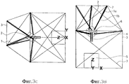
фиг. 3 (а) - (d) изображают шестистержневой обрабатывающий центр, выполненный в виде станочной системы, имеющей треугольное основание, в трехмерной проекции (а), на виде сверху (b), на виде сбоку (с) и на виде спереди (d),
фиг. 4 (а) - (d) изображают шестистержневой обрабатывающий центр, выполненный в виде станочной системы, имеющей прямоугольное основание, в трехмерной проекции (а), на виде сверху (b), на виде сбоку (с) и на виде спереди (d),
фиг. 5 (а) - (d) изображают каркасную конструкцию рамы станочной системы, представленной на фиг. 3, в трехмерной проекции (а), на виде сверху (b), на виде сбоку (с) и на виде спереди (d),
фиг. 6 (а) - (d) изображают станочную систему, показанную на фиг. 3 и имеющую по существу цилиндрическую рабочую планшайбу, в трехмерной проекции (а), на виде сверху (b), на виде сбоку (с) и на виде спереди (d),
фиг. 7 (а) - (d) изображают станочную систему, показанную на фиг. 4 и имеющую по существу цилиндрическую рабочую планшайбу, в трехмерной проекции (а), на виде сверху (b), на виде сбоку (с) и на виде спереди (d).Below the present invention is described on the basis of embodiments and with reference to the drawings, in which:
FIG. 1 (a) - (d) are a schematic representation of a first embodiment of a working faceplate support in a six-rod machining center in a three-dimensional projection (a), in a bottom view (b), in a front view (c) and in a side view (d),
FIG. 2 (a) - (d) are a schematic representation of a second embodiment of the suspension of the working plate in a six-rod machining center in a three-dimensional projection (a), in a bottom view (b), in a front view (c) and in a side view (d),
FIG. 3 (a) - (d) depict a six-core machining center made in the form of a machine system having a triangular base, in a three-dimensional projection (a), in a plan view (b), in a side view (c) and in a front view (d) ,
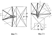
FIG. 4 (a) - (d) depict a six-core machining center made in the form of a machine system having a rectangular base, in a three-dimensional projection (a), in a top view (b), in a side view (c) and in a front view (d) ,
FIG. 5 (a) to (d) depict the frame structure of the frame of the machine system of FIG. 3, in a three-dimensional projection (a), in a plan view (b), in a side view (c) and in a front view (d),
FIG. 6 (a) to (d) depict the machine system shown in FIG. 3 and having a substantially cylindrical working faceplate, in a three-dimensional projection (a), in a plan view (b), in a side view (c) and in a front view (d),
FIG. 7 (a) to (d) depict the machine system shown in FIG. 4 and having a substantially cylindrical working faceplate, in a three-dimensional projection (a), in a plan view (b), in a side view (c) and in a front view (d).
Ниже со ссылкой на фиг. 1 и 2 описана конфигурация подвешивания суппорта 2 к раме 3, осуществление которой возможно в станочных системах, показанных на фиг. 3 - 7. Below with reference to FIG. 1 and 2, the suspension configuration of the
Суппорт 2, в данных вариантах выполнения выполненный в виде рабочей планшайбы, подвешен к раме 3 шестью связями 1. Отдельные связи состоят из стационарной части и телескопической части и могут быть выполнены в виде гидравлического или пневматического цилиндра или в виде реверсивного шарикового винта и гайки. В представленном варианте выполнения соответствующая телескопическая часть шарнирно закреплена на рабочей планшайбе. Для иллюстрации пространственного положения точек шарнирного крепления рабочая планшайба 2 на фиг. 1 показана в виде куба, который в свою очередь подвешен в кубической раме 3. Однако конкретная конструкция рабочей планшайбы и рамы не ограничена строго геометрическими трехмерными конфигурациями, такими как куб или прямоугольный параллелепипед. Как можно видеть на фиг. 1, три точки шарнирного крепления связей на планшайбе 2 соответственно задают общую плоскость приложения, так что всего заданы две отдельные плоскости приложения. В приведенном случае планшайба 2 шарнирно закреплена в центрах шести граней воображаемого куба. В результате этого на рабочей планшайбе образованы отстоящие друг от друга плоскости шарнирного крепления, каждая из которых образована тремя точками шарнирного крепления. The
Когда ось главного шпинделя расположена под прямым углом к этим двум плоскостям, достигается особенно хорошая ее стабилизация. Центры противоположных граней воображаемого куба посредством связей присоединены к параллельным ребрам воображаемого куба рамы 3. В конкретном варианте выполнения, представленном на фиг. 1, эти ребра являются соседними ребрами воображаемого куба рамы. Вариант выполнения, показанный на фиг. 2, отличается от варианта выполнения, показанного на фиг. 1, лишь тем, что противоположные связи шарнирно закреплены на кубе рамы на его противоположных ребрах. В обоих случаях три соответствующие точки шарнирного крепления на раме задают общую плоскость приложения, так что всего заданы две отдельные плоскости приложения. When the axis of the main spindle is at right angles to these two planes, its stabilization is especially good. The centers of the opposite faces of the imaginary cube are connected by ties to the parallel edges of the imaginary cube of the
На основе указанной компоновки точек шарнирного крепления возможно уменьшение объема расчетных вычислений, требуемых для регулирования перемещения отдельных связей при перемещении рабочей планшайбы, для соответствующих противоположных связей 1. Кроме того, данная компоновка обеспечивает возможность равномерной амортизации сил. Поскольку благодаря данной компоновке точек шарнирного крепления на планшайбе 2 связи 1 создают поддерживающий эффект в направлении главной нагрузки, шестистержневой обрабатывающий центр обладает особо высокой конструктивной жесткостью, что позволяет обеспечить высокую точность обработки, при этом отдельные связи могут иметь более компактные размеры. Based on the indicated arrangement of the hinge points, it is possible to reduce the amount of computational calculations required to regulate the movement of individual bonds when moving the working faceplate for the corresponding opposing
Поскольку пределы возможностей структурного конструирования на основе шарнирного крепления связей на рабочей планшайбе в нескольких плоскостях приложения расширены, можно добиться более компактной конструкции рабочей планшайбы, а также большей подвижности, особенно с вращательными степенями свободы. Индивидуальные конфигурации подвески пар связей на соседних или противоположных ребрах воображаемого куба рамы могут быть также скомбинированы друг с другом. Since the limits of structural design capabilities based on the hinged attachment of ties on the working faceplate in several application planes are expanded, a more compact working faceplate design can be achieved, as well as greater mobility, especially with rotational degrees of freedom. Individual suspension configurations of pairs of bonds on adjacent or opposite edges of an imaginary cube of the frame can also be combined with each other.
Шарнирное крепление связей 1 осуществляется при помощи соединений, таких как шаровые шарнирные соединения или универсальные шарниры. The
На фиг. 3 показан шестистержневой обрабатывающий центр, выполненный в виде станочной системы. Рама 3 выполнена в виде каркасной конструкции и имеет треугольное основание. На раме 3 имеется неподвижный инструментальный стол 5. В представленном варианте выполнения на планшайбе 2 имеется главный шпиндель 4, который расположен над столом 5 и который при нахождении планшайбы 2 в исходном положении ориентирован в вертикальном направлении, то есть параллельно оси Z координатной системы обрабатывающего центра. Главный шпиндель проходит в направлении диагонали воображаемого куба рабочей, планшайбы. На основе соответствующей адаптации рамы главный шпиндель может быть ориентирован в пространстве в любом направлении без изменения поддерживающей геометрии планшайбы 2. In FIG. 3 shows a six-core machining center made in the form of a machine tool system.
Как видно на фиг. 4, вместо треугольного основания каркасной конструкции возможно также применение четырехугольного основания. Отдельные точки шарнирного крепления рамы 3 также присоединены к основанию через каркасную конструкцию. В принципе, части рамы также могут быть выполнены обычным образом в виде корпуса. Каркасная конструкция, однако, обладает преимуществом, заключающимся в оптимальном доступе к столу 5 и к пространству, где осуществляется обработка, расположенному внутри каркасной конструкции. As seen in FIG. 4, instead of the triangular base of the frame structure, it is also possible to use a quadrangular base. The individual pivot points of the
На фиг. 5 представлено изображение, где показана только каркасная конструкция для станочной системы, имеющей треугольное основание. In FIG. 5 is an image showing only a frame structure for a machine tool system having a triangular base.
На фиг. 6 и 7 показаны особые варианты выполнения станочных систем, показанных в более общем виде на фиг. 3 и 4, причем эти варианты выполнения в особенности касаются конструкции планшайбы 2. На фиг. 6 и 7 планшайба 2 выполнена в основном в виде цилиндрического тела, в котором вдоль его продольной оси расположен главный шпиндель 4, ориентированный параллельно оси Z координатной системы обрабатывающего центра при нахождении планшайбы 2 в исходном положении. Связи 1 в данном случае шарнирно закреплены на цилиндрической рабочей планшайбе 2 в двух параллельных плоскостях, из которых одна расположена поверх другой и которые на чертеже четко отделены друг от друга, причем ось главного шпинделя 4 проходит под прямым углом к этим плоскостям. Точки шарнирного крепления связей в плоскости, образующей верхнюю плоскость на чертеже, расположены, в свою очередь, в общей верхней плоскости на раме 3, в то время как рамные точки шарнирного крепления связей в нижней плоскости расположены, в свою очередь, в другой соответствующей общей плоскости на раме 3. Наклон верхних связей относительно плоскости, перпендикулярной оси главного шпинделя, противоположен наклону нижних связей в центральном положении покоя планшайбы 2. Для амортизации осевых усилий в направлении оси главного шпинделя верхние связи проходят под более крутым углом, чем нижние связи, которые главным образом служат в качестве радиальных опор по отношению к оси главного шпинделя. Чем меньше крутизна поперечных средств опоры, тем в большей степени планшайба 2 может быть повернута вокруг горизонтальной оси на фиг. 6 и 7. При перемещении планшайбы 2 в направлении стола 5 сохраняется более крутой наклон верхних связей по сравнению с нижними связями. Если за начало принять соответствующую точку соединения на суппорте 2, то угол наклона нижних связей по отношению к плоскости XY предпочтительно отрицательный или же в большинстве случаев равен нулю. In FIG. 6 and 7 show particular embodiments of the machine systems shown more generally in FIG. 3 and 4, wherein these embodiments particularly relate to the design of the
Claims (14)
Applications Claiming Priority (2)
| Application Number | Priority Date | Filing Date | Title |
|---|---|---|---|
| DE19636100.1 | 1996-09-05 | ||
| DE19636100A DE19636100A1 (en) | 1996-09-05 | 1996-09-05 | Hexapod machining center |
Publications (2)
| Publication Number | Publication Date |
|---|---|
| RU2160657C2 true RU2160657C2 (en) | 2000-12-20 |
| RU99104285A RU99104285A (en) | 2001-05-27 |
Family
ID=7804743
Family Applications (1)
| Application Number | Title | Priority Date | Filing Date |
|---|---|---|---|
| RU99104285/02A RU2160657C2 (en) | 1996-09-05 | 1997-07-18 | Six-stem machining center |
Country Status (8)
| Country | Link |
|---|---|
| US (1) | US6155758A (en) |
| EP (1) | EP0925145B1 (en) |
| JP (1) | JP3357075B2 (en) |
| AT (1) | ATE197687T1 (en) |
| DE (2) | DE19636100A1 (en) |
| ES (1) | ES2152689T3 (en) |
| RU (1) | RU2160657C2 (en) |
| WO (1) | WO1998009769A1 (en) |
Cited By (1)
| Publication number | Priority date | Publication date | Assignee | Title |
|---|---|---|---|---|
| RU2561551C2 (en) * | 2010-04-08 | 2015-08-27 | Биа | Hexapod platform and power cylinder, that can be used in hexapod platform |
Families Citing this family (21)
| Publication number | Priority date | Publication date | Assignee | Title |
|---|---|---|---|---|
| DE19806832A1 (en) * | 1998-02-18 | 1999-08-26 | Fraunhofer Ges Forschung | Electrical linear actuator with cased carrier for use in e.g. framed hexapod machine tools offering six degrees of freedom |
| DE29803454U1 (en) * | 1998-02-27 | 1999-06-24 | Fraunhofer Ges Forschung | Hexapod machining center |
| DE19844791C1 (en) * | 1998-09-30 | 2000-05-25 | Hueller Hille Gmbh | Machine tool for multi-axis, especially 5-axis machining of workpieces |
| DE19903613C1 (en) * | 1999-01-29 | 2000-12-07 | Fraunhofer Ges Forschung | Tripod bearing device and method for torsion compensation |
| US6487454B1 (en) * | 1999-03-01 | 2002-11-26 | Adrian Tymes | Programmable-shape array |
| DE19944569C1 (en) * | 1999-09-16 | 2001-05-17 | Variomatic Gmbh & Co Kg | Hexapod-form machining center, in which machine mounting forming working cavity has rectangular base surface and upper rectangular frame of horizontal bearers |
| DE19944568C2 (en) | 1999-09-16 | 2003-05-22 | Variomatic Gmbh & Co Kg | Process for machining spoke rims for vehicles |
| FR2817784B1 (en) * | 2000-12-08 | 2003-04-18 | Renault Automation Comau | MACHINE-TOOL INCLUDING PARALLEL ARCHITECTURE ADOPTING ARTICULATIONS WITH DEFORMATION AND ARTICULATION WITH ADAPTED DEFORMATION |
| US6741912B2 (en) * | 2001-07-02 | 2004-05-25 | Microbotic A/S | Flexible tool for handling small objects |
| AT411445B (en) * | 2001-09-03 | 2004-01-26 | Krauseco Werkzeugmaschinen Gmb | MACHINE TOOL |
| DE10156491B4 (en) * | 2001-11-16 | 2005-10-20 | Fraunhofer Ges Forschung | Device for supporting a carrier |
| DE10156871A1 (en) * | 2001-12-20 | 2003-07-10 | Univ Ilmenau Tech | Assembly to set the position of a platform, in relation to a frame, has struts of variable length linked to the platform/frame by universal joints, with a rotary drive transmitted to the struts to set their length |
| ITTO20030502A1 (en) * | 2003-07-01 | 2005-01-02 | O M V Ohg Venete S R L | NUMERICAL CONTROL MACHINE. |
| US7411772B1 (en) | 2005-01-07 | 2008-08-12 | Adrian Jeremy Tymes | Casimir effect conversion |
| US8066548B1 (en) | 2006-10-19 | 2011-11-29 | Max-Tek, LLC | Multi-axes contouring machine and method of use |
| FR2966534B1 (en) * | 2010-10-22 | 2012-12-21 | Thales Sa | FLEXIBLE COMPACT CARDAN AND SPACE ENGINE COMPRISING SUCH A CARDAN. |
| DE102012002400B4 (en) * | 2011-03-17 | 2020-06-18 | Eb-Invent Gmbh | manipulator |
| GB2495958A (en) * | 2011-10-26 | 2013-05-01 | Core Pd Ltd | Tension cable robot |
| CN103831818B (en) * | 2014-02-26 | 2016-01-20 | 南京航空航天大学 | The cube linkage that linear drives implementation space Three Degree Of Freedom class ball-joint rotates |
| CN106737571B (en) * | 2016-11-15 | 2019-02-12 | 常州大学 | A kind of multidimensional vibration reduction tensioning entirety parallel institution |
| CN111692466B (en) * | 2020-05-09 | 2021-11-02 | 广州大学 | Cloud platform device and camera equipment |
Family Cites Families (8)
| Publication number | Priority date | Publication date | Assignee | Title |
|---|---|---|---|---|
| US5028180A (en) * | 1989-09-01 | 1991-07-02 | Sheldon Paul C | Six-axis machine tool |
| US5401128A (en) * | 1991-08-26 | 1995-03-28 | Ingersoll Milling Machine Company | Octahedral machine with a hexapodal triangular servostrut section |
| FR2688437B1 (en) * | 1992-03-11 | 1994-06-10 | Centre Nat Rech Scient | PARALLEL SPATIAL MANIPULATOR WITH SIX DEGREES OF FREEDOM. |
| SE500598C2 (en) * | 1992-12-17 | 1994-07-25 | Berol Nobel Ab | Use of a secondary amine as a corrosion inhibiting and antimicrobial agent and an aqueous alkaline liquid for industrial purposes containing said amine |
| EP0674969B1 (en) * | 1994-03-02 | 2010-02-17 | Renishaw plc | Coordinate positioning machine |
| US5787758A (en) * | 1996-09-03 | 1998-08-04 | Sheldon/Van Someren, Inc. | Three-axis machine for rapid and rigid manipulation of components |
| US5832783A (en) * | 1996-10-22 | 1998-11-10 | Sheldon/Van Someren Inc. | Three-axis machine structure |
| US5906461A (en) * | 1997-04-09 | 1999-05-25 | Ina Walzlager Schaeffler Ohg | Machine tool with adjustable strut assembly |
-
1996
- 1996-09-05 DE DE19636100A patent/DE19636100A1/en not_active Withdrawn
-
1997
- 1997-07-18 ES ES97932838T patent/ES2152689T3/en not_active Expired - Lifetime
- 1997-07-18 JP JP51215198A patent/JP3357075B2/en not_active Expired - Fee Related
- 1997-07-18 DE DE59702668T patent/DE59702668D1/en not_active Expired - Lifetime
- 1997-07-18 WO PCT/EP1997/003861 patent/WO1998009769A1/en active IP Right Grant
- 1997-07-18 AT AT97932838T patent/ATE197687T1/en not_active IP Right Cessation
- 1997-07-18 EP EP97932838A patent/EP0925145B1/en not_active Expired - Lifetime
- 1997-07-18 RU RU99104285/02A patent/RU2160657C2/en not_active IP Right Cessation
-
1999
- 1999-03-03 US US09/261,523 patent/US6155758A/en not_active Expired - Fee Related
Cited By (1)
| Publication number | Priority date | Publication date | Assignee | Title |
|---|---|---|---|---|
| RU2561551C2 (en) * | 2010-04-08 | 2015-08-27 | Биа | Hexapod platform and power cylinder, that can be used in hexapod platform |
Also Published As
| Publication number | Publication date |
|---|---|
| JP3357075B2 (en) | 2002-12-16 |
| WO1998009769A1 (en) | 1998-03-12 |
| EP0925145B1 (en) | 2000-11-22 |
| DE19636100A1 (en) | 1998-03-12 |
| JP2000505006A (en) | 2000-04-25 |
| ES2152689T3 (en) | 2001-02-01 |
| ATE197687T1 (en) | 2000-12-15 |
| EP0925145A1 (en) | 1999-06-30 |
| US6155758A (en) | 2000-12-05 |
| DE59702668D1 (en) | 2000-12-28 |
Similar Documents
| Publication | Publication Date | Title |
|---|---|---|
| RU2160657C2 (en) | Six-stem machining center | |
| US5259710A (en) | Octahedral machine tool frame | |
| CN101346208B (en) | Scanning head and processor with the same | |
| US6682278B2 (en) | Universal combined milling and boring machine | |
| JP5303455B2 (en) | Coordinate positioning machine | |
| JP4008814B2 (en) | Platform linear motion positioning device | |
| JP2004512476A (en) | Improvements in parallel link machine design | |
| RU99104285A (en) | HEXISTER PROCESSING CENTER | |
| EP0674969B1 (en) | Coordinate positioning machine | |
| US6241437B1 (en) | Hexapodal machining center | |
| JP4484698B2 (en) | Apparatus for placing optical components in a structure | |
| EP1424507B1 (en) | Elementary and complex coupling devices, and their use | |
| JP2000126956A (en) | Parallel mechanism machine tool | |
| JPS6374540A (en) | Fixture | |
| JP2004314189A (en) | Positioning device using parallel mechanism | |
| JP6093812B2 (en) | Machine Tools | |
| KR102231528B1 (en) | Seismic isolation device | |
| CN214608130U (en) | Light adjustable suspension machine frame | |
| CN114367961B (en) | Novel five-degree-of-freedom parallel mechanism capable of realizing three-dimensional translation and two-dimensional rotation | |
| GB2387800A (en) | High precision machine tool structure | |
| JPH04502430A (en) | Mechanical equipment and structure | |
| SU810394A1 (en) | Diamond boring machine | |
| TWI628031B (en) | Supporting device | |
| JP2023097963A (en) | Seat support mechanism for four-wheeled vehicle driving simulator | |
| JPH09131686A (en) | Parallel link manipulator |
Legal Events
| Date | Code | Title | Description |
|---|---|---|---|
| MM4A | The patent is invalid due to non-payment of fees |
Effective date: 20080719 |