RU2160367C2 - Gas turbine blade fastening device - Google Patents
Gas turbine blade fastening device Download PDFInfo
- Publication number
- RU2160367C2 RU2160367C2 RU97112384/06A RU97112384A RU2160367C2 RU 2160367 C2 RU2160367 C2 RU 2160367C2 RU 97112384/06 A RU97112384/06 A RU 97112384/06A RU 97112384 A RU97112384 A RU 97112384A RU 2160367 C2 RU2160367 C2 RU 2160367C2
- Authority
- RU
- Russia
- Prior art keywords
- disk
- blades
- fixing plate
- blade
- gas turbine
- Prior art date
Links
Images

Classifications
-
- F—MECHANICAL ENGINEERING; LIGHTING; HEATING; WEAPONS; BLASTING
- F01—MACHINES OR ENGINES IN GENERAL; ENGINE PLANTS IN GENERAL; STEAM ENGINES
- F01D—NON-POSITIVE DISPLACEMENT MACHINES OR ENGINES, e.g. STEAM TURBINES
- F01D5/00—Blades; Blade-carrying members; Heating, heat-insulating, cooling or antivibration means on the blades or the members
- F01D5/12—Blades
- F01D5/14—Form or construction
- F01D5/20—Specially-shaped blade tips to seal space between tips and stator
-
- F—MECHANICAL ENGINEERING; LIGHTING; HEATING; WEAPONS; BLASTING
- F01—MACHINES OR ENGINES IN GENERAL; ENGINE PLANTS IN GENERAL; STEAM ENGINES
- F01D—NON-POSITIVE DISPLACEMENT MACHINES OR ENGINES, e.g. STEAM TURBINES
- F01D11/00—Preventing or minimising internal leakage of working-fluid, e.g. between stages
- F01D11/005—Sealing means between non relatively rotating elements
- F01D11/006—Sealing the gap between rotor blades or blades and rotor
-
- F—MECHANICAL ENGINEERING; LIGHTING; HEATING; WEAPONS; BLASTING
- F01—MACHINES OR ENGINES IN GENERAL; ENGINE PLANTS IN GENERAL; STEAM ENGINES
- F01D—NON-POSITIVE DISPLACEMENT MACHINES OR ENGINES, e.g. STEAM TURBINES
- F01D5/00—Blades; Blade-carrying members; Heating, heat-insulating, cooling or antivibration means on the blades or the members
- F01D5/12—Blades
- F01D5/22—Blade-to-blade connections, e.g. for damping vibrations
-
- F—MECHANICAL ENGINEERING; LIGHTING; HEATING; WEAPONS; BLASTING
- F01—MACHINES OR ENGINES IN GENERAL; ENGINE PLANTS IN GENERAL; STEAM ENGINES
- F01D—NON-POSITIVE DISPLACEMENT MACHINES OR ENGINES, e.g. STEAM TURBINES
- F01D5/00—Blades; Blade-carrying members; Heating, heat-insulating, cooling or antivibration means on the blades or the members
- F01D5/30—Fixing blades to rotors; Blade roots ; Blade spacers
- F01D5/32—Locking, e.g. by final locking blades or keys
- F01D5/323—Locking of axial insertion type blades by means of a key or the like parallel to the axis of the rotor
-
- Y—GENERAL TAGGING OF NEW TECHNOLOGICAL DEVELOPMENTS; GENERAL TAGGING OF CROSS-SECTIONAL TECHNOLOGIES SPANNING OVER SEVERAL SECTIONS OF THE IPC; TECHNICAL SUBJECTS COVERED BY FORMER USPC CROSS-REFERENCE ART COLLECTIONS [XRACs] AND DIGESTS
- Y10—TECHNICAL SUBJECTS COVERED BY FORMER USPC
- Y10T—TECHNICAL SUBJECTS COVERED BY FORMER US CLASSIFICATION
- Y10T29/00—Metal working
- Y10T29/49—Method of mechanical manufacture
- Y10T29/49316—Impeller making
- Y10T29/4932—Turbomachine making
- Y10T29/49321—Assembling individual fluid flow interacting members, e.g., blades, vanes, buckets, on rotary support member
Landscapes
- Engineering & Computer Science (AREA)
- Mechanical Engineering (AREA)
- General Engineering & Computer Science (AREA)
- Turbine Rotor Nozzle Sealing (AREA)
Abstract
Description
Данное изобретение относится к устройству крепления лопатки на диске газовой турбины и, в частности, к фиксирующей пластине, удерживающей лопатку, демпфирующей ее колебания и уплотняющей соединение лопатки с диском. This invention relates to a device for attaching a blade to a disk of a gas turbine and, in particular, to a fixing plate holding the blade, damping its vibrations and sealing the connection of the blade with the disk.
Уровень техники
Как правило, лопатки газовой турбины крепятся к диску с помощью соединений ласточкиного хвоста, имеющих соединительные элементы, которые выполнены по профилю елочки. Одним из упомянутых соединительных элементов является хвостовик лопатки, выполненный профилем елочки. Точное радиальное положение лопатки определяется точной посадкой по месту обоих елочных профилей элементов соединения. Поэтому проектирование подобных соединений предусматривает условие, чтобы опорные поверхности лопаток располагались в соединительном элементе диска в максимально смещенном к периферии положении лопатки. Соединительный элемент диска, естественно, должен быть выполнен с зазором, чтобы позволить установку соединительного элемента лопатки.State of the art
As a rule, gas turbine blades are attached to the disk by means of swallow tail joints having connecting elements that are made along the herringbone profile. One of the mentioned connecting elements is the shank of the blade, made profile herringbone. The exact radial position of the blade is determined by the exact fit in place of both Christmas-tree profiles of the connection elements. Therefore, the design of such joints provides for the condition that the supporting surfaces of the blades are located in the connecting element of the disk in the maximum position of the blade to the periphery. The connecting element of the disk, of course, must be made with a gap to allow the installation of the connecting element of the blade.
В подобной конструкции для удерживания лопатки на диске от осевых смещений необходимы средства фиксации лопатки. In such a design, means for fixing the blade are needed to hold the blade on the disk from axial displacements.
При высоких оборотах ротора турбины центробежная сила удерживает лопатку в крайнем периферийном положении. Однако, технология сборки рабочего колеса турбины требует, чтобы лопатка оставалась примерно в одном и том же положении как при балансировке ротора со скоростью вращения 1000 об/мин, так и при шлифовании торцов лопаток со скоростью вращения 100 об/мин. At high speeds of the turbine rotor, centrifugal force keeps the blade in the extreme peripheral position. However, the turbine impeller assembly technology requires that the blade remain in approximately the same position both when balancing the rotor at a speed of 1000 rpm and when grinding the ends of the blades at a speed of 100 rpm.
Для противодействия проникновению газа из области проточной части с более высоким давлением газа через зазоры между полками лопаток в полость диска турбины необходимо использовать уплотнение этих зазоров. To prevent the penetration of gas from the area of the flowing part with a higher gas pressure through the gaps between the shelves of the blades into the cavity of the turbine disk, it is necessary to use a seal of these gaps.
Для снижения вибронапряжений, возникающих при вращении ротора турбины в материале лопаток, эффективной мерой является демпфирование колебаний лопаток. To reduce the vibration stresses that occur during rotation of the turbine rotor in the material of the blades, an effective measure is the damping of the vibrations of the blades.
Сущность изобретения
Устройство крепления лопатки газовой турбины содержит диск газовой турбины с пазами соединения типа ласточкиного хвоста, расположенными по окружности периферии этого диска так, что между пазами имеются замковые выступы диска. В каждом из пазов располагаются хвостовики лопаток газовой турбины, каждая из которых имеет паз соединения ласточкиного хвоста. С одной стороны лопатки имеют осевой упор, прилегающий к первой стороне периферийной замковой части диска.SUMMARY OF THE INVENTION
The gas turbine blade attachment device comprises a gas turbine disk with dovetail-type grooves arranged around a circumference of the periphery of the disk so that there are locking protrusions of the disk between the grooves. In each of the grooves are the shanks of the blades of the gas turbine, each of which has a groove connecting the swallow tail. On one side of the blade have an axial stop adjacent to the first side of the peripheral locking part of the disk.
На всех лопатках имеются полки, расположенные по окружности диска. Между диском и расположенными рядом друг с другом полками лопаток имеется зазор, проходящий в осевом направлении. В этом зазоре установлена удлиненная фиксирующая пластина, а язычок этой пластины, выступающий с первой стороны диска, отогнут к периферии до контакта с расположенными рядом друг с другом лопатками газовой турбины, причем этот язычок отгибается после установки фиксирующей пластины. Другой конец фиксирующей пластины перед ее установкой отогнут к центру диска и находится в состоянии упругого контакта с замковым выступом диска. Таким образом, упругий язычок старается сместить диск в осевом направлении, а отогнутый язычок с другой стороны удерживает лопатки газовой турбины от осевого смещения. All blades have shelves located around the circumference of the disc. Between the disk and the adjacent shelves of the blades there is a gap extending in the axial direction. An elongated fixing plate is installed in this gap, and the tongue of this plate, protruding from the first side of the disk, is bent to the periphery until it contacts gas turbine blades adjacent to each other, and this tongue is unbent after installing the fixing plate. The other end of the fixing plate is bent toward the center of the disk before being installed and is in a state of elastic contact with the locking protrusion of the disk. Thus, the elastic tongue tries to shift the disk in the axial direction, and the bent tongue on the other hand keeps the gas turbine blades from axial displacement.
Также фиксирующая пластина имеет радиальный изгиб, благодаря которому фиксирующая пластина в деформированном состоянии отжимает лопатки от диска в радиальном направлении. Also, the locking plate has a radial bend, due to which the locking plate in a deformed state pushes the blades from the disk in the radial direction.
Перечень фигур чертежей
Фиг. 1 - вид фрагмента рабочего колеса турбины снаружи турбины, демонстрирующий лопатки и их полки.List of drawings
FIG. 1 is a view of a fragment of a turbine impeller outside a turbine, showing blades and their shelves.
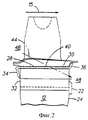
Фиг. 2 - разрез 2 - 2, показанный на фиг. 1. FIG. 2 is a section 2 - 2 shown in FIG. 1.
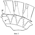
Фиг. 3 - фронтальный вид фрагмента, показанного на фиг. 2, со стороны сопла двигателя. FIG. 3 is a front view of the fragment shown in FIG. 2, from the nozzle side of the engine.
Фиг. 4 - фронтальный вид фрагмента, показанного на фиг. 2, со стороны камеры сгорания. FIG. 4 is a front view of the fragment shown in FIG. 2, from the side of the combustion chamber.
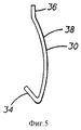
Фиг. 5 - вид сбоку фиксирующей пластины перед установкой. FIG. 5 is a side view of the fixing plate before installation.
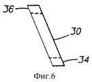
Фиг. 6 - вид сверху фиксирующей пластины перед установкой. FIG. 6 is a plan view of a fixing plate before installation.
Сведения, подтверждающие возможность осуществления изобретения
Как показано на фиг. 1, устройство 10 крепления лопатки газовой турбины включает в себя диск 12 турбины и несколько лопаток 14, находящихся в потоке газа 15. На фиг. 2, 3 и 4 также видно, что по окружности диска выполнено несколько пазов соединения ласточкиного хвоста 16. Между этими пазами расположены замковые выступы 18 диска. Каждая лопатка газовой турбины имеет хвостовик 20, форма которого идентична форме пазов соединения ласточкиного хвоста 16. Каждый хвостовик находится в одном из таких пазов диска. С одной стороны каждая лопатка имеет осевой упор 22, упирающийся в первую сторону 24 диска. Лопатки вставляются в пазы с этой первой стороны диска и вводятся в них до соприкосновения осевого упора 22 с первой стороной диска.Information confirming the possibility of carrying out the invention
As shown in FIG. 1, the gas turbine blade attachment device 10 includes a
Все лопатки имеют полки 26, примыкающие друг к другу по окружности диска. Между диском и полками лопаток имеется зазор 28, проходящий в осевом направлении. All blades have
В этом зазоре находится удлиненная фиксирующая пластина 30. Она вводится в этот зазор со второй стороны 32 диска. Фиксирующая пластина изготавливается с упругим язычком 34 на одном конце. Пластину вводят в зазор до упругого контакта язычка с поверхностью 32. Затем, для поджатия язычка к пластине прикладывают дополнительное усилие. Далее, не снимая поджимающего усилия, с первой стороны диска отгибают язычок 36 к периферии до контакта с расположенными рядом лопатками турбины. После отпускания упругого язычка 34, он продолжает находиться в упруго-деформированном состоянии, оказывая тем самым постоянное поджимающее действие на лопатки газовой турбины, противодействующее силе, приложенной к упору 22. При этом с диском соприкасается только кромка 35 язычка 34. In this gap there is an
Фиг. 5 и 6 показывают конфигурацию фиксирующей пластины 30 перед установкой в замок. Язычок 34, который предназначен для упругого контакта с поверхностью диска, отогнут предварительно. Также следует обратить внимание на изгиб 38 пластины. На фиг. 2 видно, что при распрямлении этого изгиба пластина поджимает лопатки к периферии, в положение 40. Благодаря этому поджатию лопатки постоянно находятся в крайнем периферийном положении как при шлифовании торцов лопаток со скоростью вращения примерно 100 об/мин, так и при балансировке ротора газовой турбины со скоростью вращения около 1000 об/мин. FIG. 5 and 6 show the configuration of the
Это радиальное поджатие в сочетании с осевым поджатием фиксирующей пластины демпфирует колебания лопаток. Кроме того, фиксирующая пластина препятствует проходу газа через зазор 42. При отсутствии фиксирующих пластин поток газа, обозначенный на фиг. 2 стрелкой 44, проходил бы из области 46 проточной части, расположенной относительно рабочего колеса турбины выше по потоку газа через зазоры 42, в область 48 под лопатками, расположенную относительно рабочего колеса турбины ниже по потоку газа. This radial preload in combination with the axial preload of the retaining plate dampens the vibrations of the blades. In addition, the fixing plate prevents the passage of gas through the
На фиг. 6 представлен вид сверху фиксирующей пластины 30 с неотогнутым язычком 36. In FIG. 6 is a plan view of a
Предложенное в изобретении устройство обеспечивает фиксацию лопаток на диске газовой турбины и уплотняет соединение лопатки с диском. Также это устройство выполняет функции демпфера колебаний лопаток и создает радиальное усилие, поджимающее лопатки к периферии, что упрощает балансировку ротора газовой турбины и шлифование торцов лопаток. The device proposed in the invention provides fixation of the blades on the gas turbine disk and seals the connection of the blade with the disk. Also, this device performs the functions of a vibration damper for the blades and creates a radial force, pressing the blades to the periphery, which simplifies the balancing of the gas turbine rotor and grinding the ends of the blades.
Claims (3)
Applications Claiming Priority (2)
| Application Number | Priority Date | Filing Date | Title |
|---|---|---|---|
| US08/356,094 US5518369A (en) | 1994-12-15 | 1994-12-15 | Gas turbine blade retention |
| US08/356,094 | 1994-12-15 |
Publications (2)
| Publication Number | Publication Date |
|---|---|
| RU97112384A RU97112384A (en) | 1999-06-10 |
| RU2160367C2 true RU2160367C2 (en) | 2000-12-10 |
Family
ID=23400109
Family Applications (1)
| Application Number | Title | Priority Date | Filing Date |
|---|---|---|---|
| RU97112384/06A RU2160367C2 (en) | 1994-12-15 | 1995-12-07 | Gas turbine blade fastening device |
Country Status (8)
| Country | Link |
|---|---|
| US (1) | US5518369A (en) |
| EP (1) | EP0797724B1 (en) |
| JP (1) | JP3751636B2 (en) |
| CZ (1) | CZ288815B6 (en) |
| DE (1) | DE69515508T2 (en) |
| PL (1) | PL178887B1 (en) |
| RU (1) | RU2160367C2 (en) |
| WO (1) | WO1996018803A1 (en) |
Cited By (7)
| Publication number | Priority date | Publication date | Assignee | Title |
|---|---|---|---|---|
| RU2461717C1 (en) * | 2011-03-17 | 2012-09-20 | Федеральное государственное унитарное предприятие "Центральный институт авиационного моторостроения имени П.И. Баранова" | Vibration damping device of wide-chord moving blades of fans with high conicity of sleeve, and gas turbine engine fan |
| RU2479724C2 (en) * | 2007-06-26 | 2013-04-20 | Снекма | Fan rotor and turbomachine containing such rotor |
| RU2493370C2 (en) * | 2007-04-27 | 2013-09-20 | Снекма | Shock absorber for blades of gas-turbine engine, rotor of gas-turbine engine (versions), compressor of gas-turbine engine (versions), and gas-turbine engine (versions) |
| RU2557826C2 (en) * | 2010-12-09 | 2015-07-27 | Альстом Текнолоджи Лтд | Gas turbine with axial hot air flow, and axial compressor |
| RU2602643C1 (en) * | 2015-06-18 | 2016-11-20 | федеральное государственное бюджетное образовательное учреждение высшего образования "Пермский национальный исследовательский политехнический университет" | Turbine machine impeller with blades damper |
| RU2662755C2 (en) * | 2016-11-29 | 2018-07-30 | федеральное государственное автономное образовательное учреждение высшего образования "Самарский национальный исследовательский университет имени академика С.П. Королёва" | Place of mounting of working blades of booster rotors and compressor of aviation engines of fifth generation; booster rotor and rotor of high pressure compressor of first generation aviation engine, with working blades, fixed with help of swallowtail type locks in ring grooves of these devices; method of assembling place of mounting working blades of booster rotors and compressor |
| RU2686353C2 (en) * | 2017-06-27 | 2019-04-25 | федеральное государственное автономное образовательное учреждение высшего образования "Самарский национальный исследовательский университет имени академика С.П. Королёва" | Place of mounting of working blades and low and high pressure compressor of aviation engines of fifth generation, rotor of low pressure compressor and rotor of high pressure compressor of fifth generation aviation engine, with working blades, fixed with help of dovetail type locks in ring grooves of these devices, method of assembling place of mounting working blades of rotors and compressor |
Families Citing this family (22)
| Publication number | Priority date | Publication date | Assignee | Title |
|---|---|---|---|---|
| US6109877A (en) * | 1998-11-23 | 2000-08-29 | Pratt & Whitney Canada Corp. | Turbine blade-to-disk retention device |
| US6837686B2 (en) | 2002-09-27 | 2005-01-04 | Pratt & Whitney Canada Corp. | Blade retention scheme using a retention tab |
| DE102005024932A1 (en) | 2005-05-31 | 2006-12-07 | Rolls-Royce Deutschland Ltd & Co Kg | Turbinenschaufelaxialsperre |
| EP1916389A1 (en) | 2006-10-26 | 2008-04-30 | Siemens Aktiengesellschaft | Turbine blade assembly |
| US7806662B2 (en) * | 2007-04-12 | 2010-10-05 | Pratt & Whitney Canada Corp. | Blade retention system for use in a gas turbine engine |
| FR2918106B1 (en) | 2007-06-27 | 2011-05-06 | Snecma | AXIS RETAINING DEVICE OF AUBES MOUNTED ON A TURBOMACHINE ROTOR DISC. |
| US8485785B2 (en) * | 2007-07-19 | 2013-07-16 | Siemens Energy, Inc. | Wear prevention spring for turbine blade |
| US20090060746A1 (en) * | 2007-08-30 | 2009-03-05 | Honeywell International, Inc. | Blade retaining clip |
| MX2010004477A (en) * | 2007-10-25 | 2010-05-03 | Siemens Ag | Turbine blade assembly and seal strip. |
| EP2088287A1 (en) * | 2008-02-08 | 2009-08-12 | Siemens Aktiengesellschaft | Assembly for axial protection on rotor blades in a rotor of a gas turbine |
| US8221083B2 (en) * | 2008-04-15 | 2012-07-17 | United Technologies Corporation | Asymmetrical rotor blade fir-tree attachment |
| US9174292B2 (en) * | 2008-04-16 | 2015-11-03 | United Technologies Corporation | Electro chemical grinding (ECG) quill and method to manufacture a rotor blade retention slot |
| DE102009011879A1 (en) * | 2009-03-05 | 2010-09-16 | Mtu Aero Engines Gmbh | Integrally bladed rotor and method of making an integrally bladed rotor |
| US20110106284A1 (en) * | 2009-11-02 | 2011-05-05 | Mold-Masters (2007) Limited | System for use in performance of injection molding operations |
| US8562301B2 (en) | 2010-04-20 | 2013-10-22 | Hamilton Sundstrand Corporation | Turbine blade retention device |
| US8727733B2 (en) | 2011-05-26 | 2014-05-20 | General Electric Company | Gas turbine compressor last stage rotor blades with axial retention |
| US8894378B2 (en) * | 2011-07-26 | 2014-11-25 | General Electric Company | Systems, methods, and apparatus for sealing a bucket dovetail in a turbine |
| US8894372B2 (en) | 2011-12-21 | 2014-11-25 | General Electric Company | Turbine rotor insert and related method of installation |
| WO2015038605A1 (en) | 2013-09-12 | 2015-03-19 | United Technologies Corporation | Disk outer rim seal |
| US10145382B2 (en) | 2015-12-30 | 2018-12-04 | General Electric Company | Method and system for separable blade platform retention clip |
| US9845690B1 (en) * | 2016-06-03 | 2017-12-19 | General Electric Company | System and method for sealing flow path components with front-loaded seal |
| US11208903B1 (en) * | 2020-11-20 | 2021-12-28 | Solar Turbines Incorporated | Stiffness coupling and vibration damping for turbine blade shroud |
Family Cites Families (16)
| Publication number | Priority date | Publication date | Assignee | Title |
|---|---|---|---|---|
| GB671960A (en) * | 1949-08-23 | 1952-05-14 | Bristol Aeroplane Co Ltd | Improvements in or relating to attachment means for rotor blades |
| US2761648A (en) * | 1951-09-18 | 1956-09-04 | A V Roe Canada Ltd | Rotor blade locking device |
| US2847187A (en) * | 1955-01-21 | 1958-08-12 | United Aircraft Corp | Blade locking means |
| US2942842A (en) * | 1956-06-13 | 1960-06-28 | Gen Motors Corp | Turbine blade lock |
| DE1032753B (en) * | 1956-10-05 | 1958-06-26 | Maschf Augsburg Nuernberg Ag | Locking of rotor blades of flow machines held in a form-fitting manner in axial grooves of a rotor disk |
| DE1051286B (en) * | 1958-06-02 | 1959-02-26 | Her Majesty The Queen In The R | Fuse for a blade held in an axial groove of a centrifugal machine |
| GB925273A (en) * | 1960-10-15 | 1963-05-01 | Daimler Benz Ag | Improvements relating to rotors for turbines or compressors |
| US3202398A (en) * | 1962-11-05 | 1965-08-24 | James E Webb | Locking device for turbine rotor blades |
| US3248081A (en) * | 1964-12-29 | 1966-04-26 | Gen Electric | Axial locating means for airfoils |
| US3598503A (en) * | 1969-09-19 | 1971-08-10 | United Aircraft Corp | Blade lock |
| US4029436A (en) * | 1975-06-17 | 1977-06-14 | United Technologies Corporation | Blade root feather seal |
| FR2503247B1 (en) * | 1981-04-07 | 1985-06-14 | Snecma | IMPROVEMENTS ON THE FLOORS OF A GAS TURBINE OF TURBOREACTORS PROVIDED WITH AIR COOLING MEANS OF THE TURBINE WHEEL DISC |
| US4483661A (en) * | 1983-05-02 | 1984-11-20 | General Electric Company | Blade assembly for a turbomachine |
| FR2603333B1 (en) * | 1986-09-03 | 1990-07-20 | Snecma | TURBOMACHINE ROTOR COMPRISING A MEANS OF AXIAL LOCKING AND SEALING OF BLADES MOUNTED IN AXIAL PINS OF THE DISC AND MOUNTING METHOD |
| US4872810A (en) * | 1988-12-14 | 1989-10-10 | United Technologies Corporation | Turbine rotor retention system |
| US5281097A (en) * | 1992-11-20 | 1994-01-25 | General Electric Company | Thermal control damper for turbine rotors |
-
1994
- 1994-12-15 US US08/356,094 patent/US5518369A/en not_active Expired - Lifetime
-
1995
- 1995-12-07 RU RU97112384/06A patent/RU2160367C2/en not_active IP Right Cessation
- 1995-12-07 EP EP95938335A patent/EP0797724B1/en not_active Expired - Lifetime
- 1995-12-07 JP JP51798096A patent/JP3751636B2/en not_active Expired - Fee Related
- 1995-12-07 DE DE69515508T patent/DE69515508T2/en not_active Expired - Fee Related
- 1995-12-07 CZ CZ19971782A patent/CZ288815B6/en not_active IP Right Cessation
- 1995-12-07 PL PL95320693A patent/PL178887B1/en not_active IP Right Cessation
- 1995-12-07 WO PCT/CA1995/000683 patent/WO1996018803A1/en active IP Right Grant
Non-Patent Citations (1)
| Title |
|---|
| СКУБАЧЕВСКИЙ Г.С. Авиационные газотурбинные двигатели - М.: Машиностроение, 1965, с.100 - 101, рис.5.10. * |
Cited By (8)
| Publication number | Priority date | Publication date | Assignee | Title |
|---|---|---|---|---|
| RU2493370C2 (en) * | 2007-04-27 | 2013-09-20 | Снекма | Shock absorber for blades of gas-turbine engine, rotor of gas-turbine engine (versions), compressor of gas-turbine engine (versions), and gas-turbine engine (versions) |
| RU2479724C2 (en) * | 2007-06-26 | 2013-04-20 | Снекма | Fan rotor and turbomachine containing such rotor |
| RU2557826C2 (en) * | 2010-12-09 | 2015-07-27 | Альстом Текнолоджи Лтд | Gas turbine with axial hot air flow, and axial compressor |
| US9551235B2 (en) | 2010-12-09 | 2017-01-24 | General Electric Company | Axial-flow machine |
| RU2461717C1 (en) * | 2011-03-17 | 2012-09-20 | Федеральное государственное унитарное предприятие "Центральный институт авиационного моторостроения имени П.И. Баранова" | Vibration damping device of wide-chord moving blades of fans with high conicity of sleeve, and gas turbine engine fan |
| RU2602643C1 (en) * | 2015-06-18 | 2016-11-20 | федеральное государственное бюджетное образовательное учреждение высшего образования "Пермский национальный исследовательский политехнический университет" | Turbine machine impeller with blades damper |
| RU2662755C2 (en) * | 2016-11-29 | 2018-07-30 | федеральное государственное автономное образовательное учреждение высшего образования "Самарский национальный исследовательский университет имени академика С.П. Королёва" | Place of mounting of working blades of booster rotors and compressor of aviation engines of fifth generation; booster rotor and rotor of high pressure compressor of first generation aviation engine, with working blades, fixed with help of swallowtail type locks in ring grooves of these devices; method of assembling place of mounting working blades of booster rotors and compressor |
| RU2686353C2 (en) * | 2017-06-27 | 2019-04-25 | федеральное государственное автономное образовательное учреждение высшего образования "Самарский национальный исследовательский университет имени академика С.П. Королёва" | Place of mounting of working blades and low and high pressure compressor of aviation engines of fifth generation, rotor of low pressure compressor and rotor of high pressure compressor of fifth generation aviation engine, with working blades, fixed with help of dovetail type locks in ring grooves of these devices, method of assembling place of mounting working blades of rotors and compressor |
Also Published As
| Publication number | Publication date |
|---|---|
| EP0797724A1 (en) | 1997-10-01 |
| JP3751636B2 (en) | 2006-03-01 |
| CZ288815B6 (en) | 2001-09-12 |
| EP0797724B1 (en) | 2000-03-08 |
| DE69515508D1 (en) | 2000-04-13 |
| PL178887B1 (en) | 2000-06-30 |
| DE69515508T2 (en) | 2000-09-14 |
| WO1996018803A1 (en) | 1996-06-20 |
| CZ178297A3 (en) | 1997-09-17 |
| PL320693A1 (en) | 1997-10-27 |
| US5518369A (en) | 1996-05-21 |
| JPH10510344A (en) | 1998-10-06 |
Similar Documents
| Publication | Publication Date | Title |
|---|---|---|
| RU2160367C2 (en) | Gas turbine blade fastening device | |
| EP0717169B1 (en) | Turbine engine rotor blade platform sealing and vibration damping device | |
| RU2438019C2 (en) | Unit of turbine blade | |
| JP4049865B2 (en) | Turbine blade integrated damper seal | |
| US4192633A (en) | Counterweighted blade damper | |
| EP1291492B1 (en) | Turbine blade damper and seal assembly | |
| RU2518749C2 (en) | Turbomachine rotor section | |
| RU2516992C2 (en) | Turbo machine (versions) | |
| US6851932B2 (en) | Vibration damper assembly for the buckets of a turbine | |
| RU2289699C2 (en) | Intermediate segment for holding stator ring of high-pressure turbine in turbomachine made for adjusting of clearances | |
| KR100577546B1 (en) | Turbine bucket cover and brush seal | |
| US7182577B2 (en) | Turbine rotor blade and turbine | |
| CA1284954C (en) | Interblade seal for turbomachine rotor | |
| JP4942844B2 (en) | Axial fixing structure of rotor blade in rotor and gas turbine provided with the axial fixing structure | |
| RU97112384A (en) | GAS TURBINE SHOULDER MOUNTING DEVICE | |
| US5622476A (en) | Axial fixing arrangement for rotor blades of a turbomachine | |
| JPS63167104A (en) | Device for clamping member | |
| JPS61155602A (en) | Seal of blade root | |
| EP0774049B1 (en) | Rotor blade with platform support and damper positioning means | |
| EP1607579B1 (en) | Locking means for gas turbine engines | |
| JP3351078B2 (en) | Turbocharger | |
| JPS58174105A (en) | Vibration damper for stator blade row of axial-flow turbo-machine | |
| KR100837134B1 (en) | Securing system for the rotor blades of axial flow turbo engines | |
| JP2000220405A (en) | Turbine rotor blade | |
| CN112534119B (en) | Rotor with a rotor component arranged between two rotor disks |
Legal Events
| Date | Code | Title | Description |
|---|---|---|---|
| MM4A | The patent is invalid due to non-payment of fees |
Effective date: 20041208 |