RU215744U1 - ELECTROSTATIC DUST PROOF LOUDSPEAKER - Google Patents
ELECTROSTATIC DUST PROOF LOUDSPEAKER Download PDFInfo
- Publication number
- RU215744U1 RU215744U1 RU2022130402U RU2022130402U RU215744U1 RU 215744 U1 RU215744 U1 RU 215744U1 RU 2022130402 U RU2022130402 U RU 2022130402U RU 2022130402 U RU2022130402 U RU 2022130402U RU 215744 U1 RU215744 U1 RU 215744U1
- Authority
- RU
- Russia
- Prior art keywords
- diaphragms
- stator
- diaphragm
- sound
- electrostatic
- Prior art date
Links
- 239000000428 dust Substances 0.000 title description 11
- 230000005686 electrostatic field Effects 0.000 claims abstract description 7
- 230000010287 polarization Effects 0.000 claims abstract description 7
- 230000005236 sound signal Effects 0.000 abstract description 5
- 230000001681 protective effect Effects 0.000 description 5
- 230000009466 transformation Effects 0.000 description 4
- 230000010355 oscillation Effects 0.000 description 3
- 239000002245 particle Substances 0.000 description 2
- 239000004033 plastic Substances 0.000 description 2
- 229920003023 plastic Polymers 0.000 description 2
- 239000000565 sealant Substances 0.000 description 2
- 238000005476 soldering Methods 0.000 description 2
- 238000000844 transformation Methods 0.000 description 2
- 229920005830 Polyurethane Foam Polymers 0.000 description 1
- 229910000831 Steel Inorganic materials 0.000 description 1
- 239000004020 conductor Substances 0.000 description 1
- 238000010586 diagram Methods 0.000 description 1
- 238000010292 electrical insulation Methods 0.000 description 1
- 238000004880 explosion Methods 0.000 description 1
- 239000003292 glue Substances 0.000 description 1
- 229910002804 graphite Inorganic materials 0.000 description 1
- 239000010439 graphite Substances 0.000 description 1
- 238000009434 installation Methods 0.000 description 1
- 230000013011 mating Effects 0.000 description 1
- 239000002184 metal Substances 0.000 description 1
- -1 polyethylene terephthalate Polymers 0.000 description 1
- 229920000139 polyethylene terephthalate Polymers 0.000 description 1
- 239000005020 polyethylene terephthalate Substances 0.000 description 1
- 239000011496 polyurethane foam Substances 0.000 description 1
- 238000007789 sealing Methods 0.000 description 1
- 239000010959 steel Substances 0.000 description 1
Images

Abstract
Полезная модель относится к области акустических систем, в частности к громкоговорителям, осуществляющим преобразование электрического сигнала в звуковой, и предназначена для использования в акустических системах воспроизведения звука для бытовых и профессиональных целей. Технический результат предлагаемой полезной модели заключается в снижении искажений звукового сигнала при его преобразовании из электрической формы в звуковое колебание воздушной среды. Технический результат достигается в громкоговорителе электростатическом пылезащищенном, содержащем две диафрагмы, закрепленные с двух сторон относительно статора, имеющего решетку, каждая диафрагма закреплена с зазором относительно решетки статора, диафрагмы подключены к источнику напряжения с обеспечением поляризации статора электростатическим полем диафрагм, в соединение диафрагмы со статором установлен фильтрующий элемент, соединяющий внутренний замкнутый объем между диафрагмами с атмосферой. 2 ил.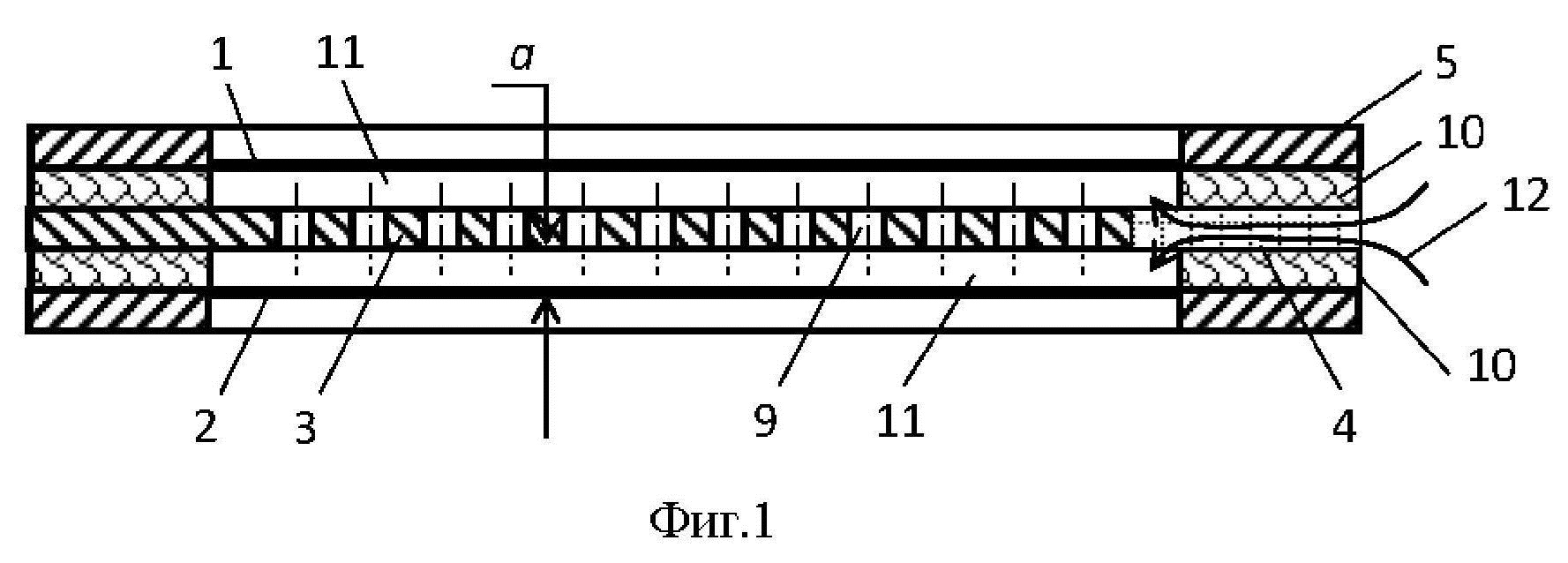
Description
Полезная модель относится к области акустических систем, в частности к громкоговорителям, осуществляющим преобразование электрического сигнала в звуковой, и предназначена для использования в акустических системах воспроизведения звука для бытовых и профессиональных целей.The utility model relates to the field of acoustic systems, in particular to loudspeakers that convert an electrical signal into sound, and is intended for use in acoustic sound reproduction systems for domestic and professional purposes.
Известен аналог - громкоговоритель электростатический - US 1082248, 13.08.1912, содержащий диафрагму, зажатую между двумя электропроводящими решетками, выполняющими роль статора, с обеспечением воздушного зазора между диафрагмой и статором, причем решетки статора и диафрагма подключены к источнику напряжения с обеспечением поляризации диафрагмы электростатическим полем статора.An analogue is known - an electrostatic loudspeaker - US 1082248, 08/13/1912, containing a diaphragm sandwiched between two electrically conductive grids that act as a stator, with an air gap between the diaphragm and the stator, and the stator grids and the diaphragm are connected to a voltage source to ensure the polarization of the diaphragm by an electrostatic field stator.
Недостатком аналога является наличие искажений создаваемого устройством звука. Искажения возникают из-за того, что заряженная диафрагма притягивает и накапливает на своей поверхности пыль. В результате возникают утечки заряда, возникают посторонние высокочастотные призвуки.The disadvantage of the analog is the presence of distortion of the sound produced by the device. Distortion occurs due to the fact that a charged diaphragm attracts and accumulates dust on its surface. As a result, charge leakage occurs, extraneous high-frequency overtones appear.
Известен аналог - громкоговоритель электростатический - источник в сети Интернет https://doctorhead.ru/product/stax_srx9000/, содержащий диафрагму, зажатую между двумя электропроводящими решетками, выполняющими роль статора, с обеспечением воздушного зазора между диафрагмой и статором, причем решетки статора и диафрагма подключены к источнику напряжения с обеспечением поляризации диафрагмы электростатическим полем статора, отличающийся тем, что снаружи решеток установлены защитные диафрагмы, исключающие попадание пыли и влаги в объем между решетками, в котором расположена рабочая диафрагма.An analog is known - an electrostatic loudspeaker - a source on the Internet https://doctorhead.ru/product/stax_srx9000/, containing a diaphragm sandwiched between two electrically conductive gratings that act as a stator, with an air gap between the diaphragm and the stator, and the stator gratings and the diaphragm connected to a voltage source providing the polarization of the diaphragm by the electrostatic field of the stator, characterized in that protective diaphragms are installed outside the gratings, preventing dust and moisture from entering the volume between the gratings, in which the working diaphragm is located.
Недостатком аналога является наличие искажений создаваемого устройством звука. Искажения возникают по трем причинам. Во-первых, при колебаниях диафрагмы между ней и всегда лишь частично прозрачными для звуковой волны решетками статора возникает избыточное давление, которое уменьшает амплитуду перемещения диафрагмы, изменяя тем самым характер звуковых колебаний, что является источником искажений. Во-вторых, импульс колебания рабочей диафрагмы при наличии защитных диафрагм через колебание воздуха передается решеткам статора, которые связаны с защитными диафрагмами. В результате статоры тоже совершают небольшие колебания в противофазе с колебаниями диафрагмы, что является источником искажений. В-третьих, при прохождении через отверстия решеток статора звуковая волна превращается из плоской во множество сферических, а достигнув защитной диафрагмы, снова превращается в плоскую волну. Указанные преобразования происходят с неизбежными потерями, что является источником искажений.The disadvantage of the analog is the presence of distortion of the sound produced by the device. Distortions arise for three reasons. Firstly, when the diaphragm vibrates between it and the stator gratings, which are always only partially transparent to the sound wave, excess pressure arises, which reduces the amplitude of the diaphragm movement, thereby changing the nature of the sound vibrations, which is a source of distortion. Secondly, in the presence of protective diaphragms, the impulse of oscillation of the working diaphragm is transmitted through air vibration to the stator gratings, which are connected to the protective diaphragms. As a result, the stators also make small oscillations out of phase with the oscillations of the diaphragm, which is a source of distortion. Thirdly, when passing through the holes of the stator gratings, the sound wave turns from a flat one into many spherical ones, and when it reaches the protective diaphragm, it again turns into a plane wave. These transformations occur with inevitable losses, which is a source of distortion.
Известен аналог - громкоговоритель электростатический – US 4246448, 20.01.1981, принятый в качестве прототипа, содержащий две диафрагмы, закрепленные с двух сторон относительно решетки, выполняющей роль статора, с зазорами от него, статор и диафрагмы подключены к источнику напряжения с обеспечением поляризации статора электростатическим полем диафрагм.An analogue is known - an electrostatic loudspeaker - US 4246448, 01/20/1981, adopted as a prototype, containing two diaphragms fixed on both sides relative to the grid that acts as a stator, with gaps from it, the stator and diaphragms are connected to a voltage source with electrostatic polarization of the stator aperture field.
Недостатком прототипа является наличие искажений создаваемого устройством звука. Искажения возникают из-за того, что заряженная решетка притягивает и накапливает на своей поверхности пыль. В результате возникают утечки заряда, возникают посторонние высокочастотные призвуки.The disadvantage of the prototype is the presence of distortion generated by the sound device. Distortions arise due to the fact that a charged grating attracts and accumulates dust on its surface. As a result, charge leakage occurs, extraneous high-frequency overtones appear.
Технический результат предлагаемой полезной модели заключается в снижении искажений звукового сигнала при его преобразовании из электрической формы в звуковое колебание воздушной среды.The technical result of the proposed utility model is to reduce the distortion of the audio signal when it is converted from an electrical form into a sound vibration of the air environment.
Технический результат достигается в громкоговорителе электростатическом пылезащищенном, содержащем две диафрагмы, закрепленные с двух сторон относительно статора, имеющего решетку, каждая диафрагма закреплена с зазором относительно решетки статора, диафрагмы подключены к источнику напряжения с обеспечением поляризации статора электростатическим полем диафрагм, в соединение диафрагмы со статором установлен фильтрующий элемент, соединяющий внутренний замкнутый объем между диафрагмами с атмосферой.The technical result is achieved in an electrostatic dust-proof loudspeaker containing two diaphragms fixed on both sides relative to the stator having a grating, each diaphragm is fixed with a gap relative to the stator grating, the diaphragms are connected to a voltage source to ensure the polarization of the stator by the electrostatic field of the diaphragms, a a filter element connecting the internal closed volume between the diaphragms with the atmosphere.
На фиг. 1 изображено поперечное сечение громкоговорителя электростатического пылезащищенного.In FIG. 1 shows a cross section of an electrostatic dustproof loudspeaker.
На фиг. 2 изображена взрыв-схема громкоговорителя электростатического пылезащищенного.In FIG. 2 shows an explosion diagram of an electrostatic dust-proof loudspeaker.
Громкоговоритель электростатический пылезащищенный содержит две диафрагмы 1, 2, как показано на фиг. 1, закрепленные с двух сторон относительно решетки 3, выполняющей роль статора, с зазорами а от него, статор 3 и диафрагмы 1, 2 подключены к источнику напряжения с обеспечением поляризации статора 3 электростатическим полем диафрагм 1, 2, в соединение диафрагмы 1 (2) со статором 3 установлен фильтрующий элемент 4, являющийся единственным путем попадания воздуха во внутренний объем между диафрагмами 1 и 2 из атмосферы.The electrostatic dust-proof loudspeaker contains two
Рассмотрим пример конкретной реализации громкоговорителя электростатического пылезащищенного. Громкоговоритель является динамиком наушников и размещен в пластиковом корпусе. Диафрагма 1 и 2 изготовлена из пластиковой полиэтилентерефталатовой пленки, покрытой проводящим материалом - графитом, и закреплена клеем на рамке 5, выполненной из стали, как показано на фиг. 1, 2. Рамка 5 имеет выступ 6, к которому пайкой присоединен провод (на фиг. не показан) подачи электропитания на диафрагму. Решетка 3 статора выполнена из металла и имеет выступ 7, к которому пайкой присоединен провод подачи электропитания. В решетке 3 статора имеется открытый с наружной стороны паз 8, в который установлен фильтрующий элемент 4. Фильтрующий элемент 4 изготовлен из пенополиуретановой губки. Фильтрующий элемент 4 может быть установлен в рамку 5 диафрагмы или зажат между диафрагмой и статором 3 с обеспечением герметизации остальных мест сопряжения диафрагмы и статора. Статор 3 имеет отверстия 9 для прохода воздуха при колебании диафрагм 1 и 2. Отверстия 9 образуют решетку статора. Воздушный зазор а обеспечивается за счет того, что между диафрагмой 1 (2) и решеткой 3 установлено изолирующее кольцо 10. Зазор также может быть обеспечен расположением рамки 5 со стороны решетки 3 и соединения их на герметик, обеспечивающий электроизоляцию. Весь пакет диафрагма - изолирующее кольцо - решетка - изолирующее кольцо - диафрагма собран с обеспечением герметичности при сопряжении деталей благодаря отсутствию зазора между ними и установке деталей на герметике. Возможна установка деталей через уплотняющие прокладки и стягивание пакета винтами или деталями корпуса громкоговорителя или наушников, который на фигурах не показан. Этим обеспечивается замкнутый объем 11 между диафрагмами 1 и 2, доступ воздуха в который обеспечивается только через фильтрующий элемент 4.Consider an example of a specific implementation of an electrostatic dust-proof loudspeaker. The loudspeaker is a headphone speaker and is housed in a plastic case.
Рассмотрим пример работы громкоговорителя электростатического пылезащищенного. В процессе работы звуковой сигнал подается в виде переменного напряжения на диафрагмы 1 и 2. В результате между диафрагмами возникает электростатическое поле, пропорциональное звуковому сигналу, создающее заряд на решетке статора 3. Возникающие между зарядами на статоре и диафрагмах кулоновские силы заставляют диафрагмы 1, 2 колебаться в соответствии с подаваемым звуковым сигналам. При этом устройство не содержит недостатков, присущих аналогам и прототипу.Consider an example of the operation of an electrostatic dust-proof loudspeaker. During operation, the sound signal is applied in the form of an alternating voltage to the
Элемент, который имеет постоянный заряд, притягивает пылинки, которые получили противоположный заряд. В первых двух аналогах таким элементом является диафрагма. В предлагаемой полезной модели элементом, который потенциально может притягивать пыль, является статор 3. Элементы, на которые подается переменный заряд - диафрагмы 1,2- пыль не накапливают, так как пылинки за один цикл смены заряда притягиваются и отталкиваются в соответствии со сменой знака заряда. Статор 3 с постоянным зарядом расположен между двух диафрагм 1, 2 в герметичном внутреннем объеме 11. При колебании диафрагм 1, 2 воздух внутрь этого объема к постоянно заряженному статору 3 попадает через фильтрующий элемент 4, на котором задерживается пыль. Воздушный поток 12, проходящий через фильтрующий элемент 4 показан на фиг. 1. Благодаря наличию фильтрующего элемента 4 отсутствует необходимость применения защитных диафрагм, как во втором аналоге, которые вносят искажения в звук. Отсутствие пыли во внутреннем объеме 11 между диафрагмами 1 и 2 исключает искажение звука, обусловленное прилипанием пыли к статору 3 и возникновением утечек заряда, а также появлением посторонних высокочастотных призвуков.An element that has a constant charge attracts dust particles that have received the opposite charge. In the first two analogues, such an element is the diaphragm. In the proposed utility model, the element that can potentially attract dust is the
Во время работы устройства две активные диафрагмы 1, 2 проталкивают воздух через одну решетку статора 3 так, что, когда одна диафрагма 1 работает на проталкивание, вторая 2 работает на втягивание и наоборот. В аналогах одна диафрагма совершает работу по проталкиванию воздуха через отверстия двух решеток статоров. Поэтому по сравнению с аналогами в полезной модели меньше инерционность - два активных элемента перемещают один объем воздуха, в то время как в аналогах два объема воздуха перемещает один активный элемент. Благодаря этому в полезной модели исключены искажения звука, связанные с описанным фактором инерционности.During operation of the device, two
В предложенной полезной модели между активной излучающей звук диафрагмой и ухом нет никаких препятствий, которые создают акустическую тень и дополнительные преобразования волнового фронта, в отличие от аналогов. Преобразование только одно - оно находится между диафрагмами и в излучении звука это преобразование не участвует, что также снижает искажения звука.In the proposed utility model, there are no obstacles between the active sound-emitting diaphragm and the ear, which create an acoustic shadow and additional wavefront transformations, unlike analogues. There is only one transformation - it is located between the diaphragms and this transformation is not involved in the sound emission, which also reduces sound distortion.
Claims (1)
Publications (1)
| Publication Number | Publication Date |
|---|---|
| RU215744U1 true RU215744U1 (en) | 2022-12-23 |
Family
ID=
Citations (6)
| Publication number | Priority date | Publication date | Assignee | Title |
|---|---|---|---|---|
| GB838024A (en) * | 1956-10-11 | 1960-06-22 | Pye Ltd | Improvements in electrostatic loudspeakers |
| CA908802A (en) * | 1972-08-29 | Lucy M. Bobb | Electrostatic speaker | |
| FR2100906B1 (en) * | 1970-07-14 | 1975-10-10 | Pioneer Electronic Corp | |
| FR2261675B1 (en) * | 1974-02-20 | 1977-07-08 | Tokyo Shibaura Electric Co | |
| FR2189974B1 (en) * | 1972-06-17 | 1978-01-06 | Sony Corp | |
| EP2150075A2 (en) * | 2008-07-31 | 2010-02-03 | HTC Corporation | Electronic device and electro-acoustic transducer thereof |
Patent Citations (6)
| Publication number | Priority date | Publication date | Assignee | Title |
|---|---|---|---|---|
| CA908802A (en) * | 1972-08-29 | Lucy M. Bobb | Electrostatic speaker | |
| GB838024A (en) * | 1956-10-11 | 1960-06-22 | Pye Ltd | Improvements in electrostatic loudspeakers |
| FR2100906B1 (en) * | 1970-07-14 | 1975-10-10 | Pioneer Electronic Corp | |
| FR2189974B1 (en) * | 1972-06-17 | 1978-01-06 | Sony Corp | |
| FR2261675B1 (en) * | 1974-02-20 | 1977-07-08 | Tokyo Shibaura Electric Co | |
| EP2150075A2 (en) * | 2008-07-31 | 2010-02-03 | HTC Corporation | Electronic device and electro-acoustic transducer thereof |
Similar Documents
| Publication | Publication Date | Title |
|---|---|---|
| US11838720B2 (en) | Vibration and sound-making apparatus and electronic device | |
| US3727719A (en) | Sound reproducing system | |
| CN107852554B (en) | Vibration transmission structure and piezoelectric speaker | |
| Bright et al. | Active control of loudspeakers: An investigation of practical applications | |
| KR20190123992A (en) | Hybrid actuator | |
| JP6990468B2 (en) | Thin handset | |
| GB2357215A (en) | Resonant panel loudspeakers | |
| WO2021138950A1 (en) | Speaker enclosure | |
| WO2021237837A1 (en) | Sound production device | |
| US3573397A (en) | Acoustic diaphragm and translating device utilizing same | |
| CN118678269A (en) | Sound producing device and electronic equipment | |
| RU215744U1 (en) | ELECTROSTATIC DUST PROOF LOUDSPEAKER | |
| WO2021237791A1 (en) | Sound production device | |
| GB1357403A (en) | Electroacoustic transducer | |
| WO2022007026A1 (en) | Loudspeaker apparatus and mobile terminal device | |
| KR20010108129A (en) | Compound electrolytic loudspeaker assembly | |
| CN209017314U (en) | A kind of electret microphone | |
| CN115361641B (en) | Loudspeaker module and sound box | |
| CN112261559B (en) | Loudspeaker | |
| CN115334406B (en) | Speakers | |
| CN210120642U (en) | Diaphragm type receiver | |
| JP3230459B2 (en) | Speaker | |
| CN110366064B (en) | A diaphragm receiver | |
| CN210120665U (en) | Multi-sound-cavity telephone receiver | |
| WO2021237814A1 (en) | Sound generating device |