RU2155100C2 - Agitating mill - Google Patents
Agitating mill Download PDFInfo
- Publication number
- RU2155100C2 RU2155100C2 RU98119389/03A RU98119389A RU2155100C2 RU 2155100 C2 RU2155100 C2 RU 2155100C2 RU 98119389/03 A RU98119389/03 A RU 98119389/03A RU 98119389 A RU98119389 A RU 98119389A RU 2155100 C2 RU2155100 C2 RU 2155100C2
- Authority
- RU
- Russia
- Prior art keywords
- grinding zone
- grinding
- zone
- wall
- mill
- Prior art date
Links
- 239000000463 material Substances 0.000 claims abstract description 46
- 238000000926 separation method Methods 0.000 claims description 19
- 230000001133 acceleration Effects 0.000 claims description 7
- 239000012530 fluid Substances 0.000 claims 1
- 210000001061 forehead Anatomy 0.000 claims 1
- 239000002245 particle Substances 0.000 abstract description 8
- 230000000694 effects Effects 0.000 abstract description 6
- 210000000056 organ Anatomy 0.000 abstract 2
- 238000003801 milling Methods 0.000 abstract 1
- 239000000126 substance Substances 0.000 abstract 1
- 239000006185 dispersion Substances 0.000 description 9
- 238000001816 cooling Methods 0.000 description 7
- 230000007704 transition Effects 0.000 description 7
- 239000000498 cooling water Substances 0.000 description 4
- 238000005498 polishing Methods 0.000 description 4
- 238000007599 discharging Methods 0.000 description 2
- 238000000034 method Methods 0.000 description 2
- 238000003756 stirring Methods 0.000 description 2
- 239000011362 coarse particle Substances 0.000 description 1
- 238000009499 grossing Methods 0.000 description 1
- 230000035939 shock Effects 0.000 description 1
- 239000000725 suspension Substances 0.000 description 1
Images
Classifications
-
- B—PERFORMING OPERATIONS; TRANSPORTING
- B02—CRUSHING, PULVERISING, OR DISINTEGRATING; PREPARATORY TREATMENT OF GRAIN FOR MILLING
- B02C—CRUSHING, PULVERISING, OR DISINTEGRATING IN GENERAL; MILLING GRAIN
- B02C17/00—Disintegrating by tumbling mills, i.e. mills having a container charged with the material to be disintegrated with or without special disintegrating members such as pebbles or balls
- B02C17/16—Mills in which a fixed container houses stirring means tumbling the charge
- B02C17/166—Mills in which a fixed container houses stirring means tumbling the charge of the annular gap type
Landscapes
- Engineering & Computer Science (AREA)
- Food Science & Technology (AREA)
- Crushing And Grinding (AREA)
Abstract
Description
Изобретение относится к устройствам для измельчения материалов и касается мельницы-мешалки. The invention relates to a device for grinding materials and relates to a mill-mixer.
Подобная мельница-мешалка известна из ЕР 0370022 В (соответственно, патент США 5062577). У этой мельницы-мешалки на ограничительных стенках внешней зоны измельчения и, по меньшей мере, на внутренней ограничительной стенке внутренней зоны измельчения расположены выступающие рабочие органы мешалки, благодаря которым происходит взаимное ускорение и торможение интенсификатора помола, что приводит к турбулентному характеру течения с эффектом размалывания и диспергирования, преимущественно, в результате соударения. Измельчаемый материал течет через пространство подачи измельчаемого материала, через переходную область в каналах перетекания во внешнюю зону измельчения и через отклоняющее пространство во внутреннюю зону измельчения. Интенсификатор помола проходит по контуру через внешнюю зону измельчения, отклоняющее пространство, внутреннюю зону измельчения и каналы перетекания назад во внешнюю зону измельчения, соответственно, во впадающую в нее область перехода. Измельчаемый материал течет из конца внутренней зоны измельчения к сепаратору. Сепаратор не оказывает существенного влияния на отделение интенсификатора помола от измельчаемого материала; все же понятие "разделительное устройство (сепаратор)" используется также и в этой заявке, так как оно вообще используется в специальной терминологии. Как следует из вышеописанного, отделение интенсификатора помола от измельчаемого материала происходит уже перед разделительным устройством. Известная мельница-мешалка очень хорошо зарекомендовала себя на практике. Such a mixer mill is known from EP 0370022 B (respectively, US patent 5062577). This agitator mill has protruding working elements of the agitator on the restrictive walls of the external grinding zone and at least on the internal restrictive wall of the internal grinding zone, due to which mutual acceleration and deceleration of the grinding intensifier occur, which leads to a turbulent flow with a grinding effect dispersion, mainly as a result of collision. The material to be ground flows through the feed space of the material to be ground, through the transition region in the flow channels to the external grinding zone and through the deflecting space to the internal grinding zone. The grinding intensifier passes along the contour through the external grinding zone, which deflects the space, the internal grinding zone and the flow channels back into the external grinding zone, respectively, into the transition region that flows into it. The material to be ground flows from the end of the inner grinding zone to the separator. The separator does not have a significant effect on the separation of the intensifier grinding from the crushed material; nevertheless, the concept of "separation device (separator)" is also used in this application, since it is generally used in special terminology. As follows from the above, the separation of the intensifier grinding from the crushed material occurs before the separation device. The well-known agitator mill has proven itself very well in practice.
Из DE 2811899C известна мельница-мешалка, внешняя зона измельчения которой, с одной стороны, и внутренняя зона измельчения, с другой стороны, сужаются в виде усеченного конуса, т.е. сечение зоны измельчения на каждой стороне срединной продольной оси ротора и статора имеет форму конуса. Измельчаемый материал течет по мельнице-мешалке изнутри наружу, т.е. втекает в нее через узкий диаметр внутренней зоны измельчения, затем протекает через радиально расширяющуюся внутреннюю зону измельчения, отклоняющее пространство и, наконец, через радиально расширяющуюся внешнюю зону измельчения. Оттуда он устремляется радиально внутрь мешалки через ограниченное с одной стороны мешалкой пространство к разделительному устройству, через которое отводится измельчаемый материал. Это разделительное устройство расположено после входа канала перетекания, вход которого расположен радиально внутри разделительного устройства, и таким образом расположен после него. Оттуда интенсификатор помола через каналы перетекания в роторе устремляется в начальную область внутренней зоны измельчения. Ограничительные стенки зоны измельчения являются гладкими. Ширина мелющей щели, т.е. радиальная ширина зоны измельчения, постоянна; однако, расстояние до оси вращения непрерывно возрастает. Отсюда получается, что градиент резания возрастает по пути движения измельчаемого материала изнутри наружу. Это приводит к тому, что он либо слишком низок во внутренней зоне измельчения, либо слишком высок во внешней зоне измельчения, что вызывает неравномерную нагрузку на измельчаемый материал. (Градиент резания определяется как отношение скорости вращающейся поверхности к ширине щели.)
В неопубликованном DE 19632757.1 A1 (соответственно, US-Serial N 08/906043) описана известная благодаря открытому предшествующему применению мельница-мешалка, внешняя и внутренняя зоны измельчения которой выполнены в виде мелющей щели. Эта мелющая щель выполнена гладкостенной, свободной от рабочих органов мешалки. Благодаря гладкостенному исполнению цилиндрических ограничительных стенок внешней и внутренней зон измельчения, образуется течение, в котором интенсификатор помола движется слоями относительно друг друга. Градиент резания и вместе с тем локальная интенсивность нагрузки постоянны, с одной стороны, во внешней зоне измельчения и, с другой стороны, во внутренней зоне измельчения по соответствующей высоте зоны измельчения.A mixer mill is known from DE 2811899C, the outer grinding zone of which, on the one hand, and the inner grinding zone, on the other hand, taper in the form of a truncated cone, i.e. the cross section of the grinding zone on each side of the median longitudinal axis of the rotor and stator has a conical shape. The milled material flows through the mill-mixer from the inside out, i.e. flows into it through the narrow diameter of the inner grinding zone, then flows through the radially expanding inner grinding zone, deflecting the space, and finally through the radially expanding outer grinding zone. From there, it rushes radially into the agitator through a space limited on one side of the agitator to a separation device through which the crushed material is discharged. This separation device is located after the entrance of the overflow channel, the input of which is located radially inside the separation device, and thus is located after it. From there, the intensifier grinding through the flow channels in the rotor rushes to the initial region of the inner grinding zone. The boundary walls of the grinding zone are smooth. The width of the grinding gap, i.e. the radial width of the grinding zone is constant; however, the distance to the axis of rotation is continuously increasing. It turns out that the cutting gradient increases along the path of movement of the crushed material from the inside out. This leads to the fact that it is either too low in the inner grinding zone, or too high in the outer grinding zone, which causes an uneven load on the crushed material. (The cutting gradient is defined as the ratio of the speed of the rotating surface to the width of the slit.)
In unpublished DE 19632757.1 A1 (respectively, US-Serial N 08/906043) describes a mixer mill known for its open prior use, the outer and inner grinding zones of which are made in the form of a grinding slit. This grinding slot is made smooth, free from the working bodies of the mixer. Due to the smooth-walled execution of the cylindrical boundary walls of the external and internal grinding zones, a flow is formed in which the grinding intensifier moves in layers relative to each other. The cutting gradient and, at the same time, the local load intensity are constant, on the one hand, in the outer grinding zone and, on the other hand, in the inner grinding zone at the corresponding height of the grinding zone.
Из DE 3844380 C1 известна мельница-мешалка, которая имеет вал мешалки с клеткой, являющейся частью вала мешалки. Клетка расположена на опоре, между которой и крышкой резервуара помола и смежной областью внутренней стенки резервуара помола образована щель перетирания. В этой щели перетирания измельчаемый материал активизируется трением ограничивающих эту щель перетирания стенок резервуара помола и вала мешалки. A mixer mill is known from DE 3844380 C1, which has a mixer shaft with a cage that is part of the mixer shaft. The cell is located on a support, between which a grinding gap is formed between the lid of the grinding tank and the adjacent region of the inner wall of the grinding tank. In this grinding gap, the milled material is activated by the friction of the grinding vessel and the mixer shaft bounding this grinding gap.
В основе изобретения лежит задача разработать мельницу-мешалку родового вида так, чтобы сохранялось интенсивное измельчение и диспергирование частиц измельчаемого материала, однако, поверхность измельчаемых частиц получалась тонко выровненной. The basis of the invention is the task of developing a generic-type stirring mill so that intensive grinding and dispersion of particles of the material to be ground is maintained, however, the surface of the particles to be ground is finely aligned.
Согласно изобретению, эта задача решается признаками в отличительной части пункта 1. Во внешней зоне измельчения - как у родовой мельницы-мешалки - происходит интенсивное измельчение и диспергирование частиц измельчаемого материала, преимущественно, в результате ударного эффекта, то есть происходит ударное измельчение. Время пребывания измельчаемого материала во внешней зоне измельчения - по сравнению с временем пребывания во внутренней зоне измельчения - очень велико. Во внутренней зоне измельчения происходит сглаживание, то есть разновидность полирования поверхности вновь созданных во внешней зоне в результате измельчения частиц помола, то есть полирующее измельчение. При переходе от внешней зоны измельчения к внутренней зоне измельчения происходит достаточное ускорение измельчаемого материала. В пункте 2 указано, каким образом можно оптимизировать это ускорение. According to the invention, this problem is solved by the features in the distinguishing part of paragraph 1. In the external grinding zone — like a generic agitator mill — intensive grinding and dispersion of particles of the crushed material occurs, mainly as a result of the impact effect, that is, impact grinding occurs. The residence time of the material being ground in the external grinding zone is very long compared to the residence time in the internal grinding zone. In the inner grinding zone, smoothing occurs, that is, a type of polishing of the surfaces newly created in the outer zone as a result of grinding of grinding particles, i.e., polishing grinding. When switching from the external grinding zone to the internal grinding zone, sufficient acceleration of the crushed material occurs.
Пункты 3 и 4 дают предпочтительный нижний диапазон отношения площади поперечного сечения внешней зоны измельчения к площади поперечного сечения внутренней зоны измельчения. Пункты 5 и 6 дают предпочтительный верхний диапазон отношения площади поперечного сечения внешней зоны измельчения к площади поперечного сечения внутренней зоны измельчения. Paragraphs 3 and 4 give a preferred lower range of the ratio of the cross-sectional area of the outer grinding zone to the cross-sectional area of the inner grinding zone.
В пунктах 7-10 даны предпочтительные граничные значения радиальной ширины внешней и внутренней зон измельчения. Paragraphs 7–10 give preferred boundary values for the radial width of the outer and inner grinding zones.
В пункте 11 указаны меры, в результате которых можно оптимизировать ударное измельчение во внешней зоне измельчения. In
В пунктах 12-16 дается следующий вариант исполнения, в котором измельчаемый материал перед входом во внешнюю зону измельчения подвергается предварительному диспергированию в узкой цилиндрической вихревой щели. Этот эффект вызывается, в частности, тем, что цилиндрическая вихревая щель имеет очень небольшую протяженность радиально к срединной продольной оси, и что каналы перетекания входят в эту вихревую щель, так что ограничивающие вихревую щель участки стенки ротора и выходные отверстия каналов перетекания расположены попеременно на внутренней стенке резервуара помола. In paragraphs 12-16, the following embodiment is given, in which the material to be ground before entering the external grinding zone is subjected to preliminary dispersion in a narrow cylindrical vortex gap. This effect is caused, in particular, by the fact that the cylindrical vortex gap has a very small extent radially to the median longitudinal axis, and that the flow channels enter this vortex gap, so that the rotor wall sections and the outlet openings of the flow channels limiting the vortex slot are alternately located on the inner grinding tank wall.
Дальнейшие признаки, преимущества и подробности изобретения видны из нижеследующего описания примера исполнения изобретения на основании чертежей. На них показано:
фиг. 1 - схематическое изображение мельницы-мешалки (вид сбоку),
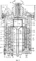
фиг. 2 - продольное сечение резервуара помола мельницы-мешалки и
фиг. 3 - продольное сечение резервуара помола измененной формы исполнения мельницы-мешалки.Further features, advantages and details of the invention are apparent from the following description of an example embodiment of the invention based on the drawings. They show:
FIG. 1 is a schematic illustration of a stirring mill (side view),
FIG. 2 is a longitudinal section of a grinding tank of a mill-mixer and
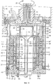
FIG. 3 is a longitudinal section of a grinding tank of an altered form of a mill-mixer.
Изображенная на фиг. 1 мельница-мешалка имеет, как обычно, станину 1, на которой установлен цилиндрический резервуар помола 2. На станине 1 закреплен электрический приводной двигатель 3, который снабжен клиноременным шкивом 4, от которого через клиновой ремень 5 приводится в действие жестко связанный с приводным валом 6 клиноременный шкив 7. Depicted in FIG. 1, the mill-mixer has, as usual, a frame 1 on which a cylindrical grinding tank is mounted 2. An electric drive motor 3 is mounted on the frame 1, which is equipped with a V-belt pulley 4, from which it is rigidly connected to the drive shaft through a V-belt 5 V-belt pulley 7.
Как, в частности, следует из фиг. 2, резервуар помола 2 состоит из цилиндрической, окружающей зону измельчения 8 внутренней стенки 9, которая окружена, по существу, цилиндрическим внешним кожухом 10. Внутренняя стенка 9 и внешний кожух 10 ограничивают собой охлаждающую камеру 11. Нижнее окончание зоны измельчения 8 образовано кольцевой пластиной основания 12, закрепленной на резервуаре помола винтами 13. As, in particular, follows from FIG. 2, the
Резервуар помола 2 имеет верхний кольцевой фланец 14, посредством которого он закреплен винтами 15 на нижней стороне несущего кожуха 16, который укреплен на станине 1 мельницы-мешалки. Зона измельчения 8 закрыта крышкой 17. Несущий кожух 16 имеет корпус 18 для подшипника и уплотнения, расположенный по центру коаксиально к центральной продольной оси 19 резервуара помола 2. Через этот корпус 18 проходит также расположенный коаксиально оси 19 приводной вал 6, на котором расположена мешалка 20. В смежную с зоной измельчения 8 область корпуса 18 входит трубопровод подачи помола 21. The
На кольцевой пластине основания 12 укреплен выступающий в зону измельчения 8 горшкообразный цилиндрический внутренний статор 22, состоящий из ограничивающего зону измельчения 8 коаксиального оси 19 наружного цилиндрического кожуха 23 и коаксиального оси 19 внутреннего цилиндрического кожуха 24. Наружный кожух 23 и внутренний кожух 24 ограничивают камеру охлаждения 25. Камера охлаждения 25 связана с камерой охлаждения 26 на пластине основания 12, к которой через подающий штуцер 27 подводится вода для охлаждения, отводящаяся через выпускной штуцер 27a. К камере охлаждения 11 резервуара помола 2 через подающий штуцер 28 подается вода для охлаждения, отводящаяся через выпускной штуцер 29. A pot-shaped cylindrical
На находящемся поверх зоны измельчения 8 торце 30 внутреннего статора 22 расположено разделительное устройство 31 для разделения помола - интенсификатор помола, соединенное с отводящим трубопроводом 32. Между разделительным устройством 31 и отводящим трубопроводом 32 предусмотрен направляющий сборник 33. Отводящий трубопровод 32 в области пластины основания 12 снабжен поддерживающей скобой 34, разъемно соединенной посредством винтов 35 с пластиной основания 12 и, соответственно, с жестко соединенным с ней внутренним статором 22. Разделительное устройство 31 уплотняется на кольцевом торце 30 внутреннего статора 22 при помощи уплотнения 36 и может быть удалено после отворачивания винтов 35 вместе с отводящим трубопроводом 32 и направляющим сборником 33 из внутреннего статора 22 вниз. Разделительное устройство 31 может, таким образом, удаляться из зоны измельчения 8, без удаления находящегося в нем интенсификатора помола 37, так как при неработающей мешалке 20 зона измельчения 8 не заполнена до торца 30 этим интенсификатором помола 37. On the
Мешалка 20 в своей основе имеет форму горшка, то есть является по существу цилиндрическим ротором 38, образованным цилиндрической наружной стенкой 39 и коаксиально к ней и коаксиально к оси 19 расположенной цилиндрической внутренней стенкой 40. Между наружной стенкой 39 и внутренней стенкой 40 ротора 38 имеется камера охлаждения 41. Ротор 38 закреплен на несущей детали ротора 42, связанной с валом 6. Подвод и отвод охлаждающей воды к камере охлаждения 41 производится через каналы охлаждающей воды 43, 44, имеющиеся в несущей детали ротора 42 и на валу 6. Гладкой внутренней стенкой 9 резервуара помола 2 и гладкой цилиндрической наружной стенкой 39 ротора 38, с одной стороны, и цилиндрической гладкой внутренней стенкой 40 ротора 38 и цилиндрическим гладкостенным наружным кожухом 23 внутреннего статора 22, с другой стороны, зона измельчения 8 разделяется на цилиндрическую кольцевую наружную зону измельчения 8' с одной стороны и цилиндрическую кольцевую внутреннюю зону измельчения 8" с другой стороны, которые связаны друг с другом отклоняющим пространством 45 в области пластины основания 12. The
На ограничительных стенках зоны измельчения, образованных внутренней стенкой 9 и наружной стенкой 39, во внешней зоне измельчения 8' расположены выступающие неподвижные рабочие органы мешалки 46 и, соответственно, вращающиеся с ротором 38 рабочие органы мешалки 47. На ограничительных стенках зоны измельчения, образованных внутренней стенкой 40 и наружным кожухом 23, нет никаких выступающих во внутреннюю зону измельчения 8'' рабочих органов мешалки. Измельчаемый материал подается через зону измельчения 8 в соответствии со стрелками направления потока 48 от трубопровода подачи измельчаемого материала 21, проходя через пространство подачи измельчаемого материала 49 между несущей деталью ротора 42 с одной стороны и крышкой 17 и смежной областью внутренней стенки 9 с другой стороны, через внешнюю зону измельчения 8' вниз, через отклоняющее пространство 45 радиально внутрь и оттуда через внутреннюю зону измельчения 8'' вверх до разделительного устройства 31. На пути через внешнюю зону измельчения 8', отклоняющее пространство 45 и внутреннюю зону измельчения 8'' измельчаемый материал обрабатывается вращающейся мешалкой 20 вместе с интенсификатором помола 37. Измельчаемый материал покидает зону измельчения 8 через разделительное устройство 31, откуда он стекает через отводящий измельчаемый материал трубопровод 32. Служащее для отделения интенсификатора помола 37 разделительное устройство 31 расположено в цилиндрической выемке 50 несущей детали ротора 42. Между цилиндрической стенкой 51 выемки 50 и разделительным устройством 31 на стенке 51 расположены вытянутые по сечению треугольные захваты 52, образующие по сечению воронкообразные зоны входа для каналов перетекания 53. Подобное исполнение с такими захватами 52 известно из ЕР 0439826 B (соответственно, US-PS 5133508). On the bounding walls of the grinding zone formed by the
Каналы перетекания 53 находятся в несущей детали ротора 42, а именно, в области перехода от несущей детали ротора 42 к цилиндрическому ротору 38 и - смотря по направлению стрелок направления потока 48 - перед разделительным устройством 31. Они соединяют - относительно направления потока в соответствии со стрелками направления потока 48 - конец внутренней зоны измельчения 8'' с началом внешней зоны измельчения 8', то есть, с переходной областью 54 пространства подачи измельчаемого материала 49, переходящей во внешнюю зону измельчения 8'. Каналы перетекания 53 проходят - относительно направления вращения 55 мешалки 20 - радиально изнутри наружу против направления вращения 55, так что во внутренней зоне измельчения 8'' снабженный центробежным ускорением интенсификатор помола 37 отбрасывается через каналы перетекания 53 и снова возвращается в пространство подачи измельчаемого материала 49. The
Внешняя зона измельчения 8' с расположенными на роторе 38 рабочими органами мешалки 47 и расположенными в резервуаре помола 2 неподвижными ответными рабочими органами мешалки 46 образуют собственно зону измельчения, в которой интенсификатор помола 37 участвует в интенсивном обмене импульсом с вращающимися рабочими органами мешалки 47 и неподвижными рабочими органами мешалки 46, при этом измельчаемый материал подвергается интенсивному процессу резания и диспергирования в результате ударного эффекта. Во внешней зоне измельчения 8' отдельные частицы измельчаемого материала, подаваемые в виде дисперсии или суспензии, интенсивно измельчаются. Напротив, внутренняя зона измельчения 8" выполнена как мелющая щель, площадь поперечного сечения которой значительно меньше, чем площадь поперечного сечения внешней зоны измельчения 8'. Внешняя зона измельчения 8' имеет наружный диаметр Da и внутренний диаметр Di. Выполненная в виде мелющей щели внутренняя зона измельчения 8'' имеет наружный диаметр da и внутренний диаметр di. Для отношения площадей поперечного сечения внешней зоны измельчения 8' и внутренней зоны измельчения 8'' справедливо 4'' ≤ (Da2 - Di2)/(da2 - di2) и предпочтительно 5'' ≤ (Da2 - Di2)/(da2 - di2). Другими словами, это означает, что площадь поперечного сечения внешней зоны измельчения 8' в 4 или, соответственно, 5 раз больше, чем площадь поперечного сечения внутренней зоны измельчения 8''. Это приводит к тому, что скорость потока измельчаемого материала во внутренней зоне измельчения 8'', по меньшей мере, в 4 или 5 раз больше, чем во внешней зоне измельчения. Соответственно, время пребывания измельчаемого материала во внешней зоне измельчения 8' больше примерно в 4 или 5 раз, чем время пребывания измельчаемого материала в выполненной в виде мелющей щели внутренней зоне измельчения 8''. The external grinding zone 8 'with the working bodies of the
В качестве верхнего граничного значения отношения площадей поперечного сечения внешней зоны измельчения 8' и внутренней зоны измельчения 8'' получаются следующие значения: (Da2 - Di2)/(da2 - di2) ≤ 30 и предпочтительно (Da2 - Di2)/(da2 - di2) ≤ 25.As the upper boundary value of the ratio of the cross-sectional areas of the outer grinding zone 8 'and the inner grinding zone 8'', the following values are obtained: (Da 2 - Di 2 ) / (da 2 - di 2 ) ≤ 30 and preferably (Da 2 - Di 2 ) / (da 2 - di 2 ) ≤ 25.
Для ширины а внешней зоны измельчения 8', измеренной радиально к оси 19, справедливо: а ≥ 15 мм. Для верхнего граничного значения справедливо: а ≤ 300 мм. Для ширины щели b внутренней зоны измельчения, также измеренной радиально к оси 19, справедливо: b ≥ 3 мм. Для верхнего граничного значения - b ≤ 15 мм. При этом справедливо, что ширина щели b должна быть, по меньшей мере, в 4 раза больше диаметра с интенсификатора помола 37. В качестве верхнего граничного значения диаметра с интенсификатора помола 37 принимается значение с ≤ 1,5 мм. For the width a of the outer grinding zone 8 ', measured radially to the
Чтобы обеспечить возможность значительного ускорения измельчаемого материала при переходе от внешней зоны измельчения 8' к выполненной в виде мелющей щели внутренней зоне измельчения 8'', отклоняющее пространство 45 снабжено непрерывно сужающимся к внутренней зоне измельчения участком ускорения 56, действующим как форсунка. In order to allow significant acceleration of the crushed material during the transition from the
В то время как во внешней зоне измельчения 8' происходит в значительной мере турбулентный процесс измельчения, во внутренней зоне измельчения 8'', благодаря гладкостенным цилиндрическим ограничительным стенкам, образуется течение, в котором интенсификатор помола 37 движется слоями относительно друг друга. Градиент резания, а также локальная интенсивность нагружения постоянны по высоте во внутренней зоне измельчения 8''. Из-за незначительного времени пребывания измельчаемого материала во внутренней зоне измельчения 8'' и слоистого относительного движения интенсификатора помола 37 больше не происходит высокоинтенсивное диспергирование и измельчение, а только обработка проскользнувшей грубой частицы и, соответственно, округление и обработка вновь созданных во внешней зоне измельчения 8' поверхностей частиц. Таким образом происходит полирование отдельной частицы измельчаемого материала. While a largely turbulent grinding process takes place in the external grinding zone 8 ', in the inner grinding zone 8', due to the smooth-walled cylindrical boundary walls, a flow is formed in which the grinding
Описанная мельница-мешалка может располагаться вертикально или горизонтально, то есть иметь, как описано, вертикальную центральную продольную ось 19 или, соответственно, горизонтально расположенную центральную продольную ось. В частности, при горизонтальном расположении мельницы-мешалки не требуется захват 52. Впрочем, разумеется, могут потребоваться другие конструктивные приспособления. The described mixer mill can be located vertically or horizontally, that is, have, as described, a vertical central
Вариант исполнения по фиг. 3 отличается от варианта по фиг. 2 только исполнением цилиндрической стенки 57 несущей детали 42' ротора 38'. Между этой стенкой 57 и соответствующей внутренней стенкой 9 резервуара помола 2 имеется вихревая щель 58, с которой соединена коническая область пространства подачи измельчаемого материала 49. Каналы перетекания 53' соединены с вихревой щелью 58. В переходной области 54 несущей детали ротора 42' каналы перетекания 53' закрыты ограничителем 59, так что интенсификатор помола 37 в переходной области 54 может попасть непосредственно не во внешнюю зону измельчения 8', а только в вихревую щель 58. The embodiment of FIG. 3 differs from the embodiment of FIG. 2 only by the execution of the
Ширина e вихревой щели 58, измеренная радиально к центральной продольной оси 19, очень незначительна. Она определена условием:
3 мм ≤ e ≤ 8 мм
и, в частности,
4 мм ≤ e ≤ 5 мм.The width e of the vortex slit 58, measured radially to the central
3 mm ≤ e ≤ 8 mm
and in particular,
4 mm ≤ e ≤ 5 mm.
Далее, для отношения ширины щели e к диаметру c интенсификатора помола 37 действует условие:
3 c ≤ e ≤ 4 с.Further, for the ratio of the width of the slit e to the diameter c of the intensifier grinding 37, the condition applies:
3 s ≤ e ≤ 4 s.
Так как вихревая щель 58 по отношению к внешней зоне измельчения 8' имеет очень малое поперечное сечение, то скорость течения измельчаемого материала в вихревой щели 58 по направлению к внешней зоне измельчения 8' очень высока, так что исключается утечка интенсификатора помола 37 в коническую область пространства подачи измельчаемого материала 49. В частности, благодаря тому, что участки 60 цилиндрической стенки 57, прерывающиеся соответствующим выходом 61 каналов перетекания 53', чередуются с каналами перетекания 53', как бы образующими углубление, достигается очень интенсивное завихрение интенсификатора помола 37, приводящее к чрезвычайно интенсивному предварительному диспергированию измельчаемого материала в вихревой щели 58. Благодаря такому варианту осуществления изобретения, получается чрезвычайно эффективное последовательное соединение предварительного диспергирования, ударного измельчения и полирующего измельчения. Since the vortex slit 58 with respect to the external grinding zone 8 'has a very small cross section, the flow rate of the milled material in the
Claims (16)
4 ≤ (Da2 - Di2) / (da2 - di2),
где Da - наружный диаметр внешней зоны измельчения;
Di - внутренний диаметр внешней зоны измельчения;
da - наружный диаметр внутренней зоны измельчения;
di - внутренний диаметр внутренней зоны измельчения.3. The mill mixer according to claim 1 or 2, characterized in that the ratio of the cross-sectional area of the external grinding zone to the cross-sectional area of the inner grinding zone is determined by the condition
4 ≤ (Da 2 - Di 2 ) / (da 2 - di 2 ),
where Da is the outer diameter of the outer grinding zone;
Di is the inner diameter of the external grinding zone;
da is the outer diameter of the inner grinding zone;
di is the inner diameter of the inner grinding zone.
5 ≤ (Da2 - Di2) / (da2 - di2),
где Da - наружный диаметр внешней зоны измельчения;
Di - внутренний диаметр внешней зоны измельчения;
da - наружный диаметр внутренней зоны измельчения;
di - внутренний диаметр внутренней зоны измельчения.4. The mill mixer according to claim 3, characterized in that the ratio of the cross-sectional area of the external grinding zone to the cross-sectional area of the inner grinding zone is determined by the condition
5 ≤ (Da 2 - Di 2 ) / (da 2 - di 2 ),
where Da is the outer diameter of the outer grinding zone;
Di is the inner diameter of the external grinding zone;
da is the outer diameter of the inner grinding zone;
di is the inner diameter of the inner grinding zone.
(Da2 - Di2) / (da2 - di2) ≤ 30,
где Da - наружный диаметр внешней зоны измельчения;
Di - внутренний диаметр внешней зоны измельчения;
da - наружный диаметр внутренней зоны измельчения;
di - внутренний диаметр внутренней зоны измельчения.5. The mill mixer according to any one of claims 1 to 4, characterized in that the ratio of the cross-sectional area of the external grinding zone to the cross-sectional area of the inner grinding zone is determined by the condition
(Da 2 - Di 2 ) / (da 2 - di 2 ) ≤ 30,
where Da is the outer diameter of the outer grinding zone;
Di is the inner diameter of the external grinding zone;
da is the outer diameter of the inner grinding zone;
di is the inner diameter of the inner grinding zone.
(Da2 - Di2) / (da2 - di2) ≤ 25,
где Da - наружный диаметр внешней зоны измельчения;
Di - внутренний диаметр внешней зоны измельчения;
da - наружный диаметр внутренней зоны измельчения;
di - внутренний диаметр внутренней зоны измельчения.6. The mill-mixer according to claim 5, characterized in that the ratio of the cross-sectional area of the outer grinding zone to the cross-sectional area of the inner grinding zone is determined by the condition
(Da 2 - Di 2 ) / (da 2 - di 2 ) ≤ 25,
where Da is the outer diameter of the outer grinding zone;
Di is the inner diameter of the external grinding zone;
da is the outer diameter of the inner grinding zone;
di is the inner diameter of the inner grinding zone.
a ≥ 15 мм.7. The mill mixer according to any one of claims 1 to 6, characterized in that the width a of the outer grinding zone is determined by the condition
a ≥ 15 mm.
a ≤ 300 мм.8. The mill mixer according to any one of claims 1 to 7, characterized in that the width a of the external grinding zone is determined by the condition
a ≤ 300 mm.
b ≥ 3 мм.9. The mill mixer according to any one of paragraphs.1 to 8, characterized in that the width b of the slit of the inner grinding zone is determined by the condition
b ≥ 3 mm.
b ≤ 15 мм.10. The mill mixer according to any one of claims 1 to 9, characterized in that the width b of the slit of the inner grinding zone is determined by the condition
b ≤ 15 mm.
3 мм ≤ e ≤ 8 мм.14. The mill mixer according to item 12 or 13, characterized in that the width e of the vortex gap between the cylindrical wall and the inner wall of the grinding tank, measured radially to the central longitudinal axis, is determined by the condition
3 mm ≤ e ≤ 8 mm.
4 мм ≤ e ≤ 5 мм.15. The mill mixer according to 14, characterized in that the width e of the slit is determined by the condition
4 mm ≤ e ≤ 5 mm.
3c ≤ e ≤ 4c.16. The mill mixer according to 14, characterized in that the ratio of the width e to the diameter c of the grinding intensifier is determined by the condition
3c ≤ e ≤ 4c.
28.10.97 по пп. 1 - 11;
30.07.98 по пп.11 - 16.Priority on points:
10/28/97 according to paragraphs 1 to 11;
07/30/98 according to claims 11-16.
Applications Claiming Priority (4)
| Application Number | Priority Date | Filing Date | Title |
|---|---|---|---|
| DE19747474.8 | 1997-10-28 | ||
| DE19747474 | 1997-10-28 | ||
| DE19834397.3 | 1998-07-30 | ||
| DE19834397A DE19834397B4 (en) | 1997-10-28 | 1998-07-30 | agitating mill |
Publications (2)
| Publication Number | Publication Date |
|---|---|
| RU98119389A RU98119389A (en) | 2000-08-20 |
| RU2155100C2 true RU2155100C2 (en) | 2000-08-27 |
Family
ID=26041142
Family Applications (1)
| Application Number | Title | Priority Date | Filing Date |
|---|---|---|---|
| RU98119389/03A RU2155100C2 (en) | 1997-10-28 | 1998-10-26 | Agitating mill |
Country Status (8)
| Country | Link |
|---|---|
| US (1) | US5897068A (en) |
| EP (1) | EP0913200B1 (en) |
| JP (1) | JPH11197526A (en) |
| CN (1) | CN1101732C (en) |
| BR (1) | BR9804288A (en) |
| ES (1) | ES2195251T3 (en) |
| RU (1) | RU2155100C2 (en) |
| TW (1) | TW455508B (en) |
Cited By (2)
| Publication number | Priority date | Publication date | Assignee | Title |
|---|---|---|---|---|
| RU2555915C2 (en) * | 2010-12-04 | 2015-07-10 | Неч-Файнмальтехник Гмбх | Dynamic element for separator assembly of ball mill with mixer |
| RU2663485C2 (en) * | 2013-07-08 | 2018-08-06 | Неч-Файнмальтехник Гмбх | Mixing ball mill with axial channels |
Families Citing this family (14)
| Publication number | Priority date | Publication date | Assignee | Title |
|---|---|---|---|---|
| DE19819967B4 (en) * | 1998-05-05 | 2007-04-26 | BüHLER GMBH | agitating mill |
| DE29814714U1 (en) * | 1998-08-17 | 1998-12-10 | Draiswerke Gmbh, 68305 Mannheim | Agitator mill |
| EP1867394A3 (en) * | 2000-04-26 | 2008-03-05 | Elan Pharma International Ltd. | Apparatus for sanitary wet milling |
| DK1313564T3 (en) * | 2000-04-26 | 2010-04-06 | Elan Pharma Int Ltd | Appliance for hygienic wet grinding |
| JP4451965B2 (en) * | 2000-05-18 | 2010-04-14 | 株式会社井上製作所 | Pipeline bead mill |
| ATE361146T1 (en) * | 2005-05-19 | 2007-05-15 | Buehler Ag | AGITATOR MILL |
| KR100928076B1 (en) | 2008-12-19 | 2009-11-23 | (주)제이분체 | Stirred ball mill |
| KR20180021209A (en) | 2009-02-03 | 2018-02-28 | 이머리스 그래파이트 앤드 카본 스위춰랜드 리미티드 | New graphite material |
| CN103418462B (en) * | 2012-05-18 | 2015-07-08 | 昆山市密友粉体设备工程有限公司 | Structure of nano grade bead mill and dispersing and mixing system of environment-friendly intelligent bead mill |
| CN103480463B (en) * | 2012-06-14 | 2015-01-28 | 谢小飞 | Centrifugation type separation mesh-free material and bead separation medium stirring mill |
| CN102814217A (en) * | 2012-08-31 | 2012-12-12 | 常州市龙鑫化工机械有限公司 | Efficient recycling bead mill |
| EP3799960A1 (en) * | 2019-10-01 | 2021-04-07 | Bühler AG | Agitator mill |
| EP3946741B1 (en) * | 2020-03-27 | 2023-08-23 | Bühler AG | Agitator ball mill |
| EP4151314B1 (en) * | 2021-09-20 | 2024-02-21 | Bühler AG | Rotor |
Family Cites Families (14)
| Publication number | Priority date | Publication date | Assignee | Title |
|---|---|---|---|---|
| CH618893A5 (en) * | 1977-04-29 | 1980-08-29 | Buehler Ag Geb | |
| DE2811899C2 (en) | 1978-03-18 | 1984-12-06 | Fryma-Maschinen Ag, Rheinfelden | Gap ball mill |
| DE3345680A1 (en) * | 1983-12-16 | 1985-06-20 | Gebrüder Netzsch, Maschinenfabrik GmbH & Co, 8672 Selb | AGITATOR MILL |
| DE3444575A1 (en) * | 1984-12-06 | 1986-06-12 | Fryma-Maschinen Ag, Rheinfelden | BALL MILL |
| GB8431294D0 (en) * | 1984-12-12 | 1985-01-23 | Smidth & Co As F L | Controlling intermittant voltage supply |
| DE3716587C1 (en) | 1987-05-18 | 1988-04-28 | Draiswerke Gmbh | Agitator mill |
| DE3723558A1 (en) * | 1987-07-16 | 1989-01-26 | Netzsch Erich Holding | MILL, ESPECIALLY AGITATOR MILL |
| DE3844380C1 (en) | 1988-12-30 | 1990-01-18 | Erich Netzsch Gmbh & Co Holding Kg, 8672 Selb, De | Agitator mill with separating device in a rotating cage |
| DE4002613A1 (en) * | 1990-01-30 | 1991-08-01 | Draiswerke Gmbh | AGITATOR MILL |
| DE4010926A1 (en) * | 1990-04-04 | 1991-10-10 | Fryma Masch Ag | Mill using grinder bodies - has rotary centrifuging funnel widening in discharge direction of bodies |
| CH688849A5 (en) * | 1993-02-25 | 1998-04-30 | Buehler Ag | Agitator mill. |
| JPH07328405A (en) * | 1994-06-06 | 1995-12-19 | Mitsubishi Heavy Ind Ltd | Wet medium dispersing device |
| JPH08164342A (en) * | 1994-12-12 | 1996-06-25 | Mitsubishi Heavy Ind Ltd | Blade type wet medium disperser |
| DE19632757A1 (en) | 1996-08-14 | 1998-02-19 | Draiswerke Gmbh | Agitator mill |
-
1998
- 1998-10-10 EP EP98119177A patent/EP0913200B1/en not_active Expired - Lifetime
- 1998-10-10 ES ES98119177T patent/ES2195251T3/en not_active Expired - Lifetime
- 1998-10-15 US US09/172,887 patent/US5897068A/en not_active Expired - Lifetime
- 1998-10-23 JP JP10303044A patent/JPH11197526A/en active Pending
- 1998-10-26 RU RU98119389/03A patent/RU2155100C2/en not_active IP Right Cessation
- 1998-10-27 BR BR9804288-2A patent/BR9804288A/en not_active IP Right Cessation
- 1998-10-27 TW TW087117747A patent/TW455508B/en not_active IP Right Cessation
- 1998-10-28 CN CN98123476A patent/CN1101732C/en not_active Expired - Lifetime
Cited By (2)
| Publication number | Priority date | Publication date | Assignee | Title |
|---|---|---|---|---|
| RU2555915C2 (en) * | 2010-12-04 | 2015-07-10 | Неч-Файнмальтехник Гмбх | Dynamic element for separator assembly of ball mill with mixer |
| RU2663485C2 (en) * | 2013-07-08 | 2018-08-06 | Неч-Файнмальтехник Гмбх | Mixing ball mill with axial channels |
Also Published As
| Publication number | Publication date |
|---|---|
| JPH11197526A (en) | 1999-07-27 |
| ES2195251T3 (en) | 2003-12-01 |
| CN1101732C (en) | 2003-02-19 |
| TW455508B (en) | 2001-09-21 |
| CN1215632A (en) | 1999-05-05 |
| BR9804288A (en) | 1999-12-07 |
| US5897068A (en) | 1999-04-27 |
| EP0913200B1 (en) | 2003-04-23 |
| EP0913200A1 (en) | 1999-05-06 |
Similar Documents
| Publication | Publication Date | Title |
|---|---|---|
| RU2155100C2 (en) | Agitating mill | |
| RU2138334C1 (en) | Mill-mixer | |
| KR950007586B1 (en) | Stirring mill | |
| US4460277A (en) | Apparatus for processing synthetic thermoplastic material | |
| US5624080A (en) | Agitator mill | |
| US8205817B2 (en) | Bead mill with separator | |
| JPH0260380B2 (en) | ||
| KR100494851B1 (en) | Stirring Mill | |
| US6460791B1 (en) | Agitator mill | |
| CN105274893B (en) | For handling the equipment of material | |
| US5133508A (en) | Agitator mill | |
| US7216822B2 (en) | Agitator mill | |
| US6398139B1 (en) | Process for fluidized-bed jet milling, device for carrying out this process and unit with such a device for carrying out this process | |
| US3245535A (en) | Vertical pressure type pulp screen | |
| US5570846A (en) | Method and apparatus for the continuous autogenous grinding of free-flowing stock | |
| US5996914A (en) | Agitator mill | |
| US6109448A (en) | Vertical-axis air classifier | |
| KR100525305B1 (en) | Agitator mill | |
| US7243866B2 (en) | Agitator mill | |
| JP4047386B2 (en) | Method and apparatus for separating heavy fraction of aqueous slurry from light fraction by centrifugal force action | |
| US2186033A (en) | Method and apparatus for treating fluids and solids | |
| JPH0345152B2 (en) | ||
| JP2021181038A (en) | Agitator | |
| CN218250681U (en) | High-speed stirring mill and grinding machine without grinding media | |
| RU2084287C1 (en) | Mill |
Legal Events
| Date | Code | Title | Description |
|---|---|---|---|
| MM4A | The patent is invalid due to non-payment of fees |
Effective date: 20101027 |