RU2145757C1 - Electric signal switching connector - Google Patents
Electric signal switching connector Download PDFInfo
- Publication number
- RU2145757C1 RU2145757C1 RU97119638A RU97119638A RU2145757C1 RU 2145757 C1 RU2145757 C1 RU 2145757C1 RU 97119638 A RU97119638 A RU 97119638A RU 97119638 A RU97119638 A RU 97119638A RU 2145757 C1 RU2145757 C1 RU 2145757C1
- Authority
- RU
- Russia
- Prior art keywords
- pairs
- plug
- contact
- signal
- wires
- Prior art date
Links
Images
Classifications
-
- H—ELECTRICITY
- H01—ELECTRIC ELEMENTS
- H01R—ELECTRICALLY-CONDUCTIVE CONNECTIONS; STRUCTURAL ASSOCIATIONS OF A PLURALITY OF MUTUALLY-INSULATED ELECTRICAL CONNECTING ELEMENTS; COUPLING DEVICES; CURRENT COLLECTORS
- H01R29/00—Coupling parts for selective co-operation with a counterpart in different ways to establish different circuits, e.g. for voltage selection, for series-parallel selection, programmable connectors
Abstract
Description
Изобретение относится к области электротехники, в частности к приему и коммутированию электрических сигналов (обычно низковольтных), используемых для передачи данных, изображений, звука и пр. The invention relates to the field of electrical engineering, in particular to the reception and switching of electrical signals (usually low voltage) used to transmit data, images, sound, etc.
Обычно эти сигналы направляют к нескольким первичным съемам с множественными контактами: несмотря на то что эти съемы имеют по меньшей мере четыре пары контактов, обычно используют только одну пару из числа этих пар, и в их числе имеется только одна исходящая пара (обычно называемая "дублетом") соединительных проводов, несущих данный входной сигнал. Пары проводов, которые подключают, как указано выше, к первичным съемам, затем подключают к многовыводному соединительному элементу (штеккер или контакт). Typically, these signals are routed to several primary probes with multiple contacts: despite the fact that these probes have at least four pairs of contacts, usually only one pair of these pairs is used, and among them there is only one outgoing pair (usually called a “doublet” ") connecting wires carrying this input signal. Pairs of wires that connect, as described above, to the primary terminals, then connect to a multi-pin connector (plug or contact).
В сегодняшней практике используют четыре таких первичных съема, имеющих всего восемь соединительных проводов, выводимых, как указано, к соединительному штеккеру или контакту с восемью выводами. In today's practice, four such primary detectors are used, having a total of eight connecting wires that are output, as indicated, to a connecting plug or contact with eight terminals.
Последние затем подключают к последующему съему или штеккеру соответственно с эквивалентным числом выводов, в которых последующий восьмикабельный вывод составляет четыре дублета, каждый из которых затем соединяют с одним съемом, который можно назвать вторичным съемом, чтобы отличать его от указанных первичных съемов; и этот съем действует в качестве исходящего съема для использования поступающих в него сигналов. The latter are then connected to a subsequent pick-up or plug, respectively, with an equivalent number of pins, in which a subsequent eight-cable pin is four doublets, each of which is then connected to a single plug, which can be called a secondary plug, to distinguish it from these primary plugs; and this plug acts as an outgoing plug for using the signals coming into it.
Примеры этого типа соединительных устройств даны в патентах США US-A-4907253, US-A-4773867, US-A-4579407. Examples of this type of connecting device are given in US patents US-A-4907253, US-A-4773867, US-A-4579407.
Из вышеизложенного следует, что для коммутирования только четырех входящих сигналов нужно использовать только восемь съемов с восемью выводами всего (четыре - для поступающих сигналов и четыре - для передаваемых сигналов), соединенных посредством соединительных компонентов с восемью полюсами. From the above it follows that for switching only four incoming signals, you need to use only eight sockets with eight pins in total (four for incoming signals and four for transmitted signals) connected by means of connecting components with eight poles.
Помимо этого, когда один из вторичных съемов для передаваемых сигналов подключают таким образом, что он может принимать данный сигнал, принимаемый как поступающий сигнал, одним из указанных первичных съемов, такое положение остается блокированным фактически постоянно в силу временных ограничений. In addition, when one of the secondary taps for the transmitted signals is connected in such a way that it can receive a given signal, received as an incoming signal, by one of these primary taps, this position remains virtually permanently blocked due to time constraints.
Наконец, для устранения недостатков этой системы коммутирования и приема сигналов в соединительных парах "съем/штеккер" производят модификации, вводя пары выводов в электрический контакт, выводимый к различным "дублетам" в заданном режиме, который отличается от первоначальной компоновки, посредством электрических "мостовых схем" или аналогичных устройств. Finally, to eliminate the shortcomings of this switching system and receiving signals in the “plug / plug” connecting pairs, modifications are made by introducing the pair of terminals into the electrical contact output to the various “doublets” in a predetermined mode, which differs from the initial layout by means of electric “bridge circuits” "or similar devices.
Помимо этого, вышеозначенные первичные и вторичные съемы используют не в полной мере - многие контактные выводы не подключают к какому-либо сигналу. In addition, the aforementioned primary and secondary removals are not used to the full extent - many contact pins are not connected to any signal.
Для устранения упомянутых выше недостатков данное изобретение предусматривает соединительное устройство для приема или коммутирования электрических сигналов, которое содержит изложенные выше и соответствующие имеющемуся уровню техники компоненты, однако отличается тем, что также содержит средство избирательного, обратимого соединения пар контактных выводов на множественном входном съеме или штеккере соответственно с тем же числом пар выводов, что и в указанных первичных съемах, к которым подключают указанные пары несущих поступающие сигналы проводов, и средство избирательного, обратимого соединения контактных выводов на указанном выходном множественном съеме или штеккере соответственно, к которым подключают исходящие провода, при одинаковом числе пар контактов на указанных вторичных множественных контактных съемах для использования сигналов. To eliminate the aforementioned disadvantages, the present invention provides a connecting device for receiving or switching electrical signals, which contains the components described above and corresponding to the prior art, however, it also comprises means for selectively reversibly connecting pairs of contact terminals on a multiple input terminal or a plug, respectively with the same number of pairs of outputs as in the indicated primary removals, to which the indicated pairs of carriers are connected signaling wires, and means for selectively reversibly connecting the contact terminals on said multiple output terminal or plug, respectively, to which outgoing wires are connected, with the same number of contact pairs on said secondary multiple contact terminals for using signals.
Далее следует изложение предпочтительного примера конструкции устройства согласно данному изобретению, в котором делаются ссылки на прилагаемые чертежи, в которых:
фиг. 1 - схема электросоединений части устройства, содержащей четыре первичных съема и входной соединительный штеккер или контакт с группами переключателей;
фиг. 2 - схема электросоединений части устройства, содержащей четыре вторичных съема, выходной соединительный штеккер или контакт, который можно подключать к указанному входному соединительному штеккеру или контакту, и группу переключателей;
фиг. 3 - сводная схема, содержащая две схемы электросоединений, изображенных на фиг. 1 и 2, подключаемых друг к другу посредством соединительного элемента.The following is a description of a preferred example of the design of the device according to this invention, in which reference is made to the accompanying drawings, in which:
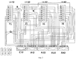
FIG. 1 is a diagram of electrical connections of a part of a device containing four primary removals and an input connecting plug or contact with groups of switches;
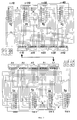
FIG. 2 is a diagram of the electrical connections of a part of a device containing four secondary plugs, an output connector or contact that can be connected to the specified input connector or contact, and a group of switches;
FIG. 3 is a summary diagram containing two wiring diagrams shown in FIG. 1 and 2, connected to each other by means of a connecting element.
Обращаясь к фиг. 1: имеется четыре первичных съема A1, A2, A3, A4 с восемью проводами, подключающимися к каждому из них (выполнены с формированием четырех дублетов, несущих эквивалентное число электрических сигналов), которые можно избирательно или обратимо подключать к соединительному элементу (штеккеру или контакту) C1 посредством четырех групп множественных переключателей SW1, SW2, SW3, SW4 с многофункциональными контактами, т.е. скомпонованными, например, таким образом, чтобы подключать различные соединительные провода в зависимости от их включенного (положение "On"), или выключенного (положение "Off") состояния. Turning to FIG. 1: there are four primary detectors A1, A2, A3, A4 with eight wires connected to each of them (made with the formation of four doublets carrying an equivalent number of electrical signals) that can be selectively or reversibly connected to a connecting element (plug or contact) C1 via four groups of multiple switches SW1, SW2, SW3, SW4 with multi-function contacts, i.e. arranged, for example, in such a way as to connect various connecting wires depending on their on (“On” position) or off (“Off” position) state.
Для этой цели можно использовать компоненты других типов, такие как переключатели и/или шунтирующие резисторы со скользящими контактами, или аналогичные устройства. For this purpose, other types of components can be used, such as switches and / or shunt resistors with sliding contacts, or similar devices.
В указанной фиг. 1, например, контактный вывод 1 входящего штеккера C1 можно избирательно или обратимо подключать к контакту 1 первичного съема A1, либо к контакту 4 первичного съема A2, или к контакту 3 последнего. Это осуществляют включением различным образом разных переключателей (8 на фиг. 1), образующих часть группы переключателей SW1. In said FIG. 1, for example, the
Аналогичную операцию можно подобным образом выполнять для всех остальных контактов первичных съемов, подключая их заданным образом к выводам на штеккере C1 посредством других групп переключателей SW2, SW3 и SW4. A similar operation can be similarly performed for all other contacts of the primary taps, connecting them in a predetermined manner to the terminals on plug C1 through other groups of switches SW2, SW3 and SW4.
Обращаясь к фиг. 2: эту же операцию можно осуществить подключением контактных выводов штеккера C12 в заданной последовательности к различным контактам на вторичных исходящих съемах A12, A22, A32, A42 избирательным включением переключателей, образующих группы переключателей SW12, SW22, SW32 и SW42. Turning to FIG. 2: the same operation can be carried out by connecting the contact terminals of the connector C12 in a given sequence to various contacts on the secondary outgoing terminals A12, A22, A32, A42 by selectively activating the switches forming the switch groups SW12, SW22, SW32 and SW42.
Например, подключение вывода 1 множественного штеккера C12 к контакту 4 вторичного съема A22 (подключение переключателя 2 группы SW12 и разъединение переключателей 1 и 3): тем самым контакт 4 посредством множественного штеккера C1 подключают к контакту 1 первичного съема A1 или к одному из контактов 3 или 4 первичного съема A2 - в зависимости от того, как это соединение было сконфигурировано в соответствии с предшествующим разделом описания. For example, connecting
Тем самым предложено соединительное устройство для коммутирования и приема сигналов; и это устройство является гибким в применении, экономичным по себестоимости, быстродействующим и легко приводимым в действие - так достигается указанная цель данного изобретения. Thus, a connecting device for switching and receiving signals; and this device is flexible in application, cost-effective, quick-acting and easily actuated - this is the stated purpose of the present invention.
Следовательно, выводы всех первичных и вторичных съемов можно, таким образом, использовать полностью. Therefore, the conclusions of all primary and secondary removals can thus be fully utilized.
Как указано выше, описанные выше переключатели можно заменять другими типами, например типами со скользящими контактами, либо шунтирующими резисторами, или переключателями на два направления, которые в большей степени подходят различным конструкционным требованиям. As indicated above, the switches described above can be replaced with other types, for example, types with sliding contacts, or shunt resistors, or two-way switches that are more suitable for different design requirements.
Фиг. 3 изображает полную схему электросоединений изложенного выше устройства, состоящего из двух частей, изображенных на фиг. 1 и 2, взаимно соединенных посредством пары "штеккер C1/съем C12". FIG. 3 depicts a complete electrical connection diagram of the above device, consisting of two parts, shown in FIG. 1 and 2, interconnected by a pair of plug C1 / plug C12.
Для формирования секций соединительного кабеля можно, разумеется, соответствующие штеккеры и съемы соединить или смонтировать иным образом, с различными проводами, соединяющими первичные или вторичные съемы. To form sections of the connecting cable, of course, the corresponding plugs and sockets can be connected or mounted in another way, with various wires connecting the primary or secondary sockets.
Claims (4)
Applications Claiming Priority (3)
| Application Number | Priority Date | Filing Date | Title |
|---|---|---|---|
| CH01221/95A CH690603A5 (en) | 1995-04-28 | 1995-04-28 | Connection device for the shunting of electrical signals. |
| CH1221/95-8 | 1995-04-28 | ||
| PCT/IB1996/000378 WO1996034432A1 (en) | 1995-04-28 | 1996-04-25 | Connection device for switching electrical signals |
Publications (2)
| Publication Number | Publication Date |
|---|---|
| RU97119638A RU97119638A (en) | 1999-10-27 |
| RU2145757C1 true RU2145757C1 (en) | 2000-02-20 |
Family
ID=4205332
Family Applications (1)
| Application Number | Title | Priority Date | Filing Date |
|---|---|---|---|
| RU97119638A RU2145757C1 (en) | 1995-04-28 | 1996-04-25 | Electric signal switching connector |
Country Status (10)
| Country | Link |
|---|---|
| US (1) | US5986356A (en) |
| EP (1) | EP0823140A1 (en) |
| JP (1) | JPH11504181A (en) |
| CN (1) | CN1183176A (en) |
| AU (1) | AU5285796A (en) |
| BR (1) | BR9608329A (en) |
| CA (1) | CA2217324A1 (en) |
| CH (1) | CH690603A5 (en) |
| RU (1) | RU2145757C1 (en) |
| WO (1) | WO1996034432A1 (en) |
Families Citing this family (3)
| Publication number | Priority date | Publication date | Assignee | Title |
|---|---|---|---|---|
| DE19828259A1 (en) * | 1998-06-25 | 1999-12-30 | Behr Gmbh & Co | Electric control circuit for motor vehicle heating or air conditioning system |
| JP3853307B2 (en) * | 2003-07-08 | 2006-12-06 | 株式会社興研 | Dry high-voltage load system apparatus and chain disconnection / arc discharge prevention method of the apparatus |
| FR2873240B1 (en) * | 2004-07-16 | 2009-02-13 | Attardi Pyrenelec Sarl Soc | MULTIFUNCTION ELECTRICAL CONNECTION HOUSING. |
Family Cites Families (8)
| Publication number | Priority date | Publication date | Assignee | Title |
|---|---|---|---|---|
| NL160111C (en) * | 1972-04-27 | 1979-09-17 | Philips Nv | SWITCH NETWORK EQUIPPED WITH A PRINT PLATE. |
| US4345251A (en) * | 1981-02-20 | 1982-08-17 | The United States Of America As Represented By The Secretary Of The Navy | Solid state commutator switch |
| JPS6048681U (en) * | 1983-09-09 | 1985-04-05 | 株式会社 テクノパ−ク峰 | Cable with switch |
| US4773867A (en) * | 1986-07-02 | 1988-09-27 | Amp Incorporated | Premise distribution cross connect apparatus |
| CA1297567C (en) * | 1987-02-06 | 1992-03-17 | Kazuo Hajikano | Self routing-switching system |
| US4907253A (en) * | 1988-09-07 | 1990-03-06 | Pacific Bell | Cross-connected switch having means for removing switching modules without interrupting service |
| FR2659819B1 (en) * | 1990-03-14 | 1992-05-29 | Alcatel Nv | SELF - ROUTING MULTI - PATH SWITCHING NETWORK FOR SWITCHING ASYNCHRONOUS MULTIPLEXED TIME CELLS. |
| US5361254A (en) * | 1991-12-20 | 1994-11-01 | Siemens Aktiengesellschaft | Switch mechanism for switching signals at inputs onto outputs and switching networks for interlinking first and second transmission media |
-
1995
- 1995-04-28 CH CH01221/95A patent/CH690603A5/en not_active IP Right Cessation
-
1996
- 1996-04-25 BR BR9608329A patent/BR9608329A/en not_active Application Discontinuation
- 1996-04-25 JP JP53232196A patent/JPH11504181A/en active Pending
- 1996-04-25 WO PCT/IB1996/000378 patent/WO1996034432A1/en not_active Application Discontinuation
- 1996-04-25 RU RU97119638A patent/RU2145757C1/en active
- 1996-04-25 CN CN96193557A patent/CN1183176A/en active Pending
- 1996-04-25 AU AU52857/96A patent/AU5285796A/en not_active Abandoned
- 1996-04-25 EP EP19960909307 patent/EP0823140A1/en not_active Withdrawn
- 1996-04-25 CA CA 2217324 patent/CA2217324A1/en not_active Abandoned
- 1996-04-25 US US08/945,027 patent/US5986356A/en not_active Expired - Fee Related
Also Published As
| Publication number | Publication date |
|---|---|
| CN1183176A (en) | 1998-05-27 |
| CA2217324A1 (en) | 1996-10-31 |
| WO1996034432A1 (en) | 1996-10-31 |
| US5986356A (en) | 1999-11-16 |
| EP0823140A1 (en) | 1998-02-11 |
| BR9608329A (en) | 1999-02-23 |
| CH690603A5 (en) | 2000-10-31 |
| AU5285796A (en) | 1996-11-18 |
| JPH11504181A (en) | 1999-04-06 |
Similar Documents
| Publication | Publication Date | Title |
|---|---|---|
| US5722862A (en) | Modular control apparatus having integrated field bus coupling | |
| US20100073483A1 (en) | System and method for transmitting video from multiple video cameras over a single multiple pair, twisted pair cable | |
| KR910000848B1 (en) | Modular plug connector | |
| ATE173359T1 (en) | SERIES CLAMP | |
| RU94026948A (en) | CROSS COMMUNICATION SYSTEMS FOR TELECOMMUNICATION SYSTEMS | |
| CA2142046A1 (en) | Watthour Meter Socket Adapter with Additional Plug-In Terminal Capability | |
| RU2145757C1 (en) | Electric signal switching connector | |
| JP2587316B2 (en) | Multi-pole electrical connector for coaxial flat cable | |
| US7059864B2 (en) | Distribution device of a telecommunications system | |
| US4970505A (en) | Three stage switching apparatus | |
| RU97119638A (en) | CONNECTING DEVICE FOR SWITCHING ELECTRICAL SIGNALS | |
| EP1012913B1 (en) | A set of devices for transferring electric signals | |
| EA199801021A2 (en) | A device for electrical connection of a differential unit to a circuit breaker | |
| US4089577A (en) | Distributing device for a multiconductor cable | |
| AU746424B2 (en) | A cabling testing device | |
| GB2022853A (en) | Identifying Conductors in Multi- Conductor Cables | |
| JP2524900B2 (en) | Signal processor | |
| AU2009100519A4 (en) | Electrical loom outlet | |
| JPH05242932A (en) | Pin plug | |
| KR0119155Y1 (en) | Board relay circuit | |
| TH2839B (en) | Standard plug-in power connector | |
| TH1103A (en) | Standard plug-in power connector | |
| JPS6489271A (en) | Connecting structure for electronic apparatus | |
| SE423658B (en) | Connection device for circuit card | |
| ATE119321T1 (en) | ARRANGEMENT FOR OPTIONALLY CONNECTING ELECTRICAL CABLES. |