RU2139503C1 - Gear measuring volumetric flow rate of fluid in nonramming conduit - Google Patents
Gear measuring volumetric flow rate of fluid in nonramming conduit Download PDFInfo
- Publication number
- RU2139503C1 RU2139503C1 RU98109270A RU98109270A RU2139503C1 RU 2139503 C1 RU2139503 C1 RU 2139503C1 RU 98109270 A RU98109270 A RU 98109270A RU 98109270 A RU98109270 A RU 98109270A RU 2139503 C1 RU2139503 C1 RU 2139503C1
- Authority
- RU
- Russia
- Prior art keywords
- meter
- fluid
- liquid
- flow rate
- output
- Prior art date
Links
Images

Landscapes
- Measuring Volume Flow (AREA)
Abstract
Description
Изобретение относится к приборостроению, а именно к области измерения объемного расхода жидкости в безнапорных каналах, например самоточных каналов сточных вод. The invention relates to instrumentation, and in particular to the field of measuring the volumetric flow rate of liquid in pressureless channels, for example, self-flowing sewage channels.
Известен ультразвуковой измеритель объемного расхода жидкости (см. патент РФ N 1806329, дата приоритета 11.09.90, 5 МКИ G 01 F 1/66), содержащий корпус, турбинку с устройством модуляции, излучатель и приемник ультразвукового сигнала, связанные с генератором, и счетчик импульсов. При этом корпус выполнен с выступающей камерой, в верхней части которой установлен излучатель ультразвукового сигнала, турбинка с устройством модуляции установлена в корпусе тангенциально, при этом ось вращения турбинки перпендикулярна оси излучателя ультразвукового сигнала и смещена относительно оси корпуса в сторону выступающей камеры, а приемник ультразвукового сигнала установлен на боковой стенке. Излучатель и приемник измерителя работают непосредственно в жидкой измеряемой среде. При этом измеритель неподвижно закрепляют в заданной точке поперечного сечения потока. A known ultrasonic liquid volumetric flow meter (see RF patent N 1806329, priority date 11.09.90, 5 MKI G 01 F 1/66), comprising a housing, a turbine with a modulation device, an emitter and an ultrasonic signal receiver associated with the generator, and a counter pulses. The housing is made with a protruding chamber, in the upper part of which an ultrasonic signal emitter is installed, a turbine with a modulation device is installed tangentially in the housing, while the axis of rotation of the turbine is perpendicular to the axis of the ultrasonic emitter and offset relative to the axis of the housing toward the protruding chamber, and the ultrasonic signal receiver mounted on the side wall. The emitter and receiver of the meter work directly in a liquid medium. In this case, the meter is fixedly fixed at a given point in the cross section of the flow.
Основным недостатком известного устройства является недостаточная точность измерения объемного расхода жидкости. The main disadvantage of the known device is the lack of accuracy in measuring the volumetric flow rate of the liquid.
Кроме того, при измерении объемного расхода необходимо погружать корпус прибора в контролируемый поток, что служит причиной относительно низкой надежности прибора при определении объемного расхода жидкости, содержащей инородные твердые и вязкие включения, которые могут вызвать разрушение турбинки, погруженной в контролируемую жидкость. In addition, when measuring the volumetric flow rate, it is necessary to immerse the casing of the device in a controlled flow, which causes a relatively low reliability of the device when determining the volumetric flow rate of a liquid containing foreign solid and viscous inclusions that can cause the destruction of a turbine immersed in a controlled liquid.
Из известных устройств наиболее близким по технической сущности и достигаемому результату к заявляемому изобретению является выбранный авторами за прототип расходомер для открытых каналов (см. патент Германии N 4016529, дата приоритета 07.11.91., 5 МКИ G 01 P 5/00), состоящий из блока измерения скорости жидкости, блока измерения уровня жидкости, блока позиционирования, блока вычислителя и индикатора. Для измерения объемного расхода необходимо погружение блока измерения скорости и блока измерения уровня жидкости в контролируемый поток. Of the known devices, the closest in technical essence and the achieved result to the claimed invention is a flowmeter for open channels selected by the authors for the prototype (see German patent N 4016529, priority date 07.11.91., 5 MKI G 01 P 5/00), consisting of a fluid velocity measuring unit, a fluid level measuring unit, a positioning unit, a calculator unit and an indicator. To measure the volumetric flow rate, it is necessary to immerse the speed measuring unit and the liquid level measuring unit in a controlled flow.
Расходомер содержит зонд, который может перемещаться в канале по двум ортогональным направлениям. The flow meter contains a probe that can move in the channel in two orthogonal directions.
В фазе калибровки зондом проводят измерения координатной сетки для определения профиля потока, при этом определяют коэффициент пересчета между скоростью в фиксированном опорном положении зонда и средней скоростью потока. In the probe calibration phase, the coordinate grid is measured to determine the flow profile, and the conversion factor between the speed in the fixed reference position of the probe and the average flow rate is determined.
В следующей фазе измерения определяют скорость потока в опорном фиксированном положении, а по ней с учетом коэффициента пересчета - фактическую общую скорость потока. In the next phase of measurement, the flow velocity is determined in the reference fixed position, and from it, taking into account the conversion factor, the actual total flow velocity.
Уровнемер измеряет уровень жидкости, который учитывается при расчете заданного потоком поперечного сечения канала в ЭВМ. The level gauge measures the liquid level, which is taken into account when calculating a given cross-section of the channel in a computer.
Фазу калибровки можно повторить с произвольной частотой, в частности, при изменяющемся уровне наполнения или при измерении поперечного сечения канала за счет отложений. The calibration phase can be repeated with an arbitrary frequency, in particular, with a changing filling level or when measuring the channel cross section due to deposits.
Расходомер для открытых каналов содержит зонд, погружаемый в жидкость и позволяющий измерять скорость потока. Зонд вмонтирован в позиционирующее устройство и управляется по положению и приводится в движение по команде от вычислителя. Зонд может быть перемещен в любую точку, лежащую в плоскости измерения, проходящей поперек канала, результаты измерения скорости потока запоминаются вычислителем. The flow meter for open channels contains a probe immersed in a liquid and allowing to measure the flow rate. The probe is mounted in a positioning device and is controlled by position and is driven by a command from the calculator. The probe can be moved to any point lying in the measurement plane extending across the channel, the results of the flow velocity measurement are stored by the calculator.
Вычислитель в фазе калибровки вырабатывает значения средней скорости потока Vm в точке измерения и относительную скорость потока в опорном положении.The calculator in the calibration phase produces the average flow velocity V m at the measurement point and the relative flow velocity in the reference position.
Вычислитель устанавливает зонд на опорную позицию в фазе измерения и вычисляет фактическую общую скорость потока на основе соотношения, построенного в фазе калибровки между средней скоростью потока Vm и относительной скоростью в опорном положении.The calculator sets the probe to the reference position in the measurement phase and calculates the actual total flow rate based on the relationship constructed in the calibration phase between the average flow velocity V m and the relative velocity in the reference position.
Расходомер характеризуется тем, что конструкцией предусматривается измеритель уровня, измеряющий высоту уровня в канале, показания которого используются для оценки заполненного жидкостью поперечного сечения канала, а тем самым и скорости потока. The flowmeter is characterized by the fact that the design provides a level meter that measures the height of the level in the channel, the readings of which are used to estimate the channel cross-section filled with liquid, and thereby the flow rate.
Расходомер характеризуется тем, что позиционирующее устройство, управляемое клавишным приспособлением, предусмотрено для "ощупывания" профиля канала. The flowmeter is characterized in that a positioning device controlled by a keyboard device is provided for “feeling” the channel profile.
Расходомер характеризуется тем, что вычислитель устанавливает любую выбранную позицию как опорную и, принимая во внимание процентное отклонение скорости потока в опорной точке от средней скорости потока Vm в фазе измерения, вычисляет фактическую общую скорость потока.The flowmeter is characterized in that the calculator sets any selected position as the reference and, taking into account the percentage deviation of the flow velocity at the reference point from the average flow velocity V m in the measurement phase, calculates the actual total flow velocity.
Расходомер характеризуется тем, что вычислитель как определитель опорной позиции устанавливает положение, которое располагается на линии потока и соответствует средней скорости потока Vm или определенному заранее заданному процентному отношению средней скорости.The flowmeter is characterized in that the calculator as a determinant of the reference position sets a position that is located on the flow line and corresponds to the average flow rate V m or a predetermined percentage of the average speed.
Способ измерения скорости взят из DEAS 1673453. Здесь звуковой сигнал принимается двумя приемниками, помещенными в поток жидкости. The speed measurement method is taken from DEAS 1673453. Here, an audio signal is received by two receivers placed in a liquid stream.
Расходомер позволяет проводить измерение интегральной скорости одним измерителем скорости жидкости, который по заданному закону перемещают от одного места измерения в контролируемом потоке жидкости к другому в плоскости поперечного сечения потока с помощью блока позиционирования. Тем самым проведение измерений возможно только при погружении измерителя в контролируемый поток. The flow meter allows you to measure the integral velocity with one liquid velocity meter, which according to a given law is moved from one measurement location in a controlled fluid flow to another in the plane of the cross section of the flow using a positioning unit. Thus, measurements are possible only when the meter is immersed in a controlled flow.
Основным преимуществом прототипа (см. патент Германии N 4016529) по сравнению с аналогом (см. патент РФ N 1806329) является получение более точных показаний, достигаемых измерением скорости потока жидкости в нескольких точках поперечного сечения измеряемого потока. The main advantage of the prototype (see German patent N 4016529) in comparison with the analogue (see RF patent N 1806329) is to obtain more accurate readings obtained by measuring the fluid flow rate at several points of the cross section of the measured flow.
Основным недостатком известного устройства по патенту Германии N 4016529 является то, что для измерения объемного расхода необходимо погружать корпус прибора в контролируемый поток, что служит причиной относительно низкой надежности прибора при определении объемного расхода жидкости с инородными твердыми и вязкими включениями. The main disadvantage of the known device according to German patent N 4016529 is that to measure the volumetric flow rate, it is necessary to immerse the body of the device in a controlled flow, which causes a relatively low reliability of the device when determining the volumetric flow rate of a liquid with foreign solid and viscous inclusions.
Перед заявляемым изобретением поставлена задача повышения надежности эксплуатации путем исключения непосредственного контакта расходомера с контролируемой жидкостью, что позволяет расширить виды контролируемой жидкости по химическому составу и загрязненности. The claimed invention has the task of increasing the reliability of operation by eliminating direct contact of the flowmeter with a controlled fluid, which allows to expand the types of controlled fluid in chemical composition and contamination.
Поставленная задача решается за счет того, что в устройстве для измерения объемного расхода жидкости в безнапорных каналах, содержащем измеритель скорости, измеритель уровня жидкости, вычислитель и индикатор, выход измерителя скорости и выход измерителя уровня жидкости соединены с соответствующими входами вычислителя, а выход вычислителя соединен со входом индикатора, согласно изобретению измеритель скорости выполнен в виде активного локационного датчика, что позволяет измерять скорость жидкости в открытом канале без погружения измерителя скорости в контролируемую жидкость. The problem is solved due to the fact that in the device for measuring the volumetric flow rate of liquid in pressureless channels containing a speed meter, a liquid level meter, a calculator and an indicator, the output of the speed meter and the output of the liquid level meter are connected to the corresponding inputs of the calculator, and the output of the calculator is connected to the indicator input, according to the invention, the speed meter is made in the form of an active location sensor, which allows you to measure the fluid velocity in an open channel without immersion speed meter into a controlled fluid.
При этом измеритель уровня жидкости также может быть выполнен в виде активного локационного датчика. In this case, the liquid level meter can also be made in the form of an active location sensor.
Измеритель скорости жидкости снабжен жестко связанным с его корпусом узлом регулирования диаграммы направленности. Диаграмму направленности формируют так, что она захватывает всю ширину поверхности измеряемого потока жидкости. Измерители скорости жидкости и уровня жидкости располагают над поверхностью измеряемой жидкости так, чтобы расстояние между поверхностной волной при максимально возможном уровне заполнения канала и измерителями скорости и уровня жидкости было не менее 0,5 метра. Ось диаграммы направленности измерителя скорости ориентируют под острым углом к вектору скорости измеряемого потока (по или против направления вектора скорости измеряемого потока) так, чтобы засвеченная излучением измерителя скорости область захватывала всю ширину канала. Именно такое регулирование диаграммы направленности измерителя скорости позволяет получать точное усредненное значение поверхностной скорости жидкости в безнапорном канале. Ось диаграммы направленности измерителя уровня жидкости формируют перпендикулярно зеркалу измеряемой жидкости. The liquid velocity meter is equipped with a radiation pattern regulation unit rigidly connected to its body. The radiation pattern is formed so that it captures the entire width of the surface of the measured fluid flow. The liquid velocity and liquid level meters are positioned above the surface of the measured liquid so that the distance between the surface wave at the maximum possible filling level of the channel and the velocity and liquid level meters is at least 0.5 meters. The axis of the radiation pattern of the speed meter is oriented at an acute angle to the velocity vector of the measured flow (in or against the direction of the velocity vector of the measured flow) so that the region illuminated by the radiation of the speed meter captures the entire channel width. It is such a regulation of the directional pattern of the speed meter that allows you to get the exact average value of the surface velocity of the liquid in the pressureless channel. The axis of the radiation pattern of the liquid level meter is formed perpendicular to the mirror of the measured liquid.
Измерение расхода производят в два этапа. Сначала измеряют скорость и уровень контролируемого потока. Интегральная поверхностная скорость измеряемой жидкости определяется доплеровским сдвигом излучаемых измерителем скорости и отраженных от поверхности жидкости частот с учетом угла наклона линии визирования к поверхности жидкости. Расстояние от измерителя уровня до поверхности жидкости определяется временным интервалом между излучением ультразвукового сигнала и регистрацией отраженного от поверхности жидкости эхосигнала. Зная расстояние от излучателя до дна канала, рассчитывают наполнение канала. Flow measurement is carried out in two stages. First measure the speed and level of controlled flow. The integral surface velocity of the measured liquid is determined by the Doppler shift of the frequencies emitted by the speed meter and reflected from the surface of the liquid, taking into account the angle of inclination of the line of sight to the surface of the liquid. The distance from the level meter to the liquid surface is determined by the time interval between the emission of the ultrasonic signal and the registration of the echo signal reflected from the liquid surface. Knowing the distance from the emitter to the bottom of the channel, calculate the filling of the channel.
Пересчет уровня и скорости в расход осуществляется по специально разработанной формуле (см. например Курганов А.М., Федоров Н.Ф. Гидравлические расчеты систем водоснабжения и водоотведения. Справочник. Л.: Стройиздат, 1986. Федоров Н.Ф. Новые исследования и гидравлические расчеты канализационных сетей. Л.: Стройиздат, 1964). Recalculation of the level and speed in the flow rate is carried out according to a specially developed formula (see, for example, Kurganov A.M., Fedorov N.F. Hydraulic calculations of water supply and sanitation systems. Reference book. L .: Stroyizdat, 1986. Fedorov N.F. New studies and hydraulic calculations of sewer networks. L .: Stroyizdat, 1964).
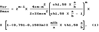
где m - коэффициент расхода водослива;
а и b - параметры лотка.
where m is the coefficient of discharge of the spillway;
a and b are the tray options.
Заявляемое изобретение позволяет получить технический результат, а именно позволяет измерять объемный расход жидкости без погружения измерителей в контролируемую среду, что позволяет повысить надежность и долговечность прибора. The claimed invention allows to obtain a technical result, namely, it allows to measure the volumetric flow rate of the liquid without immersing the meters in a controlled environment, which improves the reliability and durability of the device.
Кроме этого заявляемое изобретение также позволяет определять объемный расход жидкости за одно измерение уровня и поверхностной скорости, что увеличивает быстродействие по сравнению с прототипом (см. патент Германии N 4016529) на величину
(Nгор•Nверт-1)•t
где Nверт - количество зондируемых прототипом плоскостей сечения потока жидкости, параллельных ее зеркалу;
Nгор - количество зондируемых прототипом точек на каждой из плоскостей Nверт;
t - время одного измерения.In addition, the claimed invention also allows you to determine the volumetric flow rate of the fluid in one measurement of the level and surface speed, which increases the speed compared to the prototype (see German patent N 4016529) by
(N mountains • N vert -1) • t
where N vert - the number of probed by the prototype planes of the cross section of the fluid flow parallel to its mirror;
N mountains - the number of probed by the prototype points on each of the planes N vert ;
t is the time of one measurement.
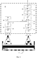
На фиг. 1 приведена структурная схема устройства для измерения объемного расхода жидкости в безнапорном канале. In FIG. 1 shows a structural diagram of a device for measuring the volumetric flow rate of a liquid in a pressureless channel.
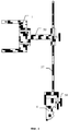
На фиг. 2 приведена структурная схема измерителя скорости жидкости. In FIG. 2 shows a block diagram of a liquid velocity meter.
На фиг. 3 приведена структурная схема измерителя уровня жидкости. In FIG. 3 shows a block diagram of a liquid level meter.
На фиг. 4 приведена структурная схема узла ориентации диаграммы направленности. In FIG. 4 is a structural diagram of an orientation pattern orientation unit.
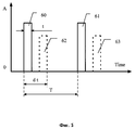
На фиг. 5 приведен график, иллюстрирующий работу измерителя уровня жидкости. In FIG. 5 is a graph illustrating the operation of a liquid level meter.
Заявляемое устройство для измерения объемного расхода жидкости в безнапорном канале, состоит из измерителя 1 скорости жидкости 2 (фиг. 1), измерителя 3 уровня жидкости 2 в открытом канале 4, вычислителя 5 и индикатора 6, причем выходы 7 и 8 соответственно измерителя 1 скорости и измерителя 3 уровня жидкости 2 соединены с соответствующими входами 9 и 10 вычислителя 5, выход 11 которого соединен со входом 12 индикатора 6. The inventive device for measuring the volumetric flow rate of fluid in the pressureless channel, consists of a
Измеритель 1 скорости выполнен в виде активного локационного датчика, включает пьезокерамический преобразователь (излучатель) 13 и пьезокерамический преобразователь (приемник излучения) 14, которые имеют диаграммы направленности 15 и 16 соответственно, и снабжен жестко связанным с его корпусом узлом 17 регулирования диаграмм 15 и 16 направленности. Измеритель 3 уровня жидкости 2 включает пьезокерамический преобразователь 18, который имеет диаграмму 19 направленности. The
Именно эта совокупность блоков и их соединений в измерителе объемного расхода жидкости в безнапорных каналах позволяет решить поставленную задачу, а именно измерять объемный расход жидкости без погружения измерителей в контролируемую среду, что позволяет повысить надежность и долговечность прибора. It is this set of blocks and their connections in the meter of the volumetric flow rate of liquid in the pressureless channels that allows us to solve the problem, namely, to measure the volumetric flow rate of the liquid without immersing the meters in a controlled environment, which improves the reliability and durability of the device.
Измеритель 1 скорости жидкости 2 (фиг. 2) изготовлен по активной локационной схеме. Измеритель 1 состоит из пьезокерамических преобразователей 13 и 14, которые имеют диаграммы направленности 15 и 16 соответственно, генератора 20, усилителя 21, пьезокерамических преобразователей 13 и 14, предварительного усилителя 22, смесителя 23, фильтра нижних частот 24, схемы предварительной фильтрации 25. The liquid velocity meter 1 (Fig. 2) is made according to the active location scheme. The
Выход 26 генератора 20 подключен ко входу 27 усилителя 21 и входу 28 смесителя 23. Выход 29 усилителя 21 подключен ко входу 30 пьезокерамического преобразователя 13, с помощью которого формируют диаграмму направленности 15. Выход 31 пьезокерамического преобразователя 14 подключен ко входу 32 предварительного усилителя 22. Выход 33 предварительного усилителя 22 подключен ко входу 34 смесителя 23. Выход 35 смесителя 23 подключен ко входу 36 фильтра нижних частот 24. Выход 37 фильтра нижних частот 24 подключен ко входу 38 схемы предварительной фильтрации 25. Выход 7 схемы предварительной фильтрации 25 является выходом измерителя 1 скорости жидкости 2. Выход 7 подключен к входу 9 вычислителя 5. The
Измеритель 3 уровня (фиг. 3) изготовлен по активной локационной схеме. Измеритель 3 уровня состоит из пьезокерамического преобразователя 18, генератора 39, усилителя 40, электронного узла 41, схемы учета температуры 42, преобразователя 43.
Вход 44 пьезокерамического преобразователя 18 подключен к выходу 45 генератора 39, выход 46 пьезокерамического преобразователя 18 подключен к входу 47 усилителя 40. Выход 48 усилителя 40 подключен к входу 49 электронного узла 41, к входу 50 которого подключен выход 45 генератора 39. Выход 51 электронного узла 41 подключен к входу 52 преобразователя 43, к входу 53 которого подключен выход 54 схемы учета температуры 42, выход 55 преобразователя 43 подключен к входу 56 генератора 39, выход 8 преобразователя 43 является выходом измерителя уровня 3. Выход 8 подключен к входу 10 вычислителя 5 (фиг. 1). The
Вычислитель 5 (фиг. 1) состоит из системного блока IBM-PC с программным обеспечением для организации управления проведения измерений. Calculator 5 (Fig. 1) consists of an IBM-PC system unit with software for organizing measurement control.
Выход 11 вычислителя 5 подключен к входу 12 индикатора 6. К входу 9 вычислителя 5 подключен выход 7 измерителя скорости 1, к входу 10 вычислителя 5 подключен выход 8 измерителя 3 уровня. The output 11 of the calculator 5 is connected to the input 12 of the indicator 6. To the input 9 of the calculator 5 is connected the
Индикатор 6 состоит из совместимого с вычислителем 5 монитора. Вход 12 индикатора 6 подключен к выходу 11 вычислителя 5. Indicator 6 consists of a monitor compatible with calculator 5. Input 12 of indicator 6 is connected to output 11 of calculator 5.
Узел регулирования диаграммы направленности 17 (фиг. 4) состоит из штатива 57, зажима 58, фиксирующей насадки 59. The site of regulation of the radiation pattern 17 (Fig. 4) consists of a
Штатив 57 жестко закреплен к стенке канала 4 зажимом 58. Измеритель скорости 1 неподвижно закреплен на фиксирующей насадке 59. Фиксирующая насадка 59 неподвижно закреплена на штативе 57 так, что диаграммы направленности 15 и 16 захватывают всю ширину канала 4 с жидкостью 2. The
Проводились испытания опытного образца заявляемого устройства. Tests of a prototype of the claimed device.
Активный локационный измеритель 1 скорости жидкости 2 имеет следующие технические характеристики:
- диапазон измерения поверхностной скорости от 0.2 до 7 м/с;
- погрешность измерения поверхностной скорости (от измеренной величины) не более 5%;
- влажность окружающей среды до 100%;
- температура окружающей среды от +5 до +40oC;
- переменный газовый состав среды.
- measuring range of surface velocity from 0.2 to 7 m / s;
- the error in measuring the surface velocity (of the measured value) is not more than 5%;
- environmental humidity up to 100%;
- ambient temperature from +5 to +40 o C;
- variable gas composition of the medium.
Активный локационный измеритель 3 уровня жидкости 2 имеет следующие технические характеристики:
- диапазон измерения уровня от 1.5 до 25 м;
- погрешность измерения уровня (от измеренной величины) не более 1%,
- влажность окружающей среды до 100%;
- температура окружающей среды от +5 до +40oC;
- переменный газовый состав среды.The
- range of level measurement from 1.5 to 25 m;
- the error of level measurement (of the measured value) is not more than 1%,
- environmental humidity up to 100%;
- ambient temperature from +5 to +40 o C;
- variable gas composition of the medium.
Измеритель 1 скорости жидкости 2 построен на основе использования доплеровского сдвига. The
При помощи генератора 20 вырабатывают электрический сигнал, представляющий собой колебания ультразвуковой частоты. С выхода 26 генератора 20 на вход 27 усилителя мощности 21 подают пачки электрических колебаний ультразвуковой частоты длительностью t при периоде повторения пачек T. Этот электрический сигнал усиливают усилителем мощности 21 и подают на ультразвуковой пьезокерамический преобразователь 13. Здесь происходит преобразование электрических колебаний в акустический сигнал той же частоты. Using the
Акустический зондирующий сигнал контактирует с поверхностью потока жидкости 2. Если поверхность имеет "шероховатость", т.е. пузырьки воздуха либо инородные включения, движущиеся со скоростью потока верхнего слоя, то отраженный акустический сигнал имеет доплеровский сдвиг частоты, несущий информацию о скорости перемещения поверхностного слоя жидкости 2. The acoustic probe signal is in contact with the surface of the fluid flow 2. If the surface has a “roughness”, i.e. air bubbles or foreign inclusions moving with the flow rate of the upper layer, the reflected acoustic signal has a Doppler frequency shift that carries information about the speed of movement of the surface layer of the liquid 2.
Такой акустический эхо-сигнал воспринимают при помощи пьезокерамического приемника 16 и преобразуют в электрический. Электрический сигнал, как и акустический, содержит доплеровский сдвиг частоты, пропорциональный измеряемой скорости поверхностного слоя жидкости. Such an acoustic echo signal is sensed using a
С выхода пьезокерамического преобразователя (приемника) 14 сигнал подают на предварительный усилитель 22, а с его выхода 33 на вход 34 смесителя 23. На вход 28 смесителя 23 подают сигнал с выхода 26 генератора 20. В смесителе 23 осуществляют перемноженное зондирующего и отраженного от поверхности жидкости 2 сигналов. В результате перемноженная на выходе 35 наблюдают сигнал разности частот зондирующего и отраженного сигналов, а также и их суммы. Этот сигнал подают на фильтр нижних частот 24, где осуществляют ослабление компоненты сигнала суммарной частоты. Тем самым на выходе 37 фильтра 24 наблюдают сигнал, частота которого пропорциональна измеряемой скорости поверхностного слоя жидкости 2. С выхода 37 фильтра 24 сигнал подают на схему предварительной фильтрации 25, в состав которой включен компаратор уровня. Подбор его уровня срабатывания позволяет подавлять шумы, сопровождающие всю рассматриваемую процедуру формирования сигнала. В результате обработки на выходе 7 схемы 25 наблюдаются прямоугольные импульсы, "очищенные" от "дребезга". Эти импульсы, число которых в единицу времени соответствует измеряемой скорости, подают на вход 9 вычислителя 5. From the output of the piezoceramic transducer (receiver) 14, the signal is supplied to the
Процедура обработки информации, осуществляемая вычислителем 5, кроме подсчета числа импульсов в единицу времени содержит также операции логической фильтрации результатов измерений. Учитывается также и угол падения ультразвукового пучка на водную поверхность (Q), то есть угол между вертикалью к поверхности потока жидкости 2 и измерительной осью, являющейся центром зондирующего потока. The information processing procedure carried out by the calculator 5, in addition to counting the number of pulses per unit time also contains logical filtering operations of the measurement results. The angle of incidence of the ultrasonic beam on the water surface (Q) is also taken into account, that is, the angle between the vertical to the surface of the liquid flow 2 and the measuring axis, which is the center of the probe flow.
Доплеровский сдвиг частоты (Fдопл) принятого рассеянного поверхностью потока сигнала, то есть разность частот излученного (Fизл) и принятого сигналов в каждом из каналов этой схемы равна
Fдопл=2•Vжидк•Fизл•sin(Q)/C (3)
где C - скорость звука, Vжидк - скорость жидкости.The Doppler frequency shift (F dop ) of the received signal scattered by the surface of the signal stream, that is, the frequency difference of the emitted (F em ) and received signals in each channel of this circuit is
Swim F = 2 • V liq rad • F • sin (Q) / C (3)
where C is the speed of sound, V fluid is the speed of fluid.
Решив уравнение (3) относительно Vжидк, получим
Vжидк=C•Fдопл/(2•Fизл•sin(Q))= Fдопл/K (4)
где K - постоянный коэффициент.Solving equation (3) with respect to V fluid , we obtain
V liq = C • F swim / (2 • F rad • sin (Q)) = F swim / K (4)
where K is a constant coefficient.
Таким образом, введение в состав устройства для измерения объемного расхода жидкости в безнапорном канале устройства регулирования диаграммы направленности, жестко связанным с активным локационным измерителем поверхностной скорости, позволяет повысить надежность и расширить область применения расходомера по сравнению с известными аналогичными измерителями. Thus, the introduction to the composition of the device for measuring the volumetric flow rate of the liquid in the pressureless channel of the radiation pattern control device, rigidly connected to the active location-based surface velocity meter, allows to increase the reliability and expand the scope of the flow meter in comparison with the known similar meters.
Измерение расстояний с помощью акустических волн основано на свойстве их распространения в среде с конечной скоростью и по кратчайшему пути. При этом длина измеряемого отрезка L отождествляется с путем, который проходят волны от одного конца отрезка до другого. Предполагается, что упругие колебания распространяются прямолинейно и с постоянной для данного момента времени и на всем пути скоростью C. Если измерено время распространения акустических волн t, то расстояние может быть получено из уравнения равномерного прямолинейного движения
L=C•t (5)
Современные ультразвуковые дальномеры строятся на основе элементов цифровой техники. Эквивалентом измеряемого расстояния в таких приборах является число N импульсов частоты f (периода T=1/f), заносимых в счетчик за время задержки t акустического сигнала на измеряемом отрезке пути. Это число в режиме эхолокации определяется следующим образом:
N=[t/T]=[f•t]=[f•3•L/C]=[K•L] (6)
Такие технические средства измерения времени распространения акустических волн не накладывают ограничений на точность измерения расстояний, и достигнутые точностные показатели измерения расстояния будут определяться точностью измерения скорости распространения акустических волн. Скорость распространения звука в воздухе меняется во времени в связи с изменением состояния окружающей среды, что приводит к ошибкам измерения расстояний. Ниже приведены предельные ошибки, вызванные каждым из дестабилизирующих факторов:
- погрешность, обусловленная изменением температуры в диапазоне ±50oC, равна ±8%;
- максимальная относительная погрешность, вызванная ветром при эхолокации, равна отношению квадратов скоростей ветра и звука;
- максимальная погрешность, обусловленная изменением параметров воздуха, влажности (0,5%), газового состава (0,1%), давления (около 3•10-6%).The measurement of distances using acoustic waves is based on the property of their propagation in the medium with a finite speed and the shortest path. The length of the measured segment L is identified with the path that the waves travel from one end of the segment to the other. It is assumed that elastic vibrations propagate rectilinearly and at a constant speed C. For the propagation time of acoustic waves t, the distance can be obtained from the equation of uniform rectilinear motion
L = C • t (5)
Modern ultrasonic rangefinders are based on the elements of digital technology. The equivalent of the measured distance in such devices is the number N of frequency pulses f (period T = 1 / f), recorded in the counter during the delay time t of the acoustic signal on the measured path segment. This number in echolocation mode is determined as follows:
N = [t / T] = [f • t] = [f • 3 • L / C] = [K • L] (6)
Such technical means of measuring the propagation time of acoustic waves do not impose restrictions on the accuracy of measuring distances, and the achieved accuracy indicators of distance measurement will be determined by the accuracy of measuring the speed of propagation of acoustic waves. The speed of sound propagation in air varies over time due to changes in the state of the environment, which leads to errors in measuring distances. The following are marginal errors caused by each of the destabilizing factors:
- the error due to temperature changes in the range of ± 50 o C is equal to ± 8%;
- the maximum relative error caused by the wind during echolocation is equal to the ratio of the squares of the wind speeds and sound;
- the maximum error due to changes in the parameters of air, humidity (0.5%), gas composition (0.1%), pressure (about 3 • 10 -6 %).
Наиболее эффективным является способ компенсации влияния непостоянства скорости распространения акустических волн на точность измерений, основанный на непосредственном измерении скорости звука акустическим методом. Такой способ позволяет в реальном масштабе времени учитывать изменения скорости независимо от того, каким фактором эти изменения вызваны. The most effective is a method of compensating for the influence of inconstancy of the propagation speed of acoustic waves on the measurement accuracy, based on direct measurement of the speed of sound by the acoustic method. This method allows real-time accounting for changes in speed regardless of what factor these changes are caused by.
В состав измерителя 3 уровня входит генератор 39 электрических колебаний, который может функционировать либо автономно, либо в режиме управления от специального преобразователя 43. В автономном режиме с помощью генератора 39 вырабатывают электрические сигналы 60, 61 (фиг. 5), представляющие собой пачки колебаний ультразвуковой частоты с длительностью t и периодом следования T. В управляемом режиме параметры электрических сигналов: частота колебаний, длительность пачек и период их повторения изменяются вычислителем 43. The
В акустическом преобразователе 18 производят преобразование электрических сигналов в акустические ультразвуковые колебания, которые направляются в сторону зондируемой поверхности жидкости 2. In the
От зондируемой поверхность жидкости 2 отражают эхо-сигналы, которые принимают тем же акустическим преобразователем 18 и преобразуют в электрические сигналы 62, 63, похожие по форме на зондирующие, но сдвинутые во времени на величину dt и имеющие меньшую амплитуду, как показано на фиг. 5. Очевидно, что dt пропорционально расстоянию до зондирующей поверхности, т.е. измеряемому уровню жидкости. From the sensed surface of the liquid 2, echo signals are reflected, which are received by the same
Эхо-сигнал в электрической форме усиливают усилителем 40 и подают на вход 52 электронного узла 41, на второй вход 50 которого подают зондирующий сигнал с выхода 45 генератора 39. В электронном узле 41 формируют прямоугольные электрические импульсы с длительностью dt и периодом повторения Т. Тем самым мерой измеренного уровня является длительность импульса dt. Эти импульсы подают на вход преобразователя 43. Здесь сигнал фильтруют, в результате чего на выходе преобразователя 8 формируют сигнал уровня, представленный в двоичной форме. The echo signal in electrical form is amplified by an
Формирование достоверного уровня сопряжено с определенными трудностями. Они обусловлены зависимостью скорости распространения звука в среде от температуры, влажности воздуха, ветрового возмущения среды, нелинейностями тракта "генератор 39 - преобразователь 43" и шумами этого тракта при больших измеряемых дальностях. The formation of a reliable level is associated with certain difficulties. They are caused by the dependence of the speed of sound propagation in the medium on temperature, air humidity, wind disturbance of the medium, non-linearities of the “generator 39 -
Эти факторы учитывают в преобразователе 43, что позволяет минимизировать ошибки измерения. С этой целью используют датчик температуры, с помощью которого вырабатывают электрический сигнал, пропорциональный температуре. Этот сигнал преобразуют схемой учета температуры 42 и подают на вход 53 преобразователя 43, где он и используется при обработке результатов измерения уровня. С этой же целью, как было сказано выше, с помощью преобразователя 43 управляют параметрами зондирующих сигналов через генератор 39. These factors are taken into account in the
Сигналы с выхода преобразователя 43 подают на вычислитель 5 и индикатор 6. Кроме этого вычислитель 5 предусматривает возможность сопряжения с традиционными промышленными регистрирующими приборами. The signals from the output of the
Таким образом, именно то, что измеритель скорости выполнен в виде активного локационного датчика; измеритель уровня жидкости также может быть выполнен в виде активного локационного датчика; измеритель скорости жидкости снабжен жестко связанным с его корпусом узлом регулирования диаграммы направленности, которую формируют так, что она захватывает всю ширину поверхности измеряемого потока жидкости, заявляемое изобретение позволяет получить технический результат, а именно позволяет измерять объемный расход жидкости без погружения измерителей в контролируемую среду, что позволяет повысить надежность и долговечность прибора. Thus, it is precisely that the speed meter is made in the form of an active location sensor; the liquid level meter can also be made in the form of an active location sensor; the fluid velocity meter is equipped with a radiation pattern regulation unit rigidly connected to its body, which is formed so that it captures the entire width of the surface of the measured fluid flow, the claimed invention allows to obtain a technical result, namely, allows to measure the volumetric flow rate of the fluid without immersing the meters in a controlled environment, which improves the reliability and durability of the device.
Claims (2)
Priority Applications (1)
| Application Number | Priority Date | Filing Date | Title |
|---|---|---|---|
| RU98109270A RU2139503C1 (en) | 1998-04-29 | 1998-04-29 | Gear measuring volumetric flow rate of fluid in nonramming conduit |
Applications Claiming Priority (1)
| Application Number | Priority Date | Filing Date | Title |
|---|---|---|---|
| RU98109270A RU2139503C1 (en) | 1998-04-29 | 1998-04-29 | Gear measuring volumetric flow rate of fluid in nonramming conduit |
Publications (1)
| Publication Number | Publication Date |
|---|---|
| RU2139503C1 true RU2139503C1 (en) | 1999-10-10 |
Family
ID=20206051
Family Applications (1)
| Application Number | Title | Priority Date | Filing Date |
|---|---|---|---|
| RU98109270A RU2139503C1 (en) | 1998-04-29 | 1998-04-29 | Gear measuring volumetric flow rate of fluid in nonramming conduit |
Country Status (1)
| Country | Link |
|---|---|
| RU (1) | RU2139503C1 (en) |
Cited By (2)
| Publication number | Priority date | Publication date | Assignee | Title |
|---|---|---|---|---|
| RU2319933C2 (en) * | 2006-03-29 | 2008-03-20 | Государственное образовательное учреждение высшего профессионального образования Самарский государственный технический университет | Measuring instrument of the volume of liquid transported along the pipeline |
| RU2547877C1 (en) * | 2013-11-19 | 2015-04-10 | Анатолий Георгиевич Малюга | Method for determining volume of consumed liquid |
Citations (7)
| Publication number | Priority date | Publication date | Assignee | Title |
|---|---|---|---|---|
| US3974692A (en) * | 1973-08-16 | 1976-08-17 | Siemens Aktiengesellschaft | Apparatus for the measurement of the velocity of media flowing in conduits |
| FR2514130A1 (en) * | 1981-10-06 | 1983-04-08 | Elmar Medical Systems Ltd | ULTRASOUND FLUID LEVEL AND FLOW DETECTOR |
| DE3333409A1 (en) * | 1983-09-15 | 1985-04-04 | Siemens AG, 1000 Berlin und 8000 München | METHOD FOR ULTRASONIC FLOW MEASUREMENT ACCORDING TO THE DOPPLER PRINCIPLE WITH IMPROVED LOCAL RESOLUTION |
| FR2562242A1 (en) * | 1984-03-27 | 1985-10-04 | Micro Pure Systems Inc | Method and device for identifying discontinuities in a flow by an ultrasound technique |
| SU1506278A1 (en) * | 1987-01-04 | 1989-09-07 | Государственный гидрологический институт | Method of measuring water flow in river |
| RU2014567C1 (en) * | 1991-09-18 | 1994-06-15 | Исмаилов Мурад Марифович | Method of measuring flow rate of liquid and gas by doppler flowmeter |
| RU2104499C1 (en) * | 1996-03-01 | 1998-02-10 | Олег Константинович Лебедев | Process measuring flowrate of oil and oil products |
-
1998
- 1998-04-29 RU RU98109270A patent/RU2139503C1/en not_active IP Right Cessation
Patent Citations (7)
| Publication number | Priority date | Publication date | Assignee | Title |
|---|---|---|---|---|
| US3974692A (en) * | 1973-08-16 | 1976-08-17 | Siemens Aktiengesellschaft | Apparatus for the measurement of the velocity of media flowing in conduits |
| FR2514130A1 (en) * | 1981-10-06 | 1983-04-08 | Elmar Medical Systems Ltd | ULTRASOUND FLUID LEVEL AND FLOW DETECTOR |
| DE3333409A1 (en) * | 1983-09-15 | 1985-04-04 | Siemens AG, 1000 Berlin und 8000 München | METHOD FOR ULTRASONIC FLOW MEASUREMENT ACCORDING TO THE DOPPLER PRINCIPLE WITH IMPROVED LOCAL RESOLUTION |
| FR2562242A1 (en) * | 1984-03-27 | 1985-10-04 | Micro Pure Systems Inc | Method and device for identifying discontinuities in a flow by an ultrasound technique |
| SU1506278A1 (en) * | 1987-01-04 | 1989-09-07 | Государственный гидрологический институт | Method of measuring water flow in river |
| RU2014567C1 (en) * | 1991-09-18 | 1994-06-15 | Исмаилов Мурад Марифович | Method of measuring flow rate of liquid and gas by doppler flowmeter |
| RU2104499C1 (en) * | 1996-03-01 | 1998-02-10 | Олег Константинович Лебедев | Process measuring flowrate of oil and oil products |
Cited By (2)
| Publication number | Priority date | Publication date | Assignee | Title |
|---|---|---|---|---|
| RU2319933C2 (en) * | 2006-03-29 | 2008-03-20 | Государственное образовательное учреждение высшего профессионального образования Самарский государственный технический университет | Measuring instrument of the volume of liquid transported along the pipeline |
| RU2547877C1 (en) * | 2013-11-19 | 2015-04-10 | Анатолий Георгиевич Малюга | Method for determining volume of consumed liquid |
Similar Documents
| Publication | Publication Date | Title |
|---|---|---|
| CN114088151B (en) | External clip-on multi-channel ultrasonic flow detection device and detection method | |
| KR960013251B1 (en) | Ultrasonic Flow Measurement Method and Device | |
| US5777892A (en) | Doppler shift velocity measuring system with correction factors | |
| US6209388B1 (en) | Ultrasonic 2-phase flow apparatus and method | |
| RU2194949C2 (en) | Method of measuring average horizontal speed of river current | |
| US6901812B2 (en) | Single-body dual-chip Orthogonal sensing transit-time flow device | |
| WO1988008516A1 (en) | Ultrasonic fluid flowmeter | |
| US11619528B2 (en) | Ultrasonic flow measuring device having a wall thickness being less in the area of the phased array ultrasonic transducer contact area | |
| US7318355B2 (en) | Ultrasonic flow velocity meter and ultrasonic transducer thereof | |
| US10718646B2 (en) | Ultrasound flow measurement apparatus and method for determining the flow rate | |
| KR101195438B1 (en) | Ultrasonic flowmeter and method of measuring flux by ultrasonic waves | |
| JP2007529725A (en) | Ultrasonic flow rate flow sensor with transducer array and reflective surface | |
| RU2139503C1 (en) | Gear measuring volumetric flow rate of fluid in nonramming conduit | |
| US6854339B2 (en) | Single-body dual-chip orthogonal sensing transit-time flow device using a parabolic reflecting surface | |
| KR20180016116A (en) | Ultrasonic Flow Meter and Method for Flow Speed Measuring | |
| JPS6246812B2 (en) | ||
| JPH0688738A (en) | Ultrasonic wave flowmeter | |
| JP2009270882A (en) | Ultrasonic flowmeter | |
| KR100482226B1 (en) | Method and apparatus for measuring the amount of flowing in gas pipe using sonic waves | |
| KR19990004179A (en) | Vertical average flow rate measuring device for open channel | |
| RU2478917C2 (en) | Fluid medium flow metre in free-flow pipelines | |
| RU2069314C1 (en) | Method of measurement of flow rate of liquids with variable level and liquid flowmeter | |
| RU53001U1 (en) | ELECTRONIC-ACOUSTIC LIQUID MEASUREMENT DEVICE | |
| RU1140571C (en) | Method of measuring power of low-frequency hydroacoustic irradiator with internal air cavity | |
| RU2091716C1 (en) | Vortex flow meter |
Legal Events
| Date | Code | Title | Description |
|---|---|---|---|
| MM4A | The patent is invalid due to non-payment of fees |
Effective date: 20090430 |