RU2139490C1 - Method for blasting near guarded objects - Google Patents
Method for blasting near guarded objects Download PDFInfo
- Publication number
- RU2139490C1 RU2139490C1 RU98106881A RU98106881A RU2139490C1 RU 2139490 C1 RU2139490 C1 RU 2139490C1 RU 98106881 A RU98106881 A RU 98106881A RU 98106881 A RU98106881 A RU 98106881A RU 2139490 C1 RU2139490 C1 RU 2139490C1
- Authority
- RU
- Russia
- Prior art keywords
- charges
- wells
- holes
- blast
- area
- Prior art date
Links
- 238000005422 blasting Methods 0.000 title claims abstract description 22
- 238000000034 method Methods 0.000 title claims abstract description 18
- 238000005553 drilling Methods 0.000 claims abstract description 20
- 239000002360 explosive Substances 0.000 claims abstract description 18
- 230000000694 effects Effects 0.000 claims abstract description 5
- 238000011068 loading method Methods 0.000 claims description 4
- 239000006185 dispersion Substances 0.000 claims description 3
- 238000005065 mining Methods 0.000 abstract description 4
- 238000010276 construction Methods 0.000 abstract description 3
- 239000011435 rock Substances 0.000 abstract description 3
- 239000004567 concrete Substances 0.000 abstract description 2
- 230000007246 mechanism Effects 0.000 abstract description 2
- 238000010327 methods by industry Methods 0.000 abstract 1
- 239000000126 substance Substances 0.000 abstract 1
- 238000004880 explosion Methods 0.000 description 15
- 238000005516 engineering process Methods 0.000 description 3
- 238000004519 manufacturing process Methods 0.000 description 3
- 239000011150 reinforced concrete Substances 0.000 description 3
- 241000566515 Nedra Species 0.000 description 2
- 238000006073 displacement reaction Methods 0.000 description 2
- 239000002689 soil Substances 0.000 description 2
- 230000015572 biosynthetic process Effects 0.000 description 1
- 239000011449 brick Substances 0.000 description 1
- 230000006866 deterioration Effects 0.000 description 1
- 238000005474 detonation Methods 0.000 description 1
- 238000010586 diagram Methods 0.000 description 1
- 239000002184 metal Substances 0.000 description 1
- 230000001105 regulatory effect Effects 0.000 description 1
- 238000005303 weighing Methods 0.000 description 1
Images
Landscapes
- Drilling And Exploitation, And Mining Machines And Methods (AREA)
- Geophysics And Detection Of Objects (AREA)
Abstract
Description
Изобретение относится к области горного дела, строительства и может быть использовано при взрывной разработке среды (грунта, бетона и др.) вблизи охраняемых объектов (OO) - зданий, сооружений, механизмов, бортов выемок и т.д. The invention relates to the field of mining, construction and can be used in the explosive development of the environment (soil, concrete, etc.) near the protected objects (OO) - buildings, structures, mechanisms, sides of the recesses, etc.
Известен способ взрывания вблизи охраняемых объектов, включающий бурение рядов скважин с коэффициентом сближения, равным единице, заряжения их, деление массива на симметричные части, соединение зарядов магистралью взрывной сети и взрывание зарядов с замедлением (см. Нормативный справочник по буровзрывным работам. -М.: Недра, 1986, с. 30- 79). There is a known method of blasting near guarded objects, including drilling rows of wells with a convergence coefficient of unity, charging them, dividing the array into symmetrical parts, connecting charges to the blast network and blasting charges with delay (see. Normative guide on drilling and blasting operations. -M .: Nedra, 1986, pp. 30-79).
Недостатком этого способа является низкая эффективность обеспечения заданного комплекса технологических требований к взрывной разработке и отсутствие возможности согласования технологии с требованиями сейсмобезопасности. The disadvantage of this method is the low efficiency of providing a given set of technological requirements for explosive development and the lack of the possibility of matching the technology with the requirements of seismic safety.
Наиболее близким к заявленному является способ взрывания вблизи охраняемых объектов, включающий разметку места расположения рядов скважин в пределах блока взрываемых пород, бурение скважин, их заряжание BB, монтаж взрывной сети и взрывание зарядов в скважинах короткозамедленно (см. Б.Н. Кутузов. Взрывные работы. -М.: Недра, 1988, с. 232-238). Closest to the claimed is a method of blasting near guarded objects, including marking the location of the rows of wells within the blast block, drilling wells, loading BB, installing an explosive network and blasting charges in wells shortly (see BN Kutuzov. Blasting operations .-M .: Nedra, 1988, S. 232-238).
В этом способе для получения заданных результатов взрыва (интенсивность дробления, мощность взрываемого слоя и его проработка по подошве, развал взорванной массы и т.д.) производится бурение, заряжание и взрывание взрывчатого вещества (BB) с параметрами (диаметр скважины, шаг между зарядами, длина и масса заряда и т.д.) по технологическим требованиям и условиям на взрыв, а также физико-механическим свойствам разрабатываемого массива. In this method, to obtain the desired results of the explosion (the crushing intensity, the power of the blasted layer and its working on the sole, the collapse of the blasted mass, etc.), drilling, loading and blasting of explosives (BB) with parameters (well diameter, step between charges , charge length and mass, etc.) according to the technological requirements and conditions for the explosion, as well as the physicomechanical properties of the developed array.
Однако способ по прототипу не позволяет минимизировать количество скважин и зарядов, согласовано обеспечить и заданное качество результатов взрыва, и необходимые объемы разрабатываемого массива при сейсмобезопасности для расположенных вблизи охраняемых объектов: производственные (технологические) показатели взрыва и сейсмобезопасность реализуются порознь, так что первые не определены относительного второго, а ограничения, накладываемые независимо от технологии требованиями сейсмобезопасности, приводят либо к ухудшению технологических условий при обеспечении проектных габаритов разрабатываемого блока (например, снижение качества дробления и проработки подошвы из-за увеличения шага между зарядами для уменьшения суммарной массы BB), либо к уменьшению разрабатываемого объема с необходимым повторным взрыванием, а то и к запрету на применение взрыва по фактору сейсмической опасности. However, the prototype method does not allow minimizing the number of wells and charges, it is agreed to provide both the specified quality of the explosion results and the required volumes of the array under development for seismic safety for nearby protected objects: production (technological) parameters of the explosion and seismic safety are implemented separately, so the first ones are not defined relative second, and the restrictions imposed by the requirements of seismic safety irrespective of technology either lead to a deterioration of the technology conditions while ensuring the design dimensions of the block being developed (for example, a decrease in the quality of crushing and working out of the sole due to an increase in the step between charges to reduce the total mass BB), or to reduce the developed volume with the necessary repeated blasting, or even to prohibit the use of an explosion by seismic hazard factor.
Техническим результатом изобретения является производство одновременно технологически рациональных и сейсмобезопасных взрывов вблизи охраняемых объектов с увеличенным объемом взрываемого массива и уменьшенным количеством зарядных скважин, что достигается тем, что сейсмобезопасное количество (число) скважин и одноактно (в том числе короткозамедленно) взрываемых зарядов ставится при производстве взрыва в зависимость от параметров заряда и размещения зарядных скважин в разрушаемом объеме, что позволяет сочетать технологичность и нормативное качество взрыва с его сейсмобезопасностью. The technical result of the invention is the production of simultaneously technologically rational and seismic safe explosions in the vicinity of guarded objects with an increased volume of blasting mass and a reduced number of charging wells, which is achieved by the fact that the seismic safe number (number) of wells and one-act (including short-delayed) blasting charges are set during the explosion depending on the parameters of the charge and the location of the charging wells in the destructible volume, which allows combining manufacturability and but Regulatory quality of an explosion with its seismic safety.
Указанный технический результат достигается тем, что в способе взрывания вблизи охраняемых объектов, включающем разметку места расположения рядов скважин в пределах участка взрываемых пород, бурение скважин, их заряжание BB, монтаж взрывной сети и взрывание зарядов в скважинах короткозамедленно, разметку площади участка взрыва и бурение осуществляют по двухосной регулярной сетке скважин с длинами отрезков осевых линий сетки между их пересечениями с контуром участка обуривания, равными ![]()
где ![]()
a - технологический шаг между зарядными скважинами, м;
![]()
![]()
![]()
![]()
![]()
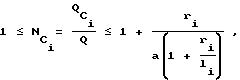
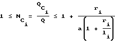
Q - масса заряда в скважине (кг), принимаемая по технологическим условиям в границах ![]()
![]()
kp - группа крепости взрываемой среды по CH и П;
kc - коэффициент, зависящий от типа и характера застройки охраняемого объекта;
A - среднегеометрическая из величин ширины и длины основания объекта, при ri/A≥1 принимается A = ri, м.The specified technical result is achieved by the fact that in the method of blasting near protected objects, including marking the location of the rows of wells within the area of blasted rocks, drilling wells, loading BB, installing the blast network and blasting charges in the wells shortly, marking the area of the blast site and drilling along a biaxial regular grid of wells with the lengths of the segments of the axial lines of the grid between their intersections with the contour of the drilling area equal to ![]()
Where ![]()
a is the technological step between the charging wells, m;
![]()
![]()
![]()
![]()
![]()
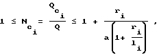
Q is the mass of charge in the well (kg), taken according to the technological conditions within ![]()
![]()
kp is the explosive strength group of the CH and P;
kc - coefficient depending on the type and nature of development of the protected facility;
A is the geometric mean of the values of the width and length of the base of the object, with r i / A≥1 A = r i , m is taken.
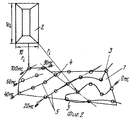
При исследовании технического уровня предлагаемого изобретения не было обнаружено технического решения, обладающего признаками предлагаемого способа, на основании чего можно считать, что предлагаемое решение соответствует критерию "технический уровень". Сущность изобретения поясняется чертежами, где на фиг. 1 дан план размещения скважин с зарядами в разрабатываемом участке для примера 1, на фиг. 2 - то же для примера 2. In the study of the technical level of the invention, no technical solution was found that has the features of the proposed method, on the basis of which it can be considered that the proposed solution meets the criterion of "technical level". The invention is illustrated by drawings, where in FIG. 1 shows a plan for the placement of wells with charges in the developed area for example 1, FIG. 2 is the same for example 2.
Способ осуществляется следующим образом. The method is as follows.
На предназначенном для взрывной разработки участке 1 (фиг. 1) вблизи охраняемого объекта 2 бурят зарядные скважины 3 диаметром, глубиной и шагом размещения по принятым для получения заданных результатов взрыва технологическим нормативам, заряжают каждую скважину массой взрывчатого вещества также технологически обусловленной величины и производят короткозамедленный взрыв, причем разметку площади участка и бурение осуществляют по двухосной регулярной сетке скважин так, чтобы получить длину отрезков l ее осевых линий 4 между их пересечениями с границами участка, приближено равной
![]()
где S - обуриваемая площадь разрабатываемого участка, м2,
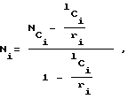
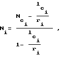
затем заряженные скважины группируют в ряды, разноудаленные от охраняемых объектов, монтируют взрывную сеть, размещая и взрывая в каждой короткозамедленной серии 5 число зарядов Ni

где ![]()
![]()
![]()
![]()
![]()
![]()
a - шаг между зарядными скважинами, м;
Q - масса заряда в скважине (кг), принимаемая по технологическим условиям в границах ![]()
![]()
![]()
kp - группа крепости взрываемой среды по CH и П;
kc - коэффициент, зависящий от типа и характера застройки охраняемого объекта.In section 1 intended for explosive development (Fig. 1),
![]()
where S is the drilling area of the developed area, m 2 ,
then the charged wells are grouped in rows that are different from the protected objects, the explosive network is mounted, placing and exploding in each short-
Where ![]()
![]()
![]()
![]()
![]()
![]()
a is the step between the charging wells, m;
Q is the mass of charge in the well (kg), taken according to the technological conditions within ![]()
![]()
![]()
kp is the explosive strength group of the CH and P;
kc - coefficient depending on the type and nature of development of the protected facility.
Например, для случаев, приведенных в Единых правилах безопасности при взрывных работах (НПО ОБТ, М., 1993, с. 181), принимается:
- одиночные производственные здания и сооружения с ж/бетонным или металлическим каркасом - 1,
- одиночные здания высотой до 2 - 3-х этажей с кирпичными и подобными стенами - 1,5,
- жилые поселки - 2.For example, for the cases described in the Unified Safety Rules for Blasting (NGO OBT, M., 1993, p. 181), it is accepted:
- single industrial buildings and structures with reinforced concrete or metal frame - 1,
- single buildings up to 2 - 3 floors high with brick and similar walls - 1.5,
- residential villages - 2.
Для других типов объектов с известной величиной допустимой скорости смещения (Vg, м/с)
![]()
A - среднегеометрическая из величин ширины и длины основания объекта, при ri/A>1 принимается A = ri, м.For other types of objects with a known value of the permissible displacement velocity (Vg, m / s)
![]()
A is the geometric mean of the values of the width and length of the base of the object, for r i / A> 1, A = r i , m is taken.
Примеры выполнения предлагаемого способа взрывания вблизи охраняемых объектов. Examples of the proposed method of blasting near protected objects.
Пример 1. Example 1
Производится (см. фиг. 1) взрывное дробление останца фортификационного монолита. Разрабатываемая бетонно-бутовая среда приравнена по крепости к VII группе грунтов классификации CH и П (kp=7). На расстоянии до ближнего края участка взрыва 22 м находится здание производственного назначения с железобетонным каркасом (kc=1), с габаритами по основанию 40х30 м ![]()
Мощность разрабатываемого слоя (высота уступа) - 5 м, площадь участка размещения зарядов (обуривания) S = 252 м2.Explosive crushing of the remnant of a fortification monolith is carried out (see Fig. 1). The developed concrete-rubble medium is equal in strength to the VII group of soils of the classification CH and P (kp = 7). At a distance of 22 m from the near edge of the blast site, there is a production building with a reinforced concrete frame (kc = 1), with dimensions on the base of 40x30 m ![]()
The thickness of the developed layer (step height) is 5 m, the area of the charge placement (drilling) area is S = 252 m 2 .
В соответствии с Нормативным справочником по буровзрывным работам проектируется массовый короткозамедленный взрыв вертикальных скважинных зарядов диаметром 0,11 м, длиной - 4,7 м, массой аммонита 6ЖВ - Q = 40 кг, при длине забойки - 1,7 м и шаге между зарядами в ряду - 4,1 м. При этом определяемые по известному способу параметры взрыва обеспечивают качественную проработку подошвы уступа и выход негабаритных кусков не более 10%. In accordance with the Normative Handbook on Drilling and Blasting Operations, a short-blown massive explosion of vertical borehole charges with a diameter of 0.11 m, a length of 4.7 m, an ammonite mass of 6ZHV is planned to be Q = 40 kg, with a stem length of 1.7 m and a step between charges of a row - 4.1 m. Moreover, the parameters of the explosion determined by the known method provide a high-quality study of the bottom of the ledge and the output of oversized pieces is not more than 10%.
По предлагаемому способу в проекте и при маркшейдерской разметке участка под бурение выставляются две пересекающиеся осевые линии сетки скважин с длиной отрезков в габаритах площади ![]()
![]()
Производят заряжание скважин и монтаж цепи короткозамедленного взрывания (КЗВ). Помещают в ближние к зданию пять групп (серий) КЗВ (расстояния 22-26 м) по 1 заряду:
![]()
![]()
![]()
![]()
округленно до целого N=1.The wells are charged and the short-circuit blast circuit (SCL) is installed. They are placed in the five groups (series) of short-range explosives (distances of 22-26 m), each charged to the building closest to the building:
![]()
![]()
![]()
![]()
rounded to the nearest integer N = 1.
В следующие три серии на расстоянии от здания 30,4 и 32 м - по 2 заряда:
![]()
![]()
![]()
![]()
(с округлением до целого).In the following three series at a distance from the building of 30.4 and 32 m - 2 charges:
![]()
![]()
![]()
![]()
(rounded to the nearest integer).
Затем в двух сериях на удалениях от охраняемого объекта (OO) 35,6 м и 38,8 м (принимается условие A=r) помещают по 3 заряда
![]()
![]()
![]()
![]()
Наконец, остальные пять зарядов группируют в ряд, взрываемый на одну серию, так как при расстоянии от ближнего заряда группы до OO - 41,5 м число зарядов Ni = 5.Then, in two series at a distance from the protected object (OO) of 35.6 m and 38.8 m (condition A = r is accepted), 3 charges are placed
![]()
![]()
![]()
![]()
Finally, the remaining five charges are grouped in a row exploded into one series, since at a distance from the near charge of the group to OO - 41.5 m, the number of charges N i = 5.
Очередность взрывания выполненным способом сгруппированных и распределенных по сериям КЗВ зарядов может быть произвольной, если не заданы дополнительные условия. Например, для ограничения разлета кусков раздробленного блока в сторону OO предпочтительно взрывать удаленные заряды в первую очередь (нулевая серия КЗВ) с последовательным наращиванием интервалов КЗВ по мере приближения к OO выстроенных по способу групп зарядов. The sequence of detonation of charges grouped and distributed over a series of short-circuit bombs in an executed manner can be arbitrary if additional conditions are not specified. For example, to limit the expansion of pieces of a fragmented block in the direction of OO, it is preferable to explode the remote charges in the first place (zero series KZV) with a sequential increase in the intervals of KZV as the groups of charges arranged by the method approach OO.
Пример 2. Example 2
На фиг. 2 показана схема выполнения способа при разработке выемки в массиве песчаника VII группы по CH и П (kp=7) и III категории трещиноватости по классификации МВКВД. Взрыв блока с высотой уступа 8 м и площадью 493 м2 проектируется в непосредственной близости (rmin = 12 м) от охраняемого объекта - секции плотины из ж/бетона с размерами по основанию 10х20 м. Допустимая по сейсмобезопасности величина скорости смещения для такого объекта - 0,5 м/с, что соответствует
![]()
По проекту из технологических нормативов принято: вертикальные скважинные заряды диаметром 0,175 м (безопасность для основания OO обеспечена, так как радиус трещинообразования в данном случае не превышает 10 м при расстоянии ближнего края участка до OO - 12 м), длиной 6,6 м, массой заряда аммонита 6ЖВ в скважине - Q = 140 кг. Шаг между зарядами в ряду - а = 6,2 м.In FIG. 2 shows a diagram of the method when developing a notch in a sandstone massif of group VII according to CH and P (kp = 7) and category III fracturing according to the classification of the MVKVD. An explosion of a block with a ledge height of 8 m and an area of 493 m 2 is designed in the immediate vicinity (r min = 12 m) from the guarded object - a dam section made of reinforced concrete with a base size of 10 x 20 m. The displacement rate permissible for seismic safety for such an object is 0.5 m / s, which corresponds
![]()
According to the project, from technological standards it is accepted: vertical borehole charges with a diameter of 0.175 m (safety for the OO base is ensured, since the radius of crack formation in this case does not exceed 10 m with a distance of the near edge of the section to OO of 12 m), 6.6 m long, weighing 6GV ammonite charge in the well - Q = 140 kg. The step between charges in a row is a = 6.2 m.
Для размещения скважин по площади участка выставляются оси сетки, имеющие длины отрезков между пересечениями с контуром участка обуривания по ![]()
![]()
Скважинные заряды проектной массы группируют по сериям КЗВ следующим образом:
- две серии по одному заряду на расстояниях от OO 12 м каждый;
- два заряда в серию на расстоянии 15 м;
- группа из 6-ти зарядов, ближайший к OO заряд в которой удален на 17,5 м (определения числа зарядов выполняют аналогично примеру 1).The downhole charges of the design mass are grouped in a series of short-circuit explosions as follows:
- two series of one charge at distances from OO 12 m each;
- two charges per series at a distance of 15 m;
- a group of 6 charges, in which the charge closest to the OO is 17.5 m away (determining the number of charges is carried out analogously to example 1).
В следующую группу зарядов с минимальным удалением от OO - 23 м можно включить все остальные заряды или увеличить массу заряда в скважине, поскольку:
![]()
а даже при неограниченной длине ряда li достаточно (см. правое ограничение NC)
![]()
![]()
Из технологической целесообразности оставляют заряды проектной массы и распределяют их, например, на две серии КЗВ по 6 и 7 шт. в каждой группе (фиг. 2).In the next group of charges with a minimum distance from OO - 23 m, you can include all other charges or increase the mass of charge in the well, because:
![]()
and even with unlimited row length l i is enough (see the right constraint N C )
![]()
![]()
From technological feasibility, they leave the projected mass charges and distribute them, for example, into two series of KZVs of 6 and 7 pcs. in each group (Fig. 2).
Реализация предложенного способа обеспечивает заданное проектом дробление среды, проработку подошвы уступа, компактный развал горной массы, направленный от OO разлет кусков и т.д. при гарантированной сейсмобезопасности взрыва и экономии бурения до 15% относительно известного способа производства буровзрывных работ. The implementation of the proposed method provides the project-specified crushing of the medium, the study of the soles of the ledge, compact camber of the rock mass, pieces directed from the OO, etc. with guaranteed seismic safety of the explosion and saving drilling up to 15% relative to the known method of drilling and blasting.
Claims (1)
где S - обуриваемая площадь разрабатываемого участка, м2,
заряды в скважинах группируют в ряды и монтируют взрывную сеть так, чтобы в каждой i-ой серии короткозамедленного взрывания число зарядов равнялось:
где
где a - технологический шаг между зарядными скважинами, м;
Q - масса заряда в скважине, кг;
где kp - группа крепости взрываемой среды по классификации СН и П;
kc - коэффициент, зависящий от типа и характера застройки охраняемого объекта;
А - среднегеометрическая из величин ширины и длины основания объекта, при ri/А > 1 принимается А = ri, м.A method of blasting explosives near protected objects, including marking the location of the rows of wells within the blast site, drilling wells, loading them with explosives, installing an explosive network and blasting charges in the wells shortly, characterized in that the marking of the area of the blast site and drilling biaxial regular grid of wells with the lengths of the segments of the axial lines of the grid between their intersections with the contour of the drilling area equal to
where S is the drilling area of the developed area, m 2 ,
charges in wells are grouped in rows and an explosive network is mounted so that in each i-th series of short-blown blasting, the number of charges is equal to:
Where
where a is the technological step between the charging wells, m;
Q is the mass of charge in the well, kg;
where kp is the explosive strength group of the classification of SN and P;
kc - coefficient depending on the type and nature of development of the protected facility;
A is the geometric mean of the width and length of the base of the object, for r i / A> 1, A = r i , m is taken.
Priority Applications (1)
| Application Number | Priority Date | Filing Date | Title |
|---|---|---|---|
| RU98106881A RU2139490C1 (en) | 1998-04-09 | 1998-04-09 | Method for blasting near guarded objects |
Applications Claiming Priority (1)
| Application Number | Priority Date | Filing Date | Title |
|---|---|---|---|
| RU98106881A RU2139490C1 (en) | 1998-04-09 | 1998-04-09 | Method for blasting near guarded objects |
Publications (1)
| Publication Number | Publication Date |
|---|---|
| RU2139490C1 true RU2139490C1 (en) | 1999-10-10 |
Family
ID=20204680
Family Applications (1)
| Application Number | Title | Priority Date | Filing Date |
|---|---|---|---|
| RU98106881A RU2139490C1 (en) | 1998-04-09 | 1998-04-09 | Method for blasting near guarded objects |
Country Status (1)
| Country | Link |
|---|---|
| RU (1) | RU2139490C1 (en) |
Citations (3)
| Publication number | Priority date | Publication date | Assignee | Title |
|---|---|---|---|---|
| GB1538494A (en) * | 1975-07-11 | 1979-01-17 | Canadian Ind | Method of underground mining |
| US4513665A (en) * | 1983-06-06 | 1985-04-30 | Occidental Oil Shale, Inc. | Method for loading explosive charges into blastholes formed in a subterranean formation |
| RU2062162C1 (en) * | 1993-06-03 | 1996-06-20 | Научно-исследовательский институт стали | Method of disintegrating metallic monolith |
-
1998
- 1998-04-09 RU RU98106881A patent/RU2139490C1/en not_active IP Right Cessation
Patent Citations (3)
| Publication number | Priority date | Publication date | Assignee | Title |
|---|---|---|---|---|
| GB1538494A (en) * | 1975-07-11 | 1979-01-17 | Canadian Ind | Method of underground mining |
| US4513665A (en) * | 1983-06-06 | 1985-04-30 | Occidental Oil Shale, Inc. | Method for loading explosive charges into blastholes formed in a subterranean formation |
| RU2062162C1 (en) * | 1993-06-03 | 1996-06-20 | Научно-исследовательский институт стали | Method of disintegrating metallic monolith |
Non-Patent Citations (1)
| Title |
|---|
| Б.Н.Кутузов. Взрывные работы. -М.: Недра, 1988, с. 232-238. * |
Similar Documents
| Publication | Publication Date | Title |
|---|---|---|
| Roy | Rock blasting: effects and operations | |
| CN102183184B (en) | Blast method for realizing vibration attenuation and protection of early-age concrete lining during tunnel construction | |
| Hagan et al. | Simulated rockburst experiment-an overview | |
| Hoshino et al. | Optimum delay interval design in delay blasting | |
| KR102312036B1 (en) | Pocket Charge Blasting Method | |
| RU2060447C1 (en) | Method for blasting off rocks | |
| RU2139490C1 (en) | Method for blasting near guarded objects | |
| Roy et al. | Strategic planning to reduce ground vibration, air overpressure and flyrock in a mine at a sensitive area | |
| CN110553559B (en) | Method for controlling explosive property by utilizing liquid carbon dioxide phase change | |
| Daou et al. | Monitoring of Blasting Operations Techniques and Assessment of Their Impacts on Groundwater in the Context of Underground Mining: Case of ROXGOLD SANU, Burkina Faso | |
| Roy et al. | Geological discontinuities, blast vibration and frag-mentation control—a case study | |
| Pal Roy et al. | Induced caving by blasting: innovative experiments in blasting gallery panels of underground coal mines of India | |
| Ouchterlony | Review of rock blasting and explosives engineering research at SveBeFo | |
| RU2475698C2 (en) | Method of blasting of rock mass | |
| RU2042817C1 (en) | Method for mining of thick deposits of solid minerals | |
| Eremenko | Blast design for improved performance and reduced surface vibration–a case study | |
| Sharma et al. | Assessment of blasting performance using electronic vis-à-vis shock tube detonators in strong garnet biotite sillimanite gneiss formations | |
| HAMIDUN | ASSESSMENT OF BLASTABILITY INDEX IN MASSIVE LIMESTONE FROM RAWANG QUARRY, SELANGOR | |
| O’telbayev | DETERMINATION OF FIELD BOUNDARY PARAMETERS IN DRILLING AND BLASTING PROCESSES IN OPEN PIT MINES | |
| CN113670147B (en) | Strip mine shallow-buried goaf blasting method | |
| Akinola et al. | Cost Modelling and Estimation of Drilling and Blasting Parameters affecting Guarry face and Fragmentations: A Case of Jolex Construction Company, Bassa, Plateau | |
| RU2026531C1 (en) | Group deep-hole outburst charge | |
| Pytel et al. | Numerical modeling of rockmass behaviour due to blasting operations in underground mines | |
| Maulenov et al. | DETERMINATION OF FIELD BOUNDARY PARAMETERS IN DRILLING AND BLASTING PROCESSES IN OPEN PIT MINES | |
| RU2163297C1 (en) | Method of mining of water-bearing deposits of water-soluble minerals |
Legal Events
| Date | Code | Title | Description |
|---|---|---|---|
| MM4A | The patent is invalid due to non-payment of fees |
Effective date: 20140410 |