RU2139373C1 - Method of forming spike-type protrusion - Google Patents
Method of forming spike-type protrusion Download PDFInfo
- Publication number
- RU2139373C1 RU2139373C1 RU98113601A RU98113601A RU2139373C1 RU 2139373 C1 RU2139373 C1 RU 2139373C1 RU 98113601 A RU98113601 A RU 98113601A RU 98113601 A RU98113601 A RU 98113601A RU 2139373 C1 RU2139373 C1 RU 2139373C1
- Authority
- RU
- Russia
- Prior art keywords
- melt
- tip
- gas
- condition
- interface
- Prior art date
Links
Images


Landscapes
- Crystals, And After-Treatments Of Crystals (AREA)
Abstract
Description
Изобретение относится к технологии обработки поверхности твердого тела, точнее к технологии формирования рельефа определенного типа - типа острия. (Под острием мы понимаем выступ поверхности с малым по отношению к его высоте минимальным радиусом кривизны поверхности вблизи вершины). Оно может быть использовано при изготовлении широкого класса полевых эмиссионных приборов, для создания зондов сканирующих микроскопов зондового типа, в устройствах сверхплотной записи и считывания информации, при разработке и создании различного рода датчиков, для декорирования поверхностей и т.д. The invention relates to a technology for processing a surface of a solid body, more specifically to a technology for forming a relief of a certain type — a tip type. (By a tip, we mean a protrusion of a surface with a small minimum radius of curvature of the surface relative to its height near the top). It can be used in the manufacture of a wide class of field emission devices, to create probes of scanning probe microscopes, in devices for superdense recording and reading of information, in the development and creation of various kinds of sensors, for decorating surfaces, etc.
Существующие в настоящее время методы получения выступов на поверхности с малым радиусом кривизны при вершине используют сложную и многоступенчатую технологию. Это травление граней монокристаллического материала, управляемое травление аморфных оптических волокон либо поликристаллических металлических проволок, выращивание монокристаллов из газовой фазы и т.д. Однако все эти процессы сложны, многостадийны и требуют много времени для получения острия, а управление их параметрами в широком диапазоне значений затруднительно. Currently existing methods for producing protrusions on a surface with a small radius of curvature at the apex use complex and multi-stage technology. This is the etching of the faces of a single-crystal material, controlled etching of amorphous optical fibers or polycrystalline metal wires, the growth of single crystals from the gas phase, etc. However, all these processes are complex, multi-stage and require a lot of time to obtain a tip, and it is difficult to control their parameters in a wide range of values.
Известен способ лазерной обработки материалов [В.В. Баженов и др. Письма в ЖТФ, 1987, т. 13, вып.20, с. 1235- 1239], в котором лазерным излучением осуществляют разогрев материала, в расплавленном состоянии обладающего повышенным коэффициентом отражения, в том числе материала с ρж/ρт> 1, где ρж и ρт - плотность материала при температуре плавления в жидком и твердом агрегатном состояниях, соответственно. При этом нагрев осуществляют выше температуры, соответствующей началу процесса неоднородного плавления, но не выше температуры формирования сплошного расплава на поверхности. Результатом обработки является получение рельефа, представляющего собой совокупность нерегулярно локализованных выступов на поверхности материала. Недостатком данного способа является невозможность получения острия.A known method of laser processing of materials [V.V. Bazhenov et al. Letters to ZhTF, 1987, v. 13, issue 20, p. 1235-1239], in which laser radiation is used to heat a material in the molten state with a high reflection coefficient, including material with ρ l / ρ t > 1, where ρ l and ρ t are the density of the material at the melting point in liquid and solid state of aggregation, respectively. When this heating is carried out above a temperature corresponding to the beginning of the process of inhomogeneous melting, but not above the temperature of formation of a solid melt on the surface. The result of the processing is to obtain a relief, which is a collection of irregularly localized protrusions on the surface of the material. The disadvantage of this method is the inability to obtain a tip.
Известен также способ обработки поверхности германия [D.C. Emmony, N.J. Phillips, J.H.Toyer, L.J. Willis. The topography of laser irradiated germanium J. Phys.D.: Appl. Phys., 1975, 8, pp. 1472-1479), в котором осуществляют разогрев поверхности германия, для которого ρж/ρт> 1, до формирования мелкой ванны расплава (глубина ванны много меньше ее ширины). При остывании созданной ванны расплава и перераспределении материала за счет различия плотностей жидкой и твердой фаз в центральной части ванны формируется цилиндрический выступ рельефа с существенно скругленной формой, вершины. Недостатками данного способа являются формирование гладкой вершины выступа, его малая, высота, т.е. невозможность получения острия.There is also known a method of surface treatment of Germany [DC Emmony, NJ Phillips, JHToyer, LJ Willis. The topography of laser irradiated germanium J. Phys. D.: Appl. Phys., 1975, 8, pp. 1472-1479), in which the surface of germanium is heated, for which ρ w / ρ t > 1, until the formation of a shallow melt bath (the depth of the bath is much less than its width). When the created melt bath cools down and material is redistributed due to the difference in the densities of the liquid and solid phases in the central part of the bath, a cylindrical projection of the relief with a substantially rounded shape, the top, is formed. The disadvantages of this method are the formation of a smooth peak of the protrusion, its small height, i.e. the inability to obtain a tip.
Наиболее близким по достигаемому результату к предлагаемому изобретению является выбранный нами в качестве прототипа способ обработки поверхности кремния [Е. Van de Riet, C. J.C.M. Nillesen, J. Dieleman. J. of Applied Physics, 1993, v.74(3), pp. 2008-2012] путем разогрева участка его поверхности серией импульсов излучения эксимерного лазера в вакууме с плотностью мощности не ниже пороговой для формирования расплава с последующим охлаждением до затвердевания. Способ позволяет получать хаотически расположенные микроострия со значительным разбросом геометрических параметров. Эффект наблюдался на кремнии. Этот способ, как и другие, не позволяет сформировать отдельное острие, управлять его размерами и пространственной локализацией. The closest to the achieved result to the proposed invention is the method of silicon surface treatment chosen by us as a prototype [E. Van de Riet, C. J.C.M. Nillesen, J. Dieleman. J. of Applied Physics, 1993, v. 74 (3), pp. 2008-2012] by heating a portion of its surface with a series of pulses of excimer laser radiation in vacuum with a power density not lower than the threshold for the formation of a melt with subsequent cooling to solidification. The method allows to obtain randomly located micropoints with a significant spread of geometric parameters. The effect was observed on silicon. This method, like others, does not allow to form a separate tip, to control its size and spatial localization.
Быстрое расширение областей применения острий делает необходимым разработку технологии оперативного и управляемого формирования на поверхности твердого тела острий с различными параметрами. The rapid expansion of the areas of application of the tips makes it necessary to develop technology for the rapid and controlled formation of tips with various parameters on the surface of a solid body.
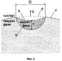
Нами теоретически обосновано и экспериментально подтверждено, что расплав, обладающий к моменту начала кристаллизации строго определенными свойствами и параметрами, в результате кристаллизации при определенных условиях охлаждения обеспечивает формирование острия типа конуса или гребня. Это происходит вследствие действия обнаруженного нами эффекта квазиподобия геометрии расплава, заключающегося в том, что расплав с некоторого момента времени t0 после начала кристаллизации в последующие моменты времени t (t>t0) остается геометрически квазиподобным себе в момент времени t0 (см. фиг. 1).We theoretically substantiated and experimentally confirmed that a melt, which had strictly defined properties and parameters at the time of crystallization, as a result of crystallization under certain cooling conditions, forms a tip like a cone or ridge. This is due to the effect of the quasi-similarity of the geometry of the melt that we discovered, namely, that the melt from a certain moment in time t 0 after the start of crystallization at subsequent times t (t> t 0 ) remains geometrically quasi-similar to itself at time t 0 (see Fig. . 1).
Предложенное нами изобретение позволяет стабильно и управляемо получать одиночное острие и совокупность таких острий на широком классе материалов с использованием широкого класса источников разогрева. Our invention allows us to stably and controllably obtain a single tip and a combination of such tips on a wide class of materials using a wide class of heating sources.
Заявленный нами технический эффект достигнут путем нагрева граничащей с газом зоны поверхностного слоя материала с ρж/ρт> 1, где ρж и ρт - плотность материала при температуре плавления в жидком и твердом агрегатном состояниях, соответственно, до получения расплава с последующим его охлаждением до затвердевания. Новым в способе является то, что расплав получают с односвязной границей раздела с газовой средой (односвязной областью на поверхности называют такую область, что любой замкнутый контур, расположенный в ней, ограничивает извне множество, состоящее сплошь из точек этой области), характерный размер D границы раздела выбирают из условия D ≤ D0, где Do= 3{σ/[(ρж-ρг)g]}1/2, σ - коэффициент поверхностного натяжения расплава, g - ускорение свободного падения, ρг - плотность газовой среды, максимальную глубину h расплава выбирают из условия h/D ≥ 0,05, охлаждение расплава осуществляют до кристаллизации при сохранении односвязной границы раздела, при этом время Тк кристаллизации сформированного расплава выбирают из условия Tк>Т0, где T0 - период первой гармоники собственных капиллярных колебаний границы раздела сформированного расплава.Our claimed technical effect was achieved by heating the gas surface zone of the surface layer of the material with ρ l / ρ t > 1, where ρ l and ρ t are the density of the material at the melting temperature in the liquid and solid state, respectively, until a melt is obtained with its subsequent cooling to harden. New in the method is that the melt is obtained with a simply connected interface with a gaseous medium (a simply connected area on the surface is such a region that any closed loop located inside it limits the set consisting entirely of points of this area from the outside), the characteristic size D of the boundary the section is selected from the condition D ≤ D 0 , where D o = 3 {σ / [(ρ w -ρ g ) g]} 1/2 , σ is the melt surface tension coefficient, g is the gravitational acceleration, ρ g is the gas density medium, the maximum depth h of the melt is selected from the condition h / D ≥ 0.05, cooling denie melt crystallization is carried out before, while maintaining a simply-connected interface, wherein the time T to the formed melt crystallization conditions selected from T k> T 0, wherein T 0 - period of the first harmonic oscillation own capillary partition formed melt boundary.
Для получения острия типа гребня (лезвия) формируют динамическую ванну расплава (под ванной здесь понимается граница раздела расплав - твердая фаза): ванну расплава перемещают вдоль поверхности материала по заданной траектории, перемещая источник нагрева относительно поверхности материала (см. п. 2). To obtain a tip of the ridge type (blade), a dynamic melt bath is formed (the bath here refers to the melt – solid phase interface): the melt bath is moved along the material surface along a predetermined path, moving the heating source relative to the material surface (see Section 2).
Если процесс осуществляют в вакууме, то из-за низкого теплоотвода в вакуум уменьшается вероятность образования очагов кристаллизации на свободной поверхности расплава и тем самым обеспечивается ее сохранение. При достаточно высоком вакууме обеспечивается почти полное отсутствие гетерогенных химических реакций, продукты которых могут иметь более высокую температуру плавления и, следовательно, образовывать прочную твердую пленку на поверхности расплава, граничащей с газом, уменьшая тем самым подвижность поверхности раздела расплав-газ, что приводит к увеличению радиуса кривизны вершины и уменьшению высоты острия. Осуществление способа в высоком вакууме обеспечивает получение малой величины радиуса кривизны поверхности вблизи вершины острия (см. п. 3). If the process is carried out in a vacuum, then, due to the low heat removal to the vacuum, the likelihood of crystallization on the free surface of the melt is reduced and, thus, it is preserved. With a sufficiently high vacuum, an almost complete absence of heterogeneous chemical reactions is ensured, the products of which can have a higher melting point and, therefore, form a strong solid film on the surface of the melt adjacent to the gas, thereby reducing the mobility of the melt-gas interface, which leads to an increase radius of curvature of the apex and a decrease in the height of the tip. The implementation of the method in high vacuum provides a small value of the radius of curvature of the surface near the tip of the tip (see paragraph 3).
При осуществлении способа в атмосфере химически инертного по отношению к расплаву газа также обеспечивается полное отсутствие нежелательных химических реакций и, как следствие, получение радиуса кривизны вершины острия малой величины (см. п. 4). When implementing the method in an atmosphere of a gas chemically inert with respect to the melt, the complete absence of undesirable chemical reactions is also ensured and, as a result, the radius of curvature of the tip tip is small (see paragraph 4).
При осуществлении способа в химически активной атмосфере, происходит искажение границы раздела расплав-газ, формируемой силами поверхностного натяжения, реактивным давлением паров продукта реакции и градиентом сил поверхностного натяжения, возникающим за счет растворения или присутствия на поверхности продукта реакции, изменяющего поверхностное натяжение. В результате в химически активной атмосфере по сравнению с инертной изменяются высота и радиус кривизны вершины острия (см. п.5). When implementing the method in a chemically active atmosphere, the melt-gas interface is distorted, formed by surface tension forces, the reactive vapor pressure of the reaction product and the gradient of surface tension forces arising from the dissolution or presence on the surface of the reaction product that changes the surface tension. As a result, in a chemically active atmosphere, in comparison with an inert atmosphere, the height and radius of curvature of the tip tip change (see Section 5).
При осуществлении способа в атмосфере легирующего газа за счет того, что время существования расплава к моменту формирования вершины острия максимально, а также за счет сегрегации легирующей примеси при кристаллизации, достигается повышенная концентрация легирующей примеси вблизи вершины острия (см. п. 6). When implementing the method in an atmosphere of a dopant gas due to the fact that the melt has a maximum lifetime at the time of formation of the tip tip, as well as due to the segregation of the dopant during crystallization, an increased concentration of the dopant near the tip of the tip is achieved (see paragraph 6).
Из числа материалов с ρж/ρт> 1 многие полупроводники при плавлении приобретают металлический характер проводимости (расплав материала приобретает свойства проводника). В электрическом поле на поверхность проводника действует давление, направленное по внешней нормали к поверхности и пропорциональное квадрату напряженности поля у поверхности. При осуществлении способа в электрическом поле это приводит к увеличению высоты острия (см. п. 7).Of the materials with ρ l / ρ t > 1, many semiconductors, upon melting, acquire the metallic character of conductivity (the molten material acquires the properties of a conductor). In an electric field, a pressure acts on the surface of the conductor, directed along the external normal to the surface and proportional to the square of the field strength at the surface. When implementing the method in an electric field, this leads to an increase in the height of the tip (see paragraph 7).
Повышение напряженности электрического поля на стадии формирования выпуклой поверхности раздела расплав-газ приводит к увеличению высоты острия (см. п. 8). An increase in the electric field strength at the stage of formation of a convex melt-gas interface leads to an increase in the height of the tip (see Sec. 8).
Предварительный нагрев материала до температуры меньшей температуры плавления приводит к увеличению времени существования расплава, что ведет к получению острий с более гладкой поверхностью (см. п. 9). Preheating the material to a temperature lower than the melting point leads to an increase in the lifetime of the melt, which leads to the formation of tips with a smoother surface (see section 9).
Предварительное охлаждение материала позволяет увеличить скорость кристаллизации и сократить время технологического цикла (см. п. 10). Pre-cooling of the material allows to increase the crystallization rate and reduce the time of the technological cycle (see p. 10).
Осуществление способа на материале, поверхностный слой которого толщиной меньше h является аморфным, позволяет получать монокристаллическое или поликристаллическое острие (см. п. 11). The implementation of the method on a material whose surface layer with a thickness less than h is amorphous, allows to obtain a single crystalline or polycrystalline tip (see paragraph 11).
На фиг. 1 схематически изображены два сечения острия на стадии автомодельного роста в процессе кристаллизации в моменты времени t0(а) и t(б), где t>t0, O - вершина формирующегося острия.In FIG. Figure 1 schematically shows two sections of the tip at the stage of self-similar growth during crystallization at time t 0 (a) and t (b), where t> t 0 , O is the tip of the forming tip.
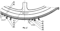
На фиг. 2 представлено схематическое изображение сечения сформированного расплава, граничащего со своей твердой фазой и газом (паром), где а - искривленная поверхность раздела жидкость-газ (мениск), b - поверхность раздела твердой и жидкой фазы (ванна), с - поверхность раздела твердой фазы с газом, d - разрушенный в результате плавления участок поверхности с, n - вектор внешней нормали к поверхности с, усредненный по поверхности d, h - максимальная глубина расплава в ванне (максимальное расстояние между ванной и мениском в направлении вектора n), D - характерный размер мениска а, измеряемый минимальным расстоянием между двумя параллельными плоскостями, касательными к нему и параллельными n. In FIG. 2 is a schematic representation of the cross section of the formed melt bordering its solid phase and gas (vapor), where a is the curved liquid-gas interface (meniscus), b is the solid-liquid phase interface (bath), and c is the solid phase interface with gas, d is the surface region c destroyed by melting, n is the external normal vector to surface c, averaged over surface d, h is the maximum melt depth in the bath (maximum distance between the bath and the meniscus in the direction of the vector n), D is the character ny and size of the meniscus, measured minimum distance between two parallel planes tangential to it and parallel to n.
На фиг. 3 представлена фотография острия, сформированного на поверхности монокристаллического кремния в вакууме под действием импульса свободной генерации лазера на неодимовом стекле. Угол наблюдения, отсчитываемый от вектора внешней нормали к исходной поверхности материала, близок к 80o (пример 1).In FIG. Figure 3 shows a photograph of the tip formed on the surface of single-crystal silicon in vacuum under the action of a pulse of free generation of a neodymium glass laser. The observation angle, measured from the external normal vector to the initial surface of the material, is close to 80 o (example 1).
На фиг. 4 представлены фотографии острий, сформированных на шлифованной поверхности поликристаллического германия в воздухе (а) и в азоте (б) под действием импульса свободной генерации лазера на неодимовом стекле. Угол наблюдения, отсчитываемый от вектора внешней нормали к исходной поверхности материала, близок к 80o (пример 4).In FIG. Figure 4 shows photographs of the tips formed on the polished surface of polycrystalline germanium in air (a) and in nitrogen (b) under the influence of a free generation pulse from a neodymium glass laser. The observation angle, measured from the external normal vector to the initial surface of the material, is close to 80 o (example 4).
Предложенный способ формирования выступа поверхности типа острия осуществляют следующим образом. The proposed method for forming a protrusion of a tip type surface is as follows.
Материалам с ρж/ρт> 1 являются материалы типа германия, кремния, галлия, висмута, льда, антимонида индия и др. Путем разогрева при поверхностной области материала формируют ванну расплава с односвязной (сплошной) границей раздела расплав-газ (см. фиг. 2), который затем охлаждают да завершения его кристаллизация при сохранении односвязной границы раздела. Моментом времени окончания формирования такого расплава и начала его кристаллизации считаем момент начала уменьшения объема расплава за счет его кристаллизации. Характерный размер D границы раздела расплав-газ (мениска) сформированного расплава выбирают из условия D≤D0, где Do= 3{σ/[(ρж-ρг)g]}1/2. Это условие выбора D обеспечивает преобладающее влияние капиллярных сил по сравнению, с гравитационными на формирование поверхности раздела расплав-газ и, следовательно, обеспечивает возможность ее сильного искривления и существенного перераспределения жидкофазного материала. Охлаждение расплава осуществляют, в основном, за счет теплопроводности в граничащую с ним твердую фазу, а также, в меньшей степени, за счет конвективного отвода тепла в газ, теплового излучения. Граница расплав-газ сформированного расплава приобретает форму вогнутого мениска (см. фиг. 2), так как при плавлении объем материала уменьшается ρж/ρт> 1 и стенки ванны расплава образованы твердофазным материалом, смачиваемым расплавом (расплав, сманивает материал, из твердой фазы которого он образован). Такая форма мениска обеспечивает, на первых этапах кристаллизации, фиксацию понижения уровня поверхности твердофазного материала (относительно исходной поверхности) вблизи границы мениска сформированного расплава, что на последующих этапах кристаллизации в силу сохранения массы материала приводит к повышению уровня (формированию выступа) поверхности твердофазного материала вблизи центра мениска.Materials with ρ f / ρ t > 1 are materials such as germanium, silicon, gallium, bismuth, ice, indium antimonide, etc. By heating at the surface region of the material, a melt bath is formed with a simply connected (solid) melt-gas interface (see Fig. . 2), which is then cooled until its crystallization is completed while maintaining a simply connected interface. The time of the end of the formation of such a melt and the beginning of its crystallization is the moment of the beginning of the decrease in the volume of the melt due to its crystallization. The characteristic size D of the melt-gas (meniscus) interface of the formed melt is selected from the condition D≤D 0 , where D o = 3 {σ / [(ρ w -ρ g ) g]} 1/2 . This condition for choosing D provides the predominant influence of capillary forces in comparison with gravitational forces on the formation of the melt-gas interface and, therefore, provides the possibility of its strong curvature and significant redistribution of the liquid-phase material. The cooling of the melt is carried out mainly due to thermal conductivity in the solid phase adjacent to it, and also, to a lesser extent, due to convective heat removal into the gas, thermal radiation. The melt-gas boundary of the formed melt takes the form of a concave meniscus (see Fig. 2), since during melting the volume of the material decreases ρ w / ρ t > 1 and the walls of the melt bath are formed by solid-phase material wetted by the melt (melt, lures the material from solid the phases of which it is formed). This form of the meniscus provides, at the first stages of crystallization, the fixation of lowering the surface level of the solid-phase material (relative to the initial surface) near the meniscus boundary of the formed melt, which, due to the conservation of the mass of the material, leads to an increase in the level (formation of a protrusion) of the surface of the solid-phase material near the center meniscus.
Если ванну расплава формируют в результате длительного разогрева (т.е. когда (aτ)1/2≫ D/2, где a - температуропроводность твердофазного материала, τ - время формирования расплава), то одновременно с формированием расплава происходит разогрев окружающего твердофазного материала. Поэтому при остывании расплава за счет отвода тепла в твердую фазу фронт кристаллизации (стенка ванны) вследствие низкого градиента температуры и, соответственно, переохлаждения, движется медленно. При этом расплав в ванне перераспределяется таким образом, что его поверхность, раздела с газом успевает приобретать квазиравновесную форму под действием сил поверхностного натяжения. В этом случае существование односвязной поверхности расплав-газ в процессе кристаллизации обычно обеспечивают за счет формирования расплава, глубина которого с увеличением расстояния от центра ванны преимущественно уменьшается. Если ванну с расплавом формируют импульсным источником разогрева, то время кристаллизации расплава может быть настолько малым, что расплав в ванне не успеет перераспределиться. Для обеспечения достаточного перераспределения материала расплава время кристаллизации сформированного расплава выбирают из условия Tк>T0, T0- период первой гармоники собственных капиллярных колебаний границы раздела расплав-газ сформированного расплава. Кроме того, для получения острия заметной по отношению к D высоты максимальную глубину расплава h выбирают из условия h/D≥0,05.If the melt bath is formed as a result of prolonged heating (i.e., when (aτ) 1/2 ≫ D / 2, where a is the thermal diffusivity of the solid-phase material, τ is the melt formation time), then the surrounding solid-phase material is heated simultaneously with the formation of the melt. Therefore, when the melt cools due to heat removal to the solid phase, the crystallization front (bath wall), due to the low temperature gradient and, accordingly, supercooling, moves slowly. In this case, the melt in the bath is redistributed in such a way that its surface, separated from the gas, has time to acquire a quasi-equilibrium shape under the influence of surface tension forces. In this case, the existence of a simply connected melt-gas surface during crystallization is usually ensured by the formation of a melt, the depth of which mainly decreases with increasing distance from the center of the bath. If the bath with the melt is formed by a pulsed heating source, then the crystallization time of the melt can be so short that the melt in the bath does not have time to redistribute. To ensure sufficient redistribution of the melt material, the crystallization time of the formed melt is chosen from the conditions T to > T 0 , T 0 is the period of the first harmonic of intrinsic capillary vibrations of the melt-gas interface of the formed melt. In addition, to obtain a tip noticeable with respect to D height, the maximum melt depth h is selected from the condition h / D≥0.05.
При выполнении вышеназванных условий процесс кристаллизации при остывании происходит следующим образом. Кристаллизация расплава, сформированного с выбранными размерами D и h, начинается и далее идет на границе раздела с твердой фазой, где реализуется максимальное переохлаждение и уже присутствует кристаллическая фаза. При этом за счет увеличения объема материала при кристаллизации (ρж/ρт> 1) и действия сил поверхностного натяжения происходит вытеснение и перераспределение жидкой фазы, динамическое изменение кривизны поверхности раздела расплав-газ, которая стремится принять равновесную форму. Кристаллизация уменьшает объем расплава и характерный размер мениска, что приводит к более быстрому затуханию капиллярных колебаний поверхности расплава. В центре зоны плавления постепенно формируется выступ жидкости (выпуклый мениск) и затем, с некоторого момента времени, реализуется механизм автомодельной геометрии поверхности расплава, т.е. происходит рост высоты выступа при формировании в отдельные моменты времени квазиподобных выпуклых менисков с уменьшающимися с течением времени радиусами кривизны (см. фиг. 1). Данный механизм обеспечивает формирование острия по окончании кристаллизации.When the above conditions are met, the crystallization process during cooling occurs as follows. The crystallization of the melt formed with the selected sizes D and h begins and then proceeds at the interface with the solid phase, where maximum supercooling is realized and the crystalline phase is already present. Moreover, due to an increase in the volume of the material during crystallization (ρ l / ρ t > 1) and the action of surface tension forces, the liquid phase is displaced and redistributed, and the curvature of the melt-gas interface is dynamically changed, which tends to take an equilibrium shape. Crystallization reduces the volume of the melt and the characteristic size of the meniscus, which leads to a more rapid attenuation of capillary oscillations of the surface of the melt. A liquid protrusion (convex meniscus) is gradually formed in the center of the melting zone and then, from a certain moment in time, the mechanism of self-similar geometry of the melt surface is realized, i.e. there is an increase in the height of the protrusion during the formation of quasi-like convex menisci at certain time instants with radii of curvature decreasing over time (see Fig. 1). This mechanism ensures the formation of the tip at the end of crystallization.
По предлагаемому способу нами была проведена большая серия работ на образцах различных материалов с ρж/ρт> 1 при различных характерных размерах D мениска и глубинах h расплава. В качестве источника нагрева использовали излучение свободной генерации лазера на стекле с неодимом (длительность импульса 10-3 с, длина волны λ = 1,06 мкм) или непрерывного CO2 лазера (λ = 10,6 мкм). Мы стабильно получали острия с варьируемыми в зависимости от параметров расплава геометрическими размерами в различных газовых средах (воздух, азот, гелий, вакуум, кислород, PCl3). Определение формы острия, измерение его высоты h0 относительно основания и радиуса кривизны r0 поверхности при вершине острия производили с помощью оптического микроскопа МБИ-6 и горизонтального микроскопа, входящего в комплект оптической, скамьи ОСК-З. Высоту рельефа и профиля острия определяли, методом наблюдения острий в направлении исходной плоской поверхности образца. Для случая формирования острий малых размеров измерение их геометрических параметров производилось с использованием сканирующего электронного микроскопа. При этом изображение получали при углах наблюдения, близких к скользящим.According to the proposed method, we carried out a large series of works on samples of various materials with ρ w / ρ t > 1 for various characteristic dimensions of the meniscus D and melt depths h. As a heating source, radiation was used from a free-running laser on a neodymium glass (pulse duration 10 -3 s, wavelength λ = 1.06 μm) or a continuous CO 2 laser (λ = 10.6 μm). We stably received tips with geometric dimensions varying depending on the melt parameters in various gaseous media (air, nitrogen, helium, vacuum, oxygen, PCl 3 ). Determining the shape of the tip, measuring its height h 0 relative to the base and the radius of curvature r 0 of the surface at the tip of the tip was carried out using an MBI-6 optical microscope and the horizontal microscope included in the optical bench OSK-Z. The height of the topography and profile of the tip was determined by observing the tips in the direction of the initial flat surface of the sample. For the case of the formation of small points, their geometric parameters were measured using a scanning electron microscope. The image was obtained at viewing angles close to moving.
Состав поверхностного сдоя острия при легировании исследовался, на растровом электронном микроскопе с рентгеновским спектральным микроанализатором "Camebax". The composition of the surface discharge of the tip during doping was studied using a scanning electron microscope with a Camebax X-ray spectral microanalyzer.
В примерах конкретного выполнения для удобства работы размеры зоны плавления были много меньше размеров образца материала. Плотность энергии, облучения Q выбирали не выше порога, выноса частиц расплава градиентом давления паров за пределы зоны формирования расплава. In the examples of a specific embodiment, for convenience, the dimensions of the melting zone were much smaller than the dimensions of the material sample. The energy density, irradiation Q was chosen no higher than the threshold, the removal of the melt particles by the vapor pressure gradient outside the zone of melt formation.
Время кристаллизации сформированного расплава Tк отсчитываемое от момента времени, окончания формирования расплава в примерах конкретного выполнения определяли по формуле (см. [1])
Tк ≅ h2/(4b2a), (1)
где a - температуропроводность твердофазного материала, b - решение уравнения c(Tm-T)/(Lmπ1/2) = b(exp(b2)), где c - удельная теплоемкость твердофазного материала, Tm - температура плавления материала, T - исходная температура твердофазного материала, Lm - удельная теплота кристаллизации.The crystallization time of the formed melt T k counted from the moment of time, the end of the formation of the melt in the examples of specific performance was determined by the formula (see [1])
T to ≅ h 2 / (4b 2 a), (1)
where a is the thermal diffusivity of the solid-phase material, b is the solution of the equation c (T m -T) / (L m π 1/2 ) = b (exp (b 2 )), where c is the specific heat of the solid-phase material, T m is the melting temperature material, T is the initial temperature of the solid-phase material, L m is the specific heat of crystallization.
Период T0 собственных капиллярных колебаний границы раздела сформированного расплава с газом в сформированной ванне находили по формуле (см. [2])
To≅ 2π/(ω2-γ2)1/2, (2)
где ω2= (2μg/D+8σμ3/(ρжD3))th(2μh/D), γ2= 8μ2ν/D2, ν - кинематическая вязкость расплава, μ = 3,832 - первый корень функции Бесселя первого порядка, g ≅ 980 см/с2.The period T 0 of intrinsic capillary oscillations of the interface between the formed melt and gas in the formed bath was found by the formula (see [2])
T o ≅ 2π / (ω 2 -γ 2 ) 1/2 , (2)
where ω 2 = (2μg / D + 8σμ 3 / (ρ and D 3 )) th (2μh / D), γ 2 = 8μ 2 ν / D 2 , ν is the kinematic viscosity of the melt, μ = 3,832 is the first root of the Bessel function first order, g ≅ 980 cm / s 2 .
Примеры конкретного выполнения
Пример 1. В качестве образца брали полированную пластину (0,2 х 1,0 х 1,0 см3) монокристаллического кремния (ρж/ρт≅ 1,1) n-типа с удельным сопротивлением 40 Ом•см. Пластину с начальной температурой T=293 К помещали в вакуум при остаточном давлении воздуха 2•10-3 мм рт.ст. Нагрев зоны поверхностного слоя осуществляли путем фокусировки импульсного излучения неодимового лазера в круглое пятно диаметром d на поверхности образца при близком к однородному распределении плотности энергии облучения Q. Параметры расплава D=90 мкм и h=35 мкм выбирали исходя из условий D<D0 (для кремния D0=1,8 см), h/D>0,05 и выполнения условия Tк>T0. Согласно формуле (1) время кристаллизации расплава Tк= 3,0•10-5 с (для кремния c ≅ 20 Дж/(К•моль), Lm=39600 Дж/моль, Tm= 1683 К, a=0,82 см2/с). По формуле (2) получили T0=1,4•10-5 с (для кремния σ = 860 дин/см, ρж 2,53 г/см2, ν = 0,0027 см2/с). Следовательно, критерий Tк>T0 выполнялся. Подходы к получению расплава заданной глубины с использованием лазерного излучения известны. Ванну расплава с выбранными параметрами D (в данном примере D является диаметром поверхности расплава) и h формировали импульсом лазерного излучения с Q=170 Дж/см2 и d= 90 мкм. Такой режим нагрева обеспечил формирование односвязной (сплошной) границы раздела расплава с паром. Остывание зоны расплава обеспечивалось в основном за счет теплопроводности в твердофазный материал. Сохранение односвязной поверхности расплав-газ обеспечивалось за счет выполнения условий h/D>0,05, Tк>T0 и уменьшения глубины ванны сформированного расплава в направлении от центра к его периферии.Case Studies
Example 1. As a sample, we took a polished plate (0.2 x 1.0 x 1.0 cm 3 ) of single-crystal silicon (ρ w / ρ t ≅ 1.1) of n-type with a specific resistance of 40 Ω • cm. A plate with an initial temperature T = 293 K was placed in vacuum at a residual air pressure of 2 • 10 -3 mm Hg. The zone of the surface layer was heated by focusing the pulsed radiation of a neodymium laser into a circular spot of diameter d on the sample surface with a close to uniform distribution of the radiation energy density Q. The melt parameters D = 90 μm and h = 35 μm were selected based on the conditions D <D 0 (for silicon D 0 = 1.8 cm), h / D> 0.05 and the fulfillment of the condition T to > T 0 . According to formula (1), the melt crystallization time T k = 3.0 • 10 -5 s (for silicon c ≅ 20 J / (K • mol), L m = 39600 J / mol, T m = 1683 K, a = 0 82 cm 2 / s). By the formula (2), T 0 = 1.4 • 10 -5 s was obtained (for silicon, σ = 860 dyne / cm, ρ w 2.53 g / cm 2 , ν = 0.0027 cm 2 / s). Therefore, the criterion T to > T 0 was fulfilled. Approaches to producing a melt of a given depth using laser radiation are known. The melt bath with the selected parameters D (in this example, D is the diameter of the melt surface) and h were formed by a laser pulse with Q = 170 J / cm 2 and d = 90 μm. This heating mode ensured the formation of a simply connected (solid) interface between the melt and the vapor. The cooling of the melt zone was ensured mainly due to thermal conductivity in the solid-phase material. The conservation of the simply connected melt-gas surface was ensured by fulfilling the conditions h / D> 0.05, T k > T 0 and decreasing the depth of the bath of the formed melt in the direction from the center to its periphery.
В результате кристаллизации на поверхности кремния получали острие высотой 11 мкм над исходной плоской поверхностью пластины иди h0 ≅ 12 мкм относительно основания острия. Верхняя часть острия (см. фиг. 3.) имела форму прямого кругового конуса с углом раствора ≅ 90o. Радиус кривизны поверхности вблизи вершины составлял 50 нм.As a result of crystallization on a silicon surface, a tip with a height of 11 μm above the initial flat surface of the plate was obtained, go h 0 ≅ 12 μm relative to the base of the tip. The upper part of the tip (see Fig. 3.) had the shape of a straight circular cone with a solution angle of ≅ 90 o . The radius of curvature of the surface near the apex was 50 nm.
Опыт воспроизводили 6 раз, облучая каждый раз свежий участок поверхности пластины. Разброс отклонений высот получаемых острий от приведенного составлял ≈7% и был связан с нестабильностью энергии в импульсе лазерного излучения (до 7%). The experiment was repeated 6 times, irradiating each time a fresh portion of the surface of the plate. The spread in the deviations of the heights of the obtained tips from the reduced one was ≈7% and was associated with the instability of energy in the laser pulse (up to 7%).
Пример 2. В качестве материала брали лед (ρж/ρт≅ 1,09) в виде прямоугольного параллелепипеда объемом 400 см3 (20x5x4 см3). Образец с начальной температурой T ≅ 260 К помещали в воздух при давлении 760 мм рт.ст. Разогрев прилегающего к поверхности слоя материала и формование движущейся ванны расплава осуществляли излучением непрерывного CO2 лазера. Пятно облучения на поверхности материала диаметром d и близким к однородному распределением плотности мощности q перемещали по прямолинейной траектории вдоль горизонтальной поверхности льда со скоростью v. В случае движущейся как целое ванны параметры D и h сформированного расплава определялись в поперечном сечении расплава (сечении расплава неподвижной относительно твердофазного материала плоскостью, перпендикулярной траектории). Момент времени окончания формирования области расплава в данном поперечном сечении и начала в нем кристаллизации совпадают с моментом времени начала уменьшения площади области расплава за счет кристаллизации. Для получения в результате кристаллизации острия типа гребня область расплава в поперечном сечении формируют со сплошной линией раздела с газом и процесс кристаллизации ведут при ее сохранении. Параметры расплава D=0,4 см и h=0,15 см выбирали исходя из условий D<D0 (для льда D0= 0,8 см), h/D>0,05 и выполнения условия Tк>T0. Согласно формуле (1) время кристаллизации расплава, которым в данном случае является время кристаллизации расплава в некотором неподвижном поперечном сечении, Tк≅ 120 с (для льда с=2,1 Дж/(К•г), Lm=334. Дж/г, Tm=273 К, a=0,011 см2/с). По формуле (2) получили T0 ≅ 10-2 с (для воды σ = 73 дин/см, ρж= 1,0 г/см2, v=0,017 см2/с). Следовательно, критерий Tк>T0 выполнялся. Подходы к получению расплава заданной глубины с использованием движущегося теплового источника известны. Ванну расплава с выбранными параметрами D и h формировали при плотности мощности облучения q=200 Вт/см2, диаметре пятна облучения d=0,4 см и скорости сканирования v= 0,8 см/с. Выбранный режим нагрева обеспечивал получение односвязной границы раздела расплав-газ и сплошной линии раздела расплав-газ в поперечном сечении расплава. Сохранение, в процессе кристаллизации сплошной линии раздела расплав-газ обеспечивалось за счет выполнения требований h/D>0,05, Tк>T0 и уменьшения глубины ванны сформированного расплава в направлении от центра к его периферии (в поперечном сечении). В результате кристаллизации на поверхности вдоль линии максимальной глубины плавления формировалось острие типа гребня высотой 170 мкм относительно основания и минимальным радиусом кривизны при вершине не более 5 мкм. Опыт: повторялся: три раза. Результат стабильно воспроизводился.Example 2. The material was ice (ρ w / ρ t ≅ 1.09) in the form of a rectangular parallelepiped with a volume of 400 cm 3 (20x5x4 cm 3 ). A sample with an initial temperature T ≅ 260 K was placed in air at a pressure of 760 mm Hg. The heating of the material layer adjacent to the surface and the formation of a moving melt pool were carried out by radiation from a continuous CO 2 laser. An irradiation spot on the surface of a material with a diameter d and a close to uniform distribution of power density q was moved along a rectilinear trajectory along the horizontal surface of the ice with velocity v. In the case of a bath moving as a whole, the parameters D and h of the formed melt were determined in the cross section of the melt (the cross section of the melt with a plane perpendicular to the solid-phase material perpendicular to the path). The time of the end of the formation of the melt region in a given cross section and the start of crystallization in it coincide with the time of the beginning of the decrease in the area of the melt region due to crystallization. In order to obtain a ridge-type tip as a result of crystallization, the melt region in the cross section is formed with a solid gas interface and the crystallization process is carried out while maintaining it. The melt parameters D = 0.4 cm and h = 0.15 cm were selected based on the conditions D <D 0 (for ice D 0 = 0.8 cm), h / D> 0.05 and the fulfillment of the condition T to > T 0 . According to formula (1), the melt crystallization time, which in this case is the melt crystallization time in some fixed cross section, T k ≅ 120 s (for ice with = 2.1 J / (K • g), L m = 334. J / g, T m = 273 K, a = 0.011 cm 2 / s). By the formula (2), T 0 ≅ 10 −2 s was obtained (for water, σ = 73 dyne / cm, ρ W = 1.0 g / cm 2 , v = 0.017 cm 2 / s). Therefore, the criterion T to > T 0 was fulfilled. Approaches to producing a melt of a given depth using a moving heat source are known. A melt bath with the selected parameters D and h was formed at an irradiation power density q = 200 W / cm 2 , an irradiation spot diameter d = 0.4 cm, and a scanning speed v = 0.8 cm / s. The selected heating mode ensured the production of a simply connected melt-gas interface and a solid melt-gas interface in the cross section of the melt. Preservation, during crystallization, of the solid melt-gas interface was ensured by fulfilling the requirements h / D> 0.05, T k > T 0 and reducing the depth of the bath of the formed melt in the direction from the center to its periphery (in cross section). As a result of crystallization on the surface along the line of maximum melting depth, a ridge-like tip was formed with a height of 170 μm relative to the base and a minimum radius of curvature at the apex of not more than 5 μm. Experience: repeated: three times. The result was stably reproduced.
Пример 3. В качестве образца, брали полированную пластину (0,8 x3x3 см3) монокристаллического кремния с удельным сопротивлением 1,2 кОм•см. Нагрев осуществлялся в атмосфере газа PCl3 при давлении газа 15 тор. Далее формирование острия осуществлялось в полном соответствии с примером N1. В результате получали острие высотой 11 мкм, углом раствора конуса 90o и минимальным радиусом кривизны при вершине не более 50 нм.Example 3. As a sample, we took a polished plate (0.8 x3x3 cm 3 ) of single-crystal silicon with a specific resistance of 1.2 kOhm · cm. Heating was carried out in a PCl 3 gas atmosphere at a gas pressure of 15 torr. Further, the formation of the tip was carried out in full accordance with example N1. The result was a tip with a height of 11 μm, a cone angle of 90 ° and a minimum radius of curvature at the apex of not more than 50 nm.
Материал острия имел проводимость n-типа. Поверхностный слой материала глубиной ≈1 мкм содержал атомы фосфора, измеренная концентрация которых у основания острия составляла ≈2,0•1015 см-3, а концентрация вблизи вершины острия была в 1,4 раз выше. Опыт воспроизводим
Пример 4. Брали шлифованную пластину (толщина 0,3 см и диаметр 3,0 см) поликристаллического германия (ρж/ρт≅ 1,069) с сопротивлением 0,5 Ом см. Образец при начальной температуре 290 К помещали в воздух (химически активная среда) при давлении 760 мм рт.ст. Нагрев зоны поверхностного слоя осуществляли путем фокусировки импульсного излучения неодимового лазера круглое пятно диаметром d на поверхности образца при близком к однородному распределении плотности энергии облучения Q. Параметры расплава D=0,1 см и h=200 мкм выбирали исходя из условий D<D0 (для германия D0 ≅ 1,0 см), h/D>0,05 и выполнения условия Tк>T0. Согласно формуле (1) время кристаллизации расплава составляет Tк ≅ 2,9•10-3 с (для германия с=23.3 Дж/(К•моль), Lm=34700 Дж/моль, Tm= 1211 К, a=0,35 см2/с). По формуле (2) получили T0= 1,0•10-3 с (для германия σ = 600 дин/см, ρж= 5,49 г/см2, ν = 0,00135 см2/с). Следовательно, критерий Tк>T0 выполнялся. Ванну расплава с выбранными параметрами D (в данном примере D является диаметром поверхности расплава) и h формировали импульсом лазерного излучения при Q ≅ 120 Дж/см2 и d ≅ 0,1 см. Такой нагрев обеспечивал формирование односвязной поверхности, раздела расплава, с паром. Остывание зоны расплава обеспечивалось в основном за счет теплопроводности в твердофазный материал. Сохранение сплошной поверхности расплав-газ обеспечивалось за счет выполнения, условий h/D>0,05, Tк>T0 и уменьшения глубины ванны расплава в направлении от центра к периферии расплава.The tip material had n-type conductivity. The surface layer of the material with a depth of ≈1 μm contained phosphorus atoms, the measured concentration of which at the base of the tip was ≈2.0 • 10 15 cm -3 , and the concentration near the tip of the tip was 1.4 times higher. Reproduce experience
Example 4. They took a polished plate (thickness 0.3 cm and diameter 3.0 cm) of polycrystalline germanium (ρ w / ρ t ≅ 1.069) with a resistance of 0.5 Ω cm. The sample was placed in air (chemically active) at an initial temperature of 290 K medium) at a pressure of 760 mm Hg The zone of the surface layer was heated by focusing the pulsed radiation of a neodymium laser with a round spot of diameter d on the surface of the sample with a close to uniform distribution of the radiation energy density Q. The melt parameters D = 0.1 cm and h = 200 μm were selected based on the conditions D <D 0 ( for Germany, D 0 ≅ 1.0 cm), h / D> 0.05 and the fulfillment of the condition T k > T 0 . According to formula (1), the melt crystallization time is T k ≅ 2.9 • 10 -3 s (for germanium c = 23.3 J / (K • mol), L m = 34700 J / mol, T m = 1211 K, a = 0.35 cm 2 / s). By the formula (2), T 0 = 1.0 • 10 -3 s was obtained (for Germany, σ = 600 dyne / cm, ρ W = 5.49 g / cm 2 , ν = 0.00135 cm 2 / s). Therefore, the criterion T to > T 0 was fulfilled. The melt bath with the selected parameters D (in this example, D is the diameter of the melt surface) and h were formed by a laser pulse at Q ≅ 120 J / cm 2 and d ≅ 0.1 cm. Such heating ensured the formation of a simply connected surface, the interface of the melt, with steam . The cooling of the melt zone was ensured mainly due to thermal conductivity in the solid-phase material. Maintaining a solid melt-gas surface was ensured by fulfilling the conditions h / D> 0.05, T k > T 0 and decreasing the depth of the melt bath in the direction from the center to the periphery of the melt.
В результате кристаллизации на поверхности германия получали конусообразное поликристаллическое острие высотой 288 мкм над исходной плоской поверхностью пластины, углом раствора конуса 45o и радиусом кривизны вершины острия 5 мкм (см. фиг. 4a). После остывания на поверхности, острия и в окрестности зоны облучения наблюдалось образование пленки, окислов германия. Высота сформированного острия, угол раствора конуса и радиус кривизны вершины острия при близких условиях (Q= 127 Дж/см2), но в азоте (760 мм рт.ст.) составили, соответственно, 126 мкм, ≈100o и ≈6 мкм (см. фиг. 46). Таким образом, в окислительной атмосфере, по сравнению с инертной, существенно возрастала величина высоты острия и уменьшался радиус кривизны вершины острия. Опыт воспроизводим.As a result of crystallization on the surface of germanium, a cone-shaped polycrystalline tip with a height of 288 μm above the initial flat surface of the plate, a cone angle of 45 ° and a radius of curvature of the tip tip of 5 μm was obtained (see Fig. 4a). After cooling on the surface, the tip and in the vicinity of the irradiation zone, the formation of a film and germanium oxides was observed. The height of the formed tip, the cone angle of the cone, and the radius of curvature of the tip tip under close conditions (Q = 127 J / cm 2 ) but in nitrogen (760 mmHg) were 126 μm, ≈100 o, and ≈6 μm, respectively (see Fig. 46). Thus, in an oxidizing atmosphere, in comparison with an inert atmosphere, the height of the tip increased substantially and the radius of curvature of the tip of the tip decreased. The experience is reproducible.
Пример 5. В качестве материала выбирали монокристаллический кремний. Полированная пластина имела следующие геометрические размеры: диаметр 4 см, толщина 0,6 см. Образец, размещенный в вакуумной камере, помещался на управляемый от ПЭВМ двухкоординатный стол. Задавалась дискретность линейных последовательных перемещений, равная 120 мкм. (Минимальная дискретность перемещений столика составляла 1 мкм). После каждого последовательного перемещения образца вдоль прямой линии (на расстояние 120 мкм) формировалось острие в полном соответствии с примером конкретного выполнения, описанном в примере 1 для кремния. Путем последовательных перемещений образца и формирования конусообразных острий получали систему из 5 острий, высота каждого из которых составляла 10 мкм, а расстояние между вершинами соседних острий было равно 120 мкм. При использовании скоростей перемещения образца v= 10-2см/с результат практически не зависел от того, производился разогрев с остановкой образца, либо без, поскольку типичная величина смещения образцы за время действия импульса лазерного излучения Δx = vτ = 10-5 см << D = 10-2 см.Example 5. Monocrystalline silicon was selected as the material. The polished plate had the following geometric dimensions: diameter 4 cm, thickness 0.6 cm. A sample placed in a vacuum chamber was placed on a two-coordinate table controlled by a PC. The discreteness of linear sequential displacements was set equal to 120 μm. (The minimum discreteness of movements of the table was 1 μm). After each successive movement of the sample along a straight line (at a distance of 120 μm), a tip was formed in full accordance with the specific embodiment described in Example 1 for silicon. By successive movements of the sample and the formation of cone-shaped points, a system of 5 points was obtained, the height of each of which was 10 μm, and the distance between the vertices of the neighboring points was 120 μm. When using the sample displacement velocities v = 10 -2 cm / s, the result was practically independent of whether heating was performed with the sample stopped or not, since the typical displacement of the samples during the duration of the laser pulse was Δx = vτ = 10 -5 cm << D = 10 -2 cm.
Таким образом, предлагаемый способ формирования выступа поверхности типа острия позволяет быстро и воспроизводимо получать острия на поверхности широкого класса технологических материалов. Thus, the proposed method of forming a protrusion of the surface of the type of tip allows you to quickly and reproducibly get the tip on the surface of a wide class of technological materials.
Величины характерных размеров этих выступов перекрывают большой диапазон значений, начиная с долей сантиметров и включая субмикронный уровень (область микро- и нанотехнологии). Способ позволяет варьировать их геометрические параметры: высоту, угол раствора конуса, размер основания, радиус кривизны вершины. The characteristic sizes of these protrusions cover a wide range of values, starting with a fraction of centimeters and including the submicron level (the field of micro- and nanotechnology). The method allows you to vary their geometric parameters: height, the angle of the cone, the size of the base, the radius of curvature of the vertex.
Особую ценность представляет возможность получения величин радиуса кривизны вершины острия в нанометровой области. Of particular value is the opportunity to obtain the radius of curvature of the tip apex in the nanometer region.
Данное изобретение превосходит возможности фотолитографии, методов химического и электрохимического травления, а также методов вытягивания острий из кварцевого стекла. Оно позволяет успешно решать задачу воспроизводимого и быстрого формирования острий заданного размера и пространственной конфигурации. Важным достоинством способа является его осуществимость на кремнии и германии - материалах, широко применяемых в микроэлектронике. This invention surpasses the capabilities of photolithography, chemical and electrochemical etching methods, as well as methods for drawing tips from quartz glass. It allows you to successfully solve the problem of reproducible and rapid formation of tips of a given size and spatial configuration. An important advantage of the method is its feasibility on silicon and germanium - materials widely used in microelectronics.
Технологическая база для реализации способа разработана: рынок предлагает высокостабильные источники импульсного и непрерывного лазерного излучения с необходимыми энергетическими параметрами и временными характеристиками, прецизионные программно-управляемые столы и т.д. Основные материалы для реализации способа производятся в достаточном объеме. The technological base for the implementation of the method has been developed: the market offers highly stable sources of pulsed and continuous laser radiation with the necessary energy parameters and time characteristics, precision programmable tables, etc. Basic materials for implementing the method are produced in sufficient quantities.
В заключение отметим, что область новых применений острий, микро- и наноострий неуклонно расширяется. In conclusion, we note that the field of new applications of tips, micro- and nano-tips is steadily expanding.
Литература
1. Рыкалин Н.Н., Углов А.А., Кокора А.Н. Лазерная обработка материалов. М., Машиностроение, 1975, 296 с.Literature
1. Rykalin N.N., Uglov A.A., Kokora A.N. Laser processing of materials. M., Mechanical Engineering, 1975, 296 p.
2. М. И. Трибельский. О форме поверхности жидкой фазы при плавлении сильнопоглощающих сред лазерным излучением. Квантовая электроника, т.5, N 4, с. 804-812, 1978. 2. M. I. Tribelsky. On the surface shape of the liquid phase during the melting of highly absorbing media by laser radiation. Quantum Electronics, v.5, N 4, p. 804-812, 1978.
Claims (11)
Priority Applications (1)
| Application Number | Priority Date | Filing Date | Title |
|---|---|---|---|
| RU98113601A RU2139373C1 (en) | 1998-07-07 | 1998-07-07 | Method of forming spike-type protrusion |
Applications Claiming Priority (1)
| Application Number | Priority Date | Filing Date | Title |
|---|---|---|---|
| RU98113601A RU2139373C1 (en) | 1998-07-07 | 1998-07-07 | Method of forming spike-type protrusion |
Publications (1)
| Publication Number | Publication Date |
|---|---|
| RU2139373C1 true RU2139373C1 (en) | 1999-10-10 |
Family
ID=20208495
Family Applications (1)
| Application Number | Title | Priority Date | Filing Date |
|---|---|---|---|
| RU98113601A RU2139373C1 (en) | 1998-07-07 | 1998-07-07 | Method of forming spike-type protrusion |
Country Status (1)
| Country | Link |
|---|---|
| RU (1) | RU2139373C1 (en) |
Citations (3)
| Publication number | Priority date | Publication date | Assignee | Title |
|---|---|---|---|---|
| FR2658839A1 (en) * | 1990-02-23 | 1991-08-30 | Thomson Csf | METHOD OF CONTROLLED GROWTH OF ACICULAR CRYSTALS AND APPLICATION TO THE PRODUCTION OF SPEED MICROCATHODS. |
| WO1996015298A1 (en) * | 1994-11-10 | 1996-05-23 | Jyosuke Nakata | Process for producing spherical crystal |
| RU2099808C1 (en) * | 1996-04-01 | 1997-12-20 | Евгений Инвиевич Гиваргизов | Process of growing of oriented systems of whiskers and gear for its implementation ( versions ) |
-
1998
- 1998-07-07 RU RU98113601A patent/RU2139373C1/en not_active IP Right Cessation
Patent Citations (3)
| Publication number | Priority date | Publication date | Assignee | Title |
|---|---|---|---|---|
| FR2658839A1 (en) * | 1990-02-23 | 1991-08-30 | Thomson Csf | METHOD OF CONTROLLED GROWTH OF ACICULAR CRYSTALS AND APPLICATION TO THE PRODUCTION OF SPEED MICROCATHODS. |
| WO1996015298A1 (en) * | 1994-11-10 | 1996-05-23 | Jyosuke Nakata | Process for producing spherical crystal |
| RU2099808C1 (en) * | 1996-04-01 | 1997-12-20 | Евгений Инвиевич Гиваргизов | Process of growing of oriented systems of whiskers and gear for its implementation ( versions ) |
Non-Patent Citations (1)
| Title |
|---|
| E. Van de Riet et al. J. of Applied Physics, 1993, у.74 (3), pp. 2008-2012. * |
Similar Documents
| Publication | Publication Date | Title |
|---|---|---|
| Cockayne et al. | Growth striations in vertically pulled oxide and fluoride single crystals | |
| Bonse et al. | Femtosecond laser ablation of silicon–modification thresholds and morphology | |
| Lim et al. | Enhancement of flow boiling heat transfer by laser-induced periodic surface structures using femtosecond laser | |
| KR20000016136A (en) | Method for treating articles with a plasma jet | |
| Eizenkop et al. | Single pulse excimer laser nanostructuring of thin silicon films: Nanosharp cones formation and a heat transfer problem | |
| Tang et al. | Growth of barium metaborate (BaB2O4) single crystal fibers by the laser-heated pedestal growth method | |
| Wysocki et al. | Near-field optical nanopatterning of crystalline silicon | |
| Schwabe et al. | Particle accumulation structures in time-dependent thermocapillary flow in a liquid bridge under microgravity | |
| Pedraza et al. | Laser ablation and column formation in silicon under oxygen-rich atmospheres | |
| Kim | Morphological instability under constitutional supercooling during the crystal growth of InSb from the melt under stabilizing thermal gradient | |
| Eizenkop et al. | Single-pulse excimer laser nanostructuring of silicon: A heat transfer problem and surface morphology | |
| RU2139373C1 (en) | Method of forming spike-type protrusion | |
| RU2752821C1 (en) | Method for obtaining nanostructured metal billet by laser treatment | |
| Lu et al. | Wet-chemical etching of Mn-Zn ferrite by focused Ar+-laser irradiation in H3PO4 | |
| Moening et al. | Formation of conical silicon tips with nanoscale sharpness by localized laser irradiation | |
| Salihoglu et al. | Femtosecond laser crystallization of amorphous Ge | |
| Haessner et al. | Laser-induced dislocation structures in copper single crystals | |
| Toro et al. | Anisotropic nanostructure formation by vapor etching of ion tracks in α-quartz | |
| Reconstruction of vicinal SiC surfaces in liquid silicon at high temperature | ||
| Glebovsky et al. | The characteristic features of growth and the real structure of tungsten tube crystals | |
| Weishart et al. | Morphological stability during GaAs solution growth: liquid phase epitaxy versus the travelling heater method | |
| JP3989424B2 (en) | Method for producing fine particles | |
| Khomich et al. | Formation of surface micro and nanostructures when exposed to laser UV and VUV radiation of nanosecond duration | |
| Pestov et al. | Laser-induced formation of conical bumps on the surface of superrefractory metals | |
| RU2756777C1 (en) | Method for obtaining microstructures on the surface of a semiconductor |
Legal Events
| Date | Code | Title | Description |
|---|---|---|---|
| MM4A | The patent is invalid due to non-payment of fees |
Effective date: 20110708 |
|
| RZ4A | Other changes in the information about an invention | ||
| MM4A | The patent is invalid due to non-payment of fees |
Effective date: 20140708 |