RU2139359C1 - Plant for processing of wastes of metallurgical production - Google Patents
Plant for processing of wastes of metallurgical production Download PDFInfo
- Publication number
- RU2139359C1 RU2139359C1 RU98107885A RU98107885A RU2139359C1 RU 2139359 C1 RU2139359 C1 RU 2139359C1 RU 98107885 A RU98107885 A RU 98107885A RU 98107885 A RU98107885 A RU 98107885A RU 2139359 C1 RU2139359 C1 RU 2139359C1
- Authority
- RU
- Russia
- Prior art keywords
- grate
- slag
- plant
- screen
- fraction
- Prior art date
Links
Images
Classifications
-
- Y—GENERAL TAGGING OF NEW TECHNOLOGICAL DEVELOPMENTS; GENERAL TAGGING OF CROSS-SECTIONAL TECHNOLOGIES SPANNING OVER SEVERAL SECTIONS OF THE IPC; TECHNICAL SUBJECTS COVERED BY FORMER USPC CROSS-REFERENCE ART COLLECTIONS [XRACs] AND DIGESTS
- Y02—TECHNOLOGIES OR APPLICATIONS FOR MITIGATION OR ADAPTATION AGAINST CLIMATE CHANGE
- Y02P—CLIMATE CHANGE MITIGATION TECHNOLOGIES IN THE PRODUCTION OR PROCESSING OF GOODS
- Y02P10/00—Technologies related to metal processing
- Y02P10/20—Recycling
-
- Y—GENERAL TAGGING OF NEW TECHNOLOGICAL DEVELOPMENTS; GENERAL TAGGING OF CROSS-SECTIONAL TECHNOLOGIES SPANNING OVER SEVERAL SECTIONS OF THE IPC; TECHNICAL SUBJECTS COVERED BY FORMER USPC CROSS-REFERENCE ART COLLECTIONS [XRACs] AND DIGESTS
- Y02—TECHNOLOGIES OR APPLICATIONS FOR MITIGATION OR ADAPTATION AGAINST CLIMATE CHANGE
- Y02W—CLIMATE CHANGE MITIGATION TECHNOLOGIES RELATED TO WASTEWATER TREATMENT OR WASTE MANAGEMENT
- Y02W30/00—Technologies for solid waste management
- Y02W30/50—Reuse, recycling or recovery technologies
Abstract
Description
Изобретение относится к металлургии, конкретно к установкам по переработке отходов металлургического производства, для получения шихтовых материалов, которые могут быть использованы в различных металлургических переделах: при спекании агломерационной шихты, в доменном и литейном производствах, в сталеплавильных агрегатах, а также для получения шлака. The invention relates to metallurgy, and specifically to installations for the processing of waste from metallurgical production, for the production of charge materials that can be used in various metallurgical processes: during sintering of the sinter charge, in blast furnace and foundry, in steelmaking units, as well as for the production of slag.
Известна технология и установка для получения концентрата с низким содержанием кремнезема (Тулин Н.А. и др. Развитие бескоксовой металлургии. М. Металлургия. 1987. с. 106). Концентрат был получен на технологических секциях 1-4 по разработанной институтом "Механобрчермет" технологии магнитного обогащения: три стадии бесшарового измельчения и пять стадий магнитной сепарации. Для получения концентрата с содержанием кремнезема < 3,6% подавали исходную руду, содержащую 57,7% легкообогатимых магнезитовых и гематито-магнезитовых кварцитов против 50,0% в руде, применяемой для получения рядового концентрата. A known technology and installation for producing a concentrate with a low silica content (Tulin N.A. et al. Development of coke-free metallurgy. M. Metallurgy. 1987. p. 106). The concentrate was obtained in technological sections 1-4 according to the technology of magnetic enrichment developed by the Institute of Mechanobrchermet: three stages of ballless grinding and five stages of magnetic separation. To obtain a concentrate with silica content <3.6%, an initial ore was fed containing 57.7% of easily-enriched magnesite and hematite-magnesite quartzites compared to 50.0% in the ore used to obtain ordinary concentrate.
Недостатками указанной установки являются относительно невысокое содержание железа в виде окислов (62-68%), высокая себестоимость производства концентратов, а также ограниченное применение. The disadvantages of this installation are the relatively low iron content in the form of oxides (62-68%), the high cost of production of concentrates, and limited use.
Известна также установка получения металлического концентрата, включающая последовательные операции дробления исходного материала, очистку, сортировку по крупности и магнитную сепарацию (Патент РФ N 2044075). Also known is a plant for producing a metal concentrate, including sequential operations of crushing the source material, cleaning, sorting by size and magnetic separation (RF Patent N 2044075).
Отобранный магнитный материал подвергают дроблению, сортируют на наклонной решетке с ячейкой 250 мм, прошедший через решетку полупродукт порциями загружают в проходной очистной барабан, а на выходе из него обеспечивают разделение продукта на фракции; 50 мм и менее 50 мм, после чего каждую фракцию подают раздельно через ленточные транспортеры на узлы магнитной сепарации, при этом мелкий магнитный продукт очистки подают в односитный грохот и разделяют его на фракции: 0-10 мм и 10-50 мм и подают их на узлы магнитной сепарации, разделение материала на магнитную и немагнитную составляющие производят на электромагнитных шкивах. The selected magnetic material is crushed, sorted on an inclined grate with a cell of 250 mm, the semi-product passing through the grate is portionwise loaded into the in-line cleaning drum, and at the exit from it, the product is divided into fractions; 50 mm and less than 50 mm, after which each fraction is fed separately through conveyor belts to the magnetic separation units, while the small magnetic cleaning product is fed into a single-sieve screen and divided into fractions: 0-10 mm and 10-50 mm and fed to nodes of magnetic separation, the separation of the material into magnetic and non-magnetic components is carried out on electromagnetic pulleys.
Недостатками указанной установки являются пылевыделение на рабочих местах и низкая степень чистоты кусков железа от шлака мелкой фракции. Техническая задача - устранение указанных недостатков и повышение стабильности работы установки. The disadvantages of this installation are dust emission at workplaces and a low degree of purity of pieces of iron from fine slag. The technical task is to eliminate these shortcomings and increase the stability of the installation.
Технический результат достигается тем, что установка по переработке отходов металлургического производства снабжена системой предварительного увлажнения шлака, установленной над приемным бункером, а грохот имеет дополнительную решетку с ячейкой 5x5 мм, расположенную под основной решеткой и соединенную конвейером с бункером сбора шлака, при этом разделительная перфорированная решетка барабана выполнена с ячейкой 40x40 мм, а основная решетка грохота с ячейкой 20x20 мм. The technical result is achieved by the fact that the metallurgical waste processing plant is equipped with a slag pre-humidification system installed above the receiving hopper, and the screen has an additional grate with a 5x5 mm cell located under the main grate and connected by a conveyor to the slag collecting hopper, while the separation perforated grate the drum is made with a cell of 40x40 mm, and the main screen grill with a cell of 20x20 mm.
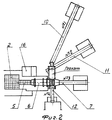
На фиг. 1 изображена схема установки по переработке отходов металлургического производства, на фиг. 2 - общий вид установки сверху. In FIG. 1 shows a diagram of a plant for processing waste from metallurgical production, FIG. 2 is a general view of the installation from above.
Установка по переработке отходов металлургического производства включает приемный бункер 1 для загрузки в установку доменного шлака для дальнейшей его переработки. The metallurgical waste processing plant includes a receiving hopper 1 for loading blast furnace slag into the plant for further processing.
Максимальный размер кусков шлака должен соответствовать размеру ячейки решетки 2, установленной в верхней части приемного бункера 1 и составляет 250x250 мм. При большем размере кусков шлак перед загрузкой в бункер должен быть предварительно отсеян с ячейками 250x250 мм. При необходимости для сброса негабарита с решетки бункера возможно использование тельфера с клещевым захватом грузоподъемностью 0,15 т. The maximum size of the slag pieces must correspond to the size of the
Для защиты окружающей среды и рабочих мест от пыли осуществляется из системы 3 предварительное увлажнение шлака установленной над приемным бункером (поливомоечная машина, можно использовать стационарную емкость для воды). To protect the environment and workplaces from dust, slag is preliminarily moistened from system 3 above the receiving hopper (watering machine, a stationary water tank can be used).
Установка состоит из следующих частей: опорных металлических конструкций 4, питателя (пластинчатого конвейера) 5, галтовочного барабана 6, ленточного транспортера 7 для фракции 40-250 мм, бункеров 8 для разделения на металлическую и неметаллическую части, грохота 9, ленточного транспортера 10 для фракции 20-40, ленточного транспортера 11 для фракции 5-20, ленточного транспортера 12 для фракции 0-5, бункера 13 для сбора шлака и металла фракции 0-5 мм. The installation consists of the following parts: supporting metal structures 4, feeder (plate conveyor) 5,
Из бункера 1 с помощью питателя 5 шлак поступает во вращающийся галтовочный барабан 6, в котором с помощью зубьев происходит предварительное отделение металлической магнитной части от шлака. Галтовочный барабан 6 имеет решетку с размерами ячейки 40 мм, которая служит для разделения шлака на две фракции 0-40 мм и 40-250 мм. Фракция 40-250 мм поступает на ленточный транспортер 7, а фракция 0-40 мм поступает в грохот 9. Грохот имеет две решетки: основную решетку 14 с размерами ячейки 20 мм и дополнительную решетку 15 с размерами ячейки 5 мм. From the hopper 1, with the help of the
На грохоте происходит разделение фракции 0-40 мм на три фракции: 20-40 мм; 5-20 мм; 0-5 мм, каждая из которых с помощью ленточных транспортеров 10,11,12 доставляется в бункера готовой продукции 8,13 В верхней части ленточных транспортеров 7,10,11,12 установлены магнитные барабаны, с помощью которых происходит разделение шлака на магнитную и немагнитную составляющие. On the screen, the fraction of 0-40 mm is divided into three fractions: 20-40 mm; 5-20 mm; 0-5 mm, each of which with the help of
Бункера готовой продукции разделены соответственно на магнитную и немагнитную части. The finished product bins are divided respectively into magnetic and non-magnetic parts.
Для защиты окружающей среды и рабочих мест от пыли осуществляется предварительное увлажнение шлака с помощью поливомоечной машины, при необходимости на установке можно использовать стационарную емкость для воды. To protect the environment and workplaces from dust, the slag is preliminarily wetted using a watering machine; if necessary, a stationary water tank can be used at the installation.
Получены промышленные партии металлического концентрата:
составы фракции 0-20 мм были применены в технологии подготовки к спеканию агломерационной шихты;
составы фракции 20-40 мм - в качестве части металлодобавок в технологии ведения доменной печи;
составы фракции 40-250 мм - в металлозавалке мартеновских и электродуговых печей.Received industrial batches of metal concentrate:
the compositions of the 0-20 mm fraction were used in the preparation technology for sintering the sinter mixture;
the composition of the fraction of 20-40 mm - as part of metal additives in the technology of maintaining a blast furnace;
the compositions of the fraction of 40-250 mm - in the metal filling of open-hearth and electric arc furnaces.
Металлический концентрат, полученный на установке по переработке отходов металлургического производства позволяет экономить энергетические ресурсы: The metal concentrate obtained at the plant for the processing of waste from metallurgical production saves energy resources:
Claims (2)
Priority Applications (1)
| Application Number | Priority Date | Filing Date | Title |
|---|---|---|---|
| RU98107885A RU2139359C1 (en) | 1998-04-28 | 1998-04-28 | Plant for processing of wastes of metallurgical production |
Applications Claiming Priority (1)
| Application Number | Priority Date | Filing Date | Title |
|---|---|---|---|
| RU98107885A RU2139359C1 (en) | 1998-04-28 | 1998-04-28 | Plant for processing of wastes of metallurgical production |
Publications (1)
| Publication Number | Publication Date |
|---|---|
| RU2139359C1 true RU2139359C1 (en) | 1999-10-10 |
Family
ID=20205265
Family Applications (1)
| Application Number | Title | Priority Date | Filing Date |
|---|---|---|---|
| RU98107885A RU2139359C1 (en) | 1998-04-28 | 1998-04-28 | Plant for processing of wastes of metallurgical production |
Country Status (1)
| Country | Link |
|---|---|
| RU (1) | RU2139359C1 (en) |
Cited By (2)
| Publication number | Priority date | Publication date | Assignee | Title |
|---|---|---|---|---|
| WO2006000553A1 (en) * | 2004-06-24 | 2006-01-05 | S.A. Lhoist Recherche Et Developpement | Mobile device for the granulation of dairy fines |
| CN113943842A (en) * | 2021-10-27 | 2022-01-18 | 莱芜钢铁集团泰东实业有限公司 | Multi-component blast furnace dust removal device is with removing heavy system |
-
1998
- 1998-04-28 RU RU98107885A patent/RU2139359C1/en active
Non-Patent Citations (1)
| Title |
|---|
| Тулин Н.А. Развитие бескоксовой металлургии. - М.: Металлургия, 1987, с. 106. * |
Cited By (4)
| Publication number | Priority date | Publication date | Assignee | Title |
|---|---|---|---|---|
| WO2006000553A1 (en) * | 2004-06-24 | 2006-01-05 | S.A. Lhoist Recherche Et Developpement | Mobile device for the granulation of dairy fines |
| BE1016098A3 (en) * | 2004-06-24 | 2006-03-07 | Lhoist Rech & Dev Sa | Mobile slag fine granulation. |
| US7740196B2 (en) | 2004-06-24 | 2010-06-22 | S.A. Lhoist Recherche Et Developpement | Mobile device for granulating slag fines |
| CN113943842A (en) * | 2021-10-27 | 2022-01-18 | 莱芜钢铁集团泰东实业有限公司 | Multi-component blast furnace dust removal device is with removing heavy system |
Similar Documents
| Publication | Publication Date | Title |
|---|---|---|
| CN105195313B (en) | The method that metal and combustible are reclaimed from domestic waste incineration residue | |
| CN102688880B (en) | Method for efficiently recovering and reselecting steel slag | |
| CN108239684A (en) | A kind of converter slag New Process for Treatment | |
| CN104245144B (en) | Method and system for processing slag material | |
| CN101716553A (en) | Kiln slag processing technology of zinc volatilizing kiln | |
| CN1924025A (en) | Process for treating slag steel | |
| CN108187880B (en) | A kind of slag advanced treatment process | |
| CN109234486A (en) | A kind of method and device thereof of coal-based direct reduction baked for producing reduced iron | |
| CN112934378B (en) | Preparation system for producing building material products by gradient utilization of hot stuffy steel slag | |
| CN109734335A (en) | A method of high-quality steel-making slag powder is produced based on steel slag modifying agent | |
| CN105396673A (en) | Method for producing grinding nickel-iron slag and steel slag composite powder through grinding by using vertical mill | |
| CN109092844B (en) | Steel slag multistage treatment method | |
| CN103100546A (en) | Stainless steel slag dry and wet combination treatment process | |
| CN106116196A (en) | A kind of vertical mill grinding slag, lithium slag composite powder production method | |
| RU2139359C1 (en) | Plant for processing of wastes of metallurgical production | |
| CN206028297U (en) | Waste incineration furnace slag processing system | |
| CN105217987A (en) | The complex slag utilizing electric arc furnace restored slag and flyash to produce and preparation technology thereof | |
| CN108393177A (en) | Ground slag machining production line | |
| US5456992A (en) | Process for battery recycling | |
| CN106636670A (en) | System and method for preparing ferronickel from laterite-nickel ore | |
| KR20000037285A (en) | Briquetting method of iron powder in convert slag | |
| CN207238208U (en) | One kind steel-making tailings resource reclaiming system | |
| CN110643756A (en) | Recovery device and recovery method for steel slag under steel making furnace | |
| CN106116195A (en) | A kind of vertical mill grinding slag, lithium slag add modifying agent composite powder production method | |
| CN110039064A (en) | A method of reproducibility iron powder is prepared using blast furnace dust smelted furnace cinder |