RU2139161C1 - Method and apparatus for assembling inner parts of articles with coiled springs - Google Patents
Method and apparatus for assembling inner parts of articles with coiled springs Download PDFInfo
- Publication number
- RU2139161C1 RU2139161C1 RU97116268A RU97116268A RU2139161C1 RU 2139161 C1 RU2139161 C1 RU 2139161C1 RU 97116268 A RU97116268 A RU 97116268A RU 97116268 A RU97116268 A RU 97116268A RU 2139161 C1 RU2139161 C1 RU 2139161C1
- Authority
- RU
- Russia
- Prior art keywords
- springs
- conveyor
- spring
- devices
- manufacturing
- Prior art date
Links
Images


Classifications
-
- B—PERFORMING OPERATIONS; TRANSPORTING
- B68—SADDLERY; UPHOLSTERY
- B68G—METHODS, EQUIPMENT, OR MACHINES FOR USE IN UPHOLSTERING; UPHOLSTERY NOT OTHERWISE PROVIDED FOR
- B68G9/00—Placing upholstery springs in pockets; Fitting springs in upholstery
-
- B—PERFORMING OPERATIONS; TRANSPORTING
- B21—MECHANICAL METAL-WORKING WITHOUT ESSENTIALLY REMOVING MATERIAL; PUNCHING METAL
- B21F—WORKING OR PROCESSING OF METAL WIRE
- B21F27/00—Making wire network, i.e. wire nets
- B21F27/12—Making special types or portions of network by methods or means specially adapted therefor
- B21F27/16—Making special types or portions of network by methods or means specially adapted therefor for spring mattresses
-
- B—PERFORMING OPERATIONS; TRANSPORTING
- B21—MECHANICAL METAL-WORKING WITHOUT ESSENTIALLY REMOVING MATERIAL; PUNCHING METAL
- B21F—WORKING OR PROCESSING OF METAL WIRE
- B21F33/00—Tools or devices specially designed for handling or processing wire fabrics or the like
- B21F33/04—Connecting ends of helical springs for mattresses
Landscapes
- Engineering & Computer Science (AREA)
- Mechanical Engineering (AREA)
- Wire Processing (AREA)
- Springs (AREA)
- Unwinding Webs (AREA)
Abstract
Description
Область техники
Изобретение относится к изготовлению и сборке внутренних частей изделий, содержащих спиральные пружины, и в особенности к способу и устройству для подачи и расположения пружин с зазорами друг относительно друга для установки в такие пружинные внутренние части.Technical field
The invention relates to the manufacture and assembly of the internal parts of products containing coil springs, and in particular to a method and device for feeding and arranging springs with gaps relative to each other for installation in such spring internal parts.
Уровень техники
При производстве пружинных внутренних частей изделий, например, таких, какие используются для изготовления внутренних пружинных модулей матрацев и подобных изделий, используются машины по сборке пружин для объединения вместе рядов спиральных пружин в блоки, которые обычно имеют прямоугольную форму. Такие блоки пружин обычно собираются как множество вертикальных спиральных пружин конической формы, часто выполненных в форме песочных часов, установленных на общей горизонтальной плоскости в решетке. Более предпочтительные конструкции машин по изготовлению внутренних пружин в изделиях содержат навивочное устройство, изготавливающее индивидуальные пружины из непрерывной проволоки и подающее их по мере изготовления к сборочному устройству.State of the art
In the manufacture of spring internal parts of products, such as those used to make internal spring modules of mattresses and similar products, spring assembly machines are used to join together the rows of coil springs into blocks that are usually rectangular in shape. Such spring blocks are usually assembled as a plurality of conical vertical coil springs, often made in the form of an hourglass, mounted on a common horizontal plane in the grate. More preferred designs of machines for manufacturing internal springs in articles comprise a winding device that manufactures individual springs from continuous wire and feeds them to the assembly device as they are manufactured.
Эффективное изготовление пружин для внутренних частей в большой степени зависит от скорости, с которой пружины могут подаваться в сборочное устройство. Для сборки блока пружин, состоящего из множества одинаковых пружин, равномерно расположенных в каждом ряду, известны устройства для автоматической подачи рядов пружин к устройству переноса и затем перемещения ряда в сборе с помощью многопозиционного захватного механизма к сборочному устройству параллельно ранее перенесенным рядам. Ранняя версия такой машины описана в патенте США N 3386561, а более поздняя версия - в патенте США N 3774652. При работе такие машины избавляют от дополнительных манипуляций, связанных с загрузкой пружин посредством соединения выходного конвейера машины для изготовления пружин непосредственно с входной частью переносящего механизма. Как правило, скорость такого сочетания механизмов ограничена навивочным устройством, изготавливающим индивидуальные пружины медленнее, чем сборочное устройство может их собирать. The effective manufacture of springs for internal parts is highly dependent on the speed at which the springs can be fed into the assembly device. For assembling a spring block consisting of a plurality of identical springs evenly spaced in each row, devices are known for automatically feeding rows of springs to a transfer device and then moving a row of assemblies using a multi-position gripping mechanism to an assembly device parallel to previously transferred rows. An earlier version of such a machine is described in US Pat. No. 3,386,561, and a later version is described in US Pat. No. 3,774,652. In operation, such machines eliminate the additional manipulations associated with loading the springs by connecting the output conveyor of the spring making machine directly to the input of the transfer mechanism. As a rule, the speed of such a combination of mechanisms is limited by a winding device that produces individual springs more slowly than an assembly device can assemble them.
Попытки ускорить работу по сборке внутренних пружин привели к использованию вместо одного двух навивочных устройств, расположенных вместе с выходными конвейерами в виде двух параллельных линий, проходящих через переносящую установку. Такая конструкция описана в патенте США N 4413659. В такой конструкции захватный механизм у переносящей установки переносит ряды пружин попеременно от каждого из выходных конвейеров от навивочных устройств, так что одно из навивочных устройств изготавливает один ряд спиралей, в то время как ряд спиралей, изготовленных ранее другим навивочным устройством, переносится к сборочному устройству. В такой конструкции каждое навивочное устройство может использовать время, требуемое для выполнения двух циклов сборочного устройства, для создания одного ряда пружин. Такое устройство, однако, по-прежнему подает равномерно расположенные ряды пружин к переносящему механизму. Attempts to accelerate the assembly of the internal springs led to the use of instead of one of two winding devices located together with the output conveyors in the form of two parallel lines passing through the transfer unit. Such a construction is described in US Pat. No. 4,413,659. In such a construction, the gripping mechanism at the transfer unit transfers rows of springs alternately from each of the output conveyors from the winding devices, so that one of the winding devices makes one row of spirals, while a number of spirals made previously another winding device, transferred to the assembly device. In this design, each winding device can use the time required to complete two cycles of the assembly device to create one row of springs. Such a device, however, still delivers uniformly spaced rows of springs to the transfer mechanism.
Многие изделия, содержащие внутренние пружины, лучше изготавливаются, когда спиральные пружины расположены в рядах неравномерно. Однако комбинированные машины вышеописанного типа производят постоянный поток рядов изготовленных пружин на выходе из навивочного устройства и подают пружины к переносящему механизму с равными промежутками в рядах. Там, где требуются пружины с неравными промежутками, необходимо подавать пружины к переносящему механизму с равными промежутками, соответствующими среднему желаемому промежутку, и затем использовать независимо перемещающиеся захваты для переноса каждой из пружин к сборочному устройству с перемещением различных пружин в поперечном направлении с переносом на разную величину для достижения желаемого расположения пружин с неравными промежутками. Сборочные устройства с механизмами переноса такого типа изображены и описаны в патентах США N 4625349 и 4705079, которые включаются в настоящее описание путем ссылки на них. Many products containing internal springs are better made when coil springs are unevenly arranged in rows. However, the combined machines of the above type produce a constant stream of rows of fabricated springs at the outlet of the winding device and feed the springs to the transfer mechanism with equal gaps in the rows. Where springs with unequal gaps are required, it is necessary to feed the springs to the transfer mechanism with equal gaps corresponding to the average desired gap, and then use independently moving grips to transfer each of the springs to the assembly device with different springs moving in the transverse direction with a different amount of transfer to achieve the desired location of the springs with unequal intervals. Assembly devices with transfer mechanisms of this type are depicted and described in US Pat. Nos. 4,625,349 and 4,750,079, which are incorporated herein by reference.
Однако многие преимущества конструкций изделий с внутренними пружинами основываются на применении пружин, имеющих не только неравные промежутки в расположении, но и содержащих сочетания пружин более чем одного типа, размеров или жесткости в каждом ряду, в этом случае не может быть использован механизм захвата с переменными промежутками. Прямое соединение выходных конвейеров навивочных устройств с входной частью переносящей установки не обеспечивает возможности изготовления таких конструкций. Соответственно требуются различные ручные операции при работе с пружинами, поступающими к устройству сборки внутренних пружин для изготовления различных изделий. Кроме того, в установках, где желательна скорость в работе, еще более трудно достичь гибкости в промежутках расположения пружин и конструкции. However, many of the advantages of designs of products with internal springs are based on the use of springs, which have not only unequal gaps in arrangement, but also contain combinations of springs of more than one type, size or stiffness in each row, in which case the gripping mechanism with variable intervals cannot be used . Direct connection of the output conveyors of the winding devices with the input part of the transferring installation does not provide the possibility of manufacturing such structures. Accordingly, various manual operations are required when working with springs supplied to an internal spring assembly device for manufacturing various products. In addition, in installations where speed is desired, it is even more difficult to achieve flexibility between the springs and the structure.
Известные устройства не обеспечивают производительности, скорости, гибкости при изготовлении пружин с переменными промежутками между ними или пружин различных типов, установленных вперемежку друг с другом, которые подаются конвейером к переносящему механизму, подающему ряды пружин к устройству сборки пружинных внутренних частей. Соответственно остается потребность в создании более быстрых и гибких способов и устройств для сборки пружин. Known devices do not provide performance, speed, flexibility in the manufacture of springs with variable gaps between them or springs of various types, interlaced with each other, which are conveyed by a conveyor to a transfer mechanism that feeds the rows of springs to the assembly device of the spring internal parts. Accordingly, there remains a need for faster and more flexible methods and devices for assembling springs.
Сущность изобретения
Главной задачей настоящего изобретения является создание способа и устройства для сборки внутренних пружинных частей изделий, которые бы обеспечили гибкость в выдерживании размера промежутка между пружинами и в выборе пружин, образующих блок пружинной внутренней части, в особенности, когда пружины находятся на конвейере, подающем их к сборочному устройству. Более конкретной задачей настоящего изобретения является разработка способа и устройства для создания пружинной внутренней части изделия, где пружины могут изготавливаться и направляться непосредственно к сборочному устройству пружинных внутренних частей с различными промежутками между пружинами в рядах.SUMMARY OF THE INVENTION
The main objective of the present invention is to provide a method and apparatus for assembling the internal spring parts of the products, which would provide flexibility in maintaining the size of the gap between the springs and in the choice of springs forming a spring internal part, especially when the springs are on the conveyor feeding them to the assembly device. A more specific objective of the present invention is to develop a method and device for creating a spring interior of the product, where the springs can be manufactured and sent directly to the assembly device of the spring interior parts with different gaps between the springs in rows.
Еще одной задачей настоящего изобретения является разработка такого способа и устройства, посредством которых можно обрабатывать ряды с пружинами более чем одного типа, различающиеся своей геометрией, т.е., например, размерами и жесткостью, в особенности, посредством которых можно использовать пружины различных размеров, жесткостей и типов в каждом индивидуальном ряду пружин. Еще одной задачей настоящего изобретения является разработка способа и устройства для сборки внутренних пружинных частей изделий с подачей пружин непосредственно к сборочному устройству пружинных внутренних частей от более чем одного одновременно работающего устройства для изготовления пружин как отдельными параллельными рядами, так и при объединении их в один ряд. Более конкретной задачей настоящего изобретения является разработка такого способа и устройства, которые бы обеспечивали гибкость в задании порядка расположения пружин на конвейере, т.е. в задании промежутков между пружинами в каждом ряду и чередовании пружин различных типов в одном ряду. Еще одной задачей настоящего изобретения является разработка такого гибкого способа и устройства, которые бы позволили функционировать различным компонентам или подсистемам машины, причем способ обеспечивал бы оптимальную производительность и независимость от работы других компонентов или подсистем на протяжении основных частей их рабочих циклов. Another objective of the present invention is the development of such a method and device by which it is possible to process rows with springs of more than one type, differing in their geometry, i.e., for example, dimensions and stiffness, in particular, by means of which springs of various sizes can be used, stiffnesses and types in each individual row of springs. Another objective of the present invention is to develop a method and device for assembling the internal spring parts of the products with the supply of springs directly to the assembly device of the spring internal parts from more than one simultaneously operating device for manufacturing springs both in separate parallel rows, and when combining them in one row. A more specific objective of the present invention is the development of such a method and device that would provide flexibility in setting the order of arrangement of the springs on the conveyor, i.e. in setting the gaps between the springs in each row and the alternation of springs of various types in the same row. Another objective of the present invention is the development of such a flexible method and device that would allow the various components or subsystems of the machine to function, and the method would provide optimal performance and independence from the operation of other components or subsystems during the main parts of their work cycles.
В соответствии с принципами настоящего изобретения предложено устройство для сборки пружинных внутренних частей изделий для изготовления модулей пружинных внутренних частей из массивов, имеющих параллельные ряды пружин, содержащее сборочное устройство для сборки пружинных внутренних частей, переносящую установку для переноса пружинных рядов, расположенную по ходу технологической цепочки перед сборочным устройством, конвейер, выполненный с возможностью перемещения для переноса заранее расставленного ряда изготовленных пружин по меньшей мере из одного положения переноса ряда к сборочному устройству, устройство для изготовления пружин, устанавливаемое вблизи конвейера и имеющее выходной конец, устройство подачи пружин, расположенное между устройством для изготовления пружин и конвейером и выполненное с возможностью подачи изготовленных пружин индивидуально от устройства подачи пружин к заранее определенному положению на конвейере. Основная отличительная особенность данного устройства заключается в том, что оно имеет серводвигатель, соединенный с конвейером с возможностью привода конвейера для перемещения изготовленных пружин, удерживаемых в заданных положениях на конвейере к положению переноса, и контроллер, запрограммированный для гибкого управления согласованной работой серводвигателя и подающего устройства независимо от соответствующего устройства для изготовления пружин. In accordance with the principles of the present invention, there is provided a device for assembling spring interior parts of products for manufacturing modules of spring interior parts from arrays having parallel rows of springs, comprising an assembly device for assembling spring interior parts, transferring a unit for transferring spring rows located along the process chain in front of an assembly device, a conveyor made with the possibility of movement to transfer a pre-arranged row of manufactured springs along from at least one position of transferring the row to the assembly device, a device for manufacturing springs mounted near the conveyor and having an output end, a device for supplying springs located between the device for making springs and the conveyor and configured to feed the manufactured springs individually from the device for supplying springs to advance specific position on the conveyor. The main distinguishing feature of this device is that it has a servomotor connected to the conveyor with the ability to drive the conveyor to move the manufactured springs held in predetermined positions on the conveyor to the transfer position, and a controller programmed to flexibly control the coordinated operation of the servomotor and feed device independently from the corresponding device for the manufacture of springs.
В соответствии с одним из предпочтительных вариантов осуществления изобретения переносящая установка для переноса пружинных рядов выполнена с возможностью переноса множества пружин из каждого из по меньшей мере двух положений переноса к сборочному устройству, при этом устройство для изготовления пружин содержит по меньшей мере два устройства для изготовления пружин, каждое из которых содержит по меньшей мере два конвейера, каждый из которых выполнен с возможностью перемещения заранее расставленного множества изготовленных пружин от соответствующего устройства для изготовления пружин к одному из положений переноса ряда. Устройство по изобретению содержит при этом по меньшей мере два устройства подачи пружин, каждое из которых расположено между выходным концом устройства для изготовления пружин и соответствующим конвейером и выполнено с возможностью подачи пружин индивидуально от соответствующего устройства для изготовления пружин к заранее определенному положению на соответствующем конвейере, и, по меньшей мере, два серводвигателя, каждый из которых соединен с соответствующим конвейером, чтобы перемещать изготовленные пружины, удерживаемые в заданных положениях на соответствующем конвейере, к соответствующему положению переноса ряда, а контроллер запрограммирован для гибкого управления согласованной работой серводвигателей и подающих устройств с возможностью влияния на величину промежутков между пружинами в заданных положениях на соответствующем конвейере. In accordance with one preferred embodiment of the invention, the transferring arrangement for transferring spring rows is arranged to transfer a plurality of springs from each of at least two transfer positions to an assembly device, wherein the device for producing springs comprises at least two devices for producing springs, each of which contains at least two conveyors, each of which is made with the possibility of moving a pre-set of manufactured springs o t of an appropriate device for making springs to one of the row transfer positions. The device according to the invention comprises at least two spring supply devices, each of which is located between the output end of the spring manufacturing device and the corresponding conveyor and is configured to feed the springs individually from the corresponding spring manufacturing device to a predetermined position on the corresponding conveyor, and at least two servomotors, each of which is connected to a corresponding conveyor to move the manufactured springs held in the rear GOVERNMENTAL positions on the respective conveyor to the respective row transfer position, and the controller is programmed to adaptive management coordinated operation of the servo motors and feeders, with effect on the value of intervals between the springs at predetermined positions on the respective conveyor.
Предусматривается также выполнение контроллера настраиваемым с возможностью управления работой серводвигателя и подающего устройства для воздействия и управления промежутками между пружинами в заранее заданных положениях на конвейере. It is also envisioned to make the controller customizable with the ability to control the operation of the servomotor and the feeding device to act and control the gaps between the springs in predetermined positions on the conveyor.
В этом случае предусматривается, что переносящая установка для ряда пружин выполнена с возможностью переноса заранее размещенных множеств пружин из каждого из по меньшей мере двух положений переноса ряда в один ряд пружин, имеющий определенное расположение заранее установленных пружин, а контроллер запрограммирован для обеспечения гибкого управления согласованной работой серводвигателей и подающих устройств с возможностью воздействия на заранее определенное расположение, например, в режиме переноса заранее расположенных рядов пружин попеременно из каждого из положений переноса. In this case, it is envisaged that the transfer unit for a series of springs is configured to transfer pre-arranged sets of springs from each of at least two transfer positions of the row to one row of springs having a predetermined arrangement of pre-set springs, and the controller is programmed to provide flexible control of coordinated operation servomotors and feed devices with the possibility of influencing a predetermined location, for example, in the transfer mode of pre-arranged rows of jin alternately from each of the transfer positions.
В некоторых предпочтительных вариантах устройство по настоящему изобретению может иметь по меньшей мере два устройства для изготовления пружин. В этом случае устройство подачи пружин располагается между выходными концами по меньшей мере двух устройств для изготовления пружин и конвейером и выполняется с возможностью подачи изготовленных пружин индивидуально и избирательно от каждого устройства для изготовления пружин к заранее определенному положению на конвейере, а контроллер программируется для гибкого управления согласованной работой серводвигателя и подающего устройства с возможностью влияния на избирательное размещение пружин от устройств для изготовления пружин в заранее заданные положения на конвейере. Кроме того, в этом случае рекомендуется, чтобы устройства для изготовления пружин были выполнены с возможностью изготовления пружин различных конфигураций (геометрий), а контроллер был запрограммирован для гибкого управления согласованной работой серводвигателя и подающего устройства с возможностью влияния на избирательное размещение пружин в заранее заданные положения на конвейере. При этом предусматривается, что устройство подачи пружин содержит по меньшей мере две секции подводящего конвейера, каждая из которых расположена между отводящим концом одного из устройств для изготовления пружин и конвейера, тогда как каждое устройство для изготовления пружин выполнено с возможностью цикличной работы по сигналу включения для изготовления пружины и помещения изготовленной пружины на соответствующую секцию конвейера; тогда как контроллер запрограммирован для избирательного генерирования включающих сигналов для каждого устройства для изготовления пружин. Тем самым обеспечивается возможность эффективного управления изготовлением пружин за счет гибкого управления согласованной работой секций конвейера синхронно с работой серводвигателей с возможностью управления избирательным расположением пружин от устройств для изготовления пружин в заранее определенные положения на конвейере. In some preferred embodiments, the device of the present invention may have at least two devices for manufacturing springs. In this case, the spring supply device is located between the output ends of at least two devices for manufacturing the springs and the conveyor and is configured to supply the manufactured springs individually and selectively from each device for manufacturing the springs to a predetermined position on the conveyor, and the controller is programmed for flexible control of the coordinated the operation of the servomotor and feed device with the possibility of influencing the selective placement of springs from devices for the manufacture of springs predefined positions on the conveyor. In addition, in this case, it is recommended that the device for the manufacture of springs be configured to produce springs of various configurations (geometries), and the controller is programmed to flexibly control the coordinated operation of the servomotor and feed device with the possibility of influencing the selective placement of the springs at predetermined positions on conveyor belt. It is envisaged that the spring supply device comprises at least two sections of the supply conveyor, each of which is located between the discharge end of one of the devices for manufacturing the springs and the conveyor, while each device for manufacturing the springs is configured to cycle on the start signal for manufacturing springs and rooms of the manufactured spring on the corresponding section of the conveyor; while the controller is programmed to selectively generate switching signals for each spring manufacturing device. This makes it possible to effectively control the manufacture of springs due to the flexible control of the coordinated operation of the conveyor sections in synchronism with the operation of servomotors with the ability to control the selective arrangement of springs from devices for manufacturing springs in predetermined positions on the conveyor.
Альтернативно каждая секция подводящего конвейера содержит механизм накопителя пружин, выполненный с возможностью приема изготовленных пружин, помещаемых на него в произвольных положениях устройством для изготовления пружин, при этом механизм накопителя выполнен управляемым для снятия пружин для избирательного расположения на конвейере в заранее заданных положениях при соответствующем программировании контроллера для координации работы механизма накопителя, устройств для изготовления пружин и секций конвейера. Alternatively, each section of the inlet conveyor comprises a spring accumulator mechanism configured to receive the manufactured springs placed on it in arbitrary positions by a spring manufacturing device, wherein the accumulator mechanism is controllable to remove the springs for selective arrangement on the conveyor in predetermined positions with appropriate programming of the controller to coordinate the operation of the drive mechanism, devices for the manufacture of springs and conveyor sections.
Устройство согласно настоящему изобретению может также дополнительно иметь средства, содержащие контроллер для гибкого управления работой серводвигателя и подающего устройства с возможностью воздействия и управления промежутками между пружинами в заранее заданных положениях на конвейере. The device according to the present invention may also further comprise means comprising a controller for flexibly controlling the operation of the servomotor and the feeding device with the possibility of acting and controlling the gaps between the springs in predetermined positions on the conveyor.
Предусматривается также, что переносящая установка содержит средства для переноса заранее размещенного множества пружин от каждого из по меньшей мере двух положений переноса ряда к сборочному устройству, при этом устройство по изобретению содержит по меньшей мере два устройства для изготовления пружин, по меньшей мере два конвейера, выполненных с возможностью переноса заранее размещенного множества изготовленных пружин от соответствующего одного из устройств для изготовления пружин к одному из положений переноса ряда, и, по меньшей мере два устройства подачи пружин, каждое из которых расположено между выходным концом устройства для изготовления пружин и соответствующим конвейером и выполнено с возможностью подачи пружин индивидуально от соответствующего устройства для изготовления пружин к заданному положению на соответствующем конвейере. В этом случае серводвигатель содержит средства для перемещения каждого соответствующего конвейера и изготовленных пружин, удерживаемых в заданных положениях на конвейере, к соответствующему положению переноса ряда, а контроллер содержит средства для гибкого управления согласованной работой приводящих в движение средств и подающих устройств и для воздействия на величину промежутков между пружинами в заданных положениях на соответствующем конвейере. It is also envisaged that the transfer unit comprises means for transferring a pre-arranged plurality of springs from each of at least two row transfer positions to an assembly device, the device of the invention comprising at least two devices for manufacturing springs, at least two conveyors made with the possibility of transferring a pre-arranged set of manufactured springs from the corresponding one of the devices for manufacturing springs to one of the transfer positions of the row, and at least Leray two springs feeder, each of which is disposed between the output end of the apparatus for producing springs and respective conveyor and operative to feed springs individually from the respective apparatus for manufacturing springs to a predetermined position on the respective conveyor. In this case, the servomotor contains means for moving each respective conveyor and manufactured springs, held in predetermined positions on the conveyor, to the corresponding position of the row transfer, and the controller contains means for flexible control of the coordinated operation of the driving means and feeding devices and for influencing the size of the gaps between the springs in predetermined positions on the corresponding conveyor.
Кроме того, в данном варианте контроллер может содержать средства для гибкого управления работой приводящих в движение средств и подающих устройств и для воздействия на величину промежутков между пружинами в заданных положениях на соответствующем конвейере. Переносящая установка при этом содержит средства для переноса заранее установленных множеств пружин из каждого из по меньшей мере двух положений переноса ряда в один ряд пружин, содержащий заданное расположение заранее установленных множеств, а контроллер содержит средства для гибкого управления согласованной работой приводящих в движение средств и подающих устройств и для воздействия на заданное расположение. In addition, in this embodiment, the controller may comprise means for flexibly controlling the operation of the driving means and feeding devices and for influencing the amount of gaps between the springs in predetermined positions on the corresponding conveyor. In this case, the transferring installation comprises means for transferring predetermined sets of springs from each of at least two row transfer positions to one row of springs containing a predetermined arrangement of predetermined sets, and the controller contains means for flexible control of the coordinated operation of the driving means and feeding devices and to influence a given location.
Альтернативно переносящая установка выполняется с возможностью переноса множеств пружин, заранее установленных в заранее расположенных рядах из каждого положения переноса к сборочному устройству, тогда как контроллер содержит средства для управления работой переносящей установки для переноса заранее расположенных рядов пружин попеременно от каждого положения переноса. Alternatively, the transfer unit is configured to transfer the plurality of springs pre-installed in pre-arranged rows from each transfer position to the assembly device, while the controller comprises means for controlling the operation of the transfer unit to transfer the pre-arranged rows of springs alternately from each transfer position.
В другом альтернативном варианте исполнения устройства по настоящему изобретению контроллер содержит средства для гибкого управления согласованной работой серводвигателя и подающего устройства с возможностью воздействия на избирательное размещение пружин от устройств для изготовления пружин в заданном положении на конвейере. Если при этом предусмотрена возможность изготовления пружин различных конфигураций, то контроллер дополнительно содержит средства для воздействия на избирательное размещение пружин от устройств для изготовления пружин в заданном положении на конвейере. Могут быть также предусмотрены средства для гибкого управления согласованной работой компонентов устройства для воздействия на избирательное размещение пружин от устройств для изготовления пружин в заданном положении на конвейере. In another alternative embodiment of the device of the present invention, the controller comprises means for flexibly controlling the coordinated operation of the servomotor and the feeding device with the possibility of influencing the selective placement of the springs from the devices for manufacturing the springs in a predetermined position on the conveyor. If this provides the possibility of manufacturing springs of various configurations, the controller further comprises means for influencing the selective placement of springs from devices for manufacturing springs in a predetermined position on the conveyor. Means may also be provided for flexible control of the coordinated operation of the components of the device for influencing the selective placement of springs from devices for manufacturing springs in a predetermined position on the conveyor.
Еще одна особенность устройства по изобретению состоит в том, что входящее в его состав устройство подачи пружин может содержать средства для накопления изготовленных пружин и для снятия пружин для избирательного расположения на конвейере в заданных положениях. Another feature of the device according to the invention is that the spring supply device included in it may contain means for accumulating the manufactured springs and for removing the springs for selective arrangement on the conveyor in predetermined positions.
Настоящее изобретение распространяется также на способ изготовления пружинных внутренних частей изделий, включающий операции обеспечения сборочного устройства для сборки пружинных внутренних частей, обеспечения переносящей ряд пружин установки, расположенной по ходу технологической цепочки перед сборочным устройством, обеспечения по меньшей мере одного конвейера, проходящего через переносящую установку, подачи множества пружин посредством устройства для подачи пружин на конвейер перед переносящей установкой, продвижения конвейера между каждой подачей пружины на конвейер, продвижения ряда пружин к переносящей установке, переноса продвинутого ряда пружин от переносящей установки к сборочному устройству, повторения операций, подачи, продвижения и переноса и сборки множества перенесенных рядов пружин в пружинной внутренней части с помощью сборочного устройства. Отличие данного способа от известных аналогов заключается прежде всего в том, что в нем продвижения конвейера осуществляют на независимое расстояние между каждой подачей пружины на конвейер, так чтобы влиять на расстояния между соседними пружинами на конвейере. The present invention also extends to a method for manufacturing spring internal parts of products, including the steps of providing an assembly device for assembling the spring internal parts, providing a transferring row of springs of an installation located along the processing chain in front of the assembly device, providing at least one conveyor passing through the transferring installation, feeding a plurality of springs by means of a device for supplying springs to a conveyor before a transferring installation ra between each feed springs on the conveyor, advancing a series of springs to the transfer setup, transferring the advanced row of springs from the transfer unit to the assembler, repeating the operations, feed advancement and transferring and assembling a plurality of transferred rows of springs into a spring interior assembly apparatus via. The difference between this method and its known analogues lies primarily in the fact that in it the conveyor advances are carried out at an independent distance between each spring supply to the conveyor, so as to influence the distances between adjacent springs on the conveyor.
При этом множество изготовленных пружин, подаваемых на операции подачи, может включать по меньшей мере пружины двух типов, различающихся своей геометрией. Соответственно данный способ может быть реализован при использовании одного или, по меньшей мере, двух устройств для изготовления пружин при осуществлении работы устройства (устройств) для изготовления пружин в течение множества циклов, в каждом из которых изготавливается пружина. Moreover, many manufactured springs supplied to the feeding operation may include at least two types of springs differing in their geometry. Accordingly, this method can be implemented using one or at least two devices for the manufacture of springs during the operation of the device (s) for the manufacture of springs for many cycles, in each of which a spring is made.
Управление и координация функционирования всех компонентов устройства по изобретению осуществляется при этом с использованием контроллера, различные варианты работы которого отмечены выше при рассмотрении особенностей выполнения устройства по изобретению. Management and coordination of the functioning of all components of the device according to the invention is carried out using a controller, various options for which are noted above when considering the features of the device according to the invention.
Перечень фигур чертежей
Эти и другие задачи и преимущества настоящего изобретения будут более понятны из нижеследующего подробного описания вариантов предпочтительного выполнения со ссылками на чертежи, на которых изображено:
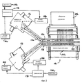
на фиг. 1 - в схематичном виде типичное устройство для сборки спиральных пружин известной конструкции;
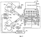
на фиг. 2 - в схематичном виде наподобие виду, показанному на фиг. 1, другое устройство для сборки спиральных пружин известной конструкции;
на фиг. 3 - в схематичном виде один из вариантов выполнения устройства для сборки спиральных пружин, выполненный в соответствии с принципами настоящего изобретения;
на фиг. 4 - в схематичном виде наподобие виду, показанному на фиг. 3, устройство для сборки спиральных пружин, выполненное согласно изобретению в альтернативном варианте;
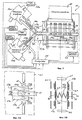
на фиг. 5 - в схематичном виде устройство для сборки спиральных пружин, выполненное в соответствии с принципами изобретения в еще одном варианте выполнения;
на фиг. 5A - вид по линии 5A-5A на фиг. 5;
на фиг. 5B - вид по линии 5B-5B на фиг. 5A;
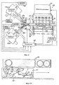
на фиг. 6 - в схематичном виде устройство для сборки спиральных пружин, выполненное в соответствии с принципами изобретения в еще одном варианте выполнения;
на фиг. 6A - вид по линии 6A-6A на фиг. 6;
на фиг. 7 - схематично экран дисплея контрольного интерфейса варианта выполнения, показанного на фиг. 3;
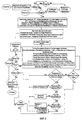
на фиг. 8 - блок-схема программы контроллера для работы в варианте выполнения, показанном на фиг. 3;
на фиг. 9 - подробная блок-схема работы подпрограммы вычислений программы, показанной на фиг. 8.List of drawings
These and other objects and advantages of the present invention will be more apparent from the following detailed description of preferred embodiments with reference to the drawings, in which:
in FIG. 1 is a schematic representation of a typical apparatus for assembling coil springs of known design;
in FIG. 2 is a diagrammatic view similar to that shown in FIG. 1, another device for assembling coil springs of known design;
in FIG. 3 is a schematic view of one embodiment of a device for assembling coil springs, made in accordance with the principles of the present invention;
in FIG. 4 is a schematic view similar to that shown in FIG. 3, an apparatus for assembling coil springs made in accordance with the invention in an alternative embodiment;
in FIG. 5 is a schematic view of a device for assembling coil springs, made in accordance with the principles of the invention in yet another embodiment;
in FIG. 5A is a view along line 5A-5A in FIG. 5;
in FIG. 5B is a view along line 5B-5B of FIG. 5A;
in FIG. 6 is a schematic view of a device for assembling coil springs, made in accordance with the principles of the invention in yet another embodiment;
in FIG. 6A is a view along line 6A-6A in FIG. 6;
in FIG. 7 is a schematic diagram of the display screen of the control interface of the embodiment shown in FIG. 3;
in FIG. 8 is a block diagram of a controller program for operation in the embodiment shown in FIG. 3;
in FIG. 9 is a detailed flowchart of the routine for computing the program shown in FIG. eight.
Подробное описание предпочтительных вариантов выполнения
На фиг. 1 схематично изображено одно устройство 10 известной конструкции для изготовления пружинных внутренних частей изделий. Одно такое устройство, например, описано в патенте США N 3386561. Такое устройство содержит устройство для изготовления пружин (или навивочное устройство) 11, производящее спиральные пружины 12 и подающее их последовательно к конвейеру 13. Конвейер 13 образован парой противолежащих бесконечных ремней 14 и 15, сжимающих пружины 12 и перемещающих пружины 12 при сохранении равных промежутков между ними к переносящему механизму 20. Конвейер 13 работает в шаговом ступенчатом режиме, с синхронизацией с периодическим изготовлением пружин 12 навивочным устройством 11. Обычно скоординированная работа конвейера 13 и навивочного устройства 11 обеспечивается с помощью привода 16 навивочного устройства 11, непосредственно связанного механической трансмиссией 17 с приводом 18 конвейера 13, причем оба привода 16 и 18 приводятся в действие через трансмиссию 17 от одного и того же двигателя 19.Detailed Description of Preferred Embodiments
In FIG. 1 schematically shows one
При обычной работе навивочное устройство 11 работает с максимальной производительностью до тех пор, пока заполненный ряд пружин 12 не будет подан на конвейер 13 к переносящему механизму 20. Когда заполненный ряд подается к переносящему механизму 20 посредством конвейера 13, захватное устройство переносящего механизма (не показано) одновременно захватывает все пружины 12 ряда и переносит их к сборочному устройству 24, где они объединяются вместе и присоединяются к пружинам соседних рядов пружин с образованием пружинной внутренней части изделия. Во время работы переносящего механизма 20 конвейер 13 и навивочное устройство 11 на мгновение останавливаются, в то время как пружины 12 переносятся от конвейера 13 в сборочное устройство 24. Когда захватное устройство отойдет от конвейера 13 на достаточное расстояние, чтобы не создавать помех в его работе, работа навивочного устройства 11 и конвейера 13 продолжится. In normal operation, the winding
Одним из первых выявляемых недостатков конструкции, показанной на фиг. 1, является то, что навивочное устройство производит пружины 12 в темпе более медленном, чем тот, в котором переносящая установка 20 и сборочное устройство 24 могут их снимать с конвейера 13 и собирать. Для преодоления этого недостатка было разработано устройство 10a также известной конструкции, показанное на фиг. 2. Устройство 10a, показанное на фиг. 2, содержит пару навивочных устройств 11a и 11b, которые соответственно образуют два ряда пружин 12a и 12b, подающихся соответственно по двум параллельным направляющим к паре конвейеров 13a и 13b. В этом варианте выполнения предусмотрен модифицированный механизм 20a переноса с захватным устройством (не показано), которое снимает ряды пружин 12a и 12b попеременно с соответствующих конвейеров 13a и 13b и подает их к сборочному устройству 24. Такое устройство 10a описано в патенте США N 4413659. Конвейеры 13a и 13b работают в шаговом режиме, с синхронизацией с периодическим производством пружин 12a и 12b соответствующими навивочными устройствами 11а и 11b. Обычно скоординированная работа конвейеров 13a, 13b и навивочных устройств 11a, 11b обеспечивается с помощью соответствующих приводов 16a и 16b навивочных устройств, непосредственно связанных соответствующей механической трансмиссией 17a и 17b с приводами 18a и 18b конвейеров соответственно. Оба комплекта приводов 16a и 18a и 16b и 18b через трансмиссии 17a и 17b соответственно связаны с приводными двигателями 19a и 19b. One of the first identified design flaws shown in FIG. 1, the winding device produces
При обычной работе устройство 10a работает с его максимальной производительностью благодаря работе каждого из навивочных устройств 11a и 11b и конвейеров 13a и 13b, до тех пор пока каждый или один из двух конвейеров не подаст заполненный ряд пружин 12a или 12b к переносящему механизму 20a. Когда заполненный ряд подается к переносящему механизму 20a посредством одного из конвейеров, например 13a, захватное устройство переносящего механизма (не показано) располагается для одновременного захвата всех пружин 12a ряда и переносит их к сборочному устройству 24a, где они объединяются вместе и присоединяются к пружинам соседних рядов с образованием пружинной внутренней части изделия. Во время работы переносящего механизма 20a может потребоваться на мгновение остановка конвейера 13a, а в некоторых ситуациях и даже навивочного устройства 11a, в то время как пружины 12a переносятся от конвейера 13a в сборочное устройство 24a. Во многих производствах остановка навивочного устройства нежелательна, она может повлиять на качество пружин и остановок следует избегать. Когда захватное устройство достаточно очистит конвейер 13a, так чтобы не создавать помех в его работе, работа навивочного устройства 11а и конвейера 13a продолжится. Затем, когда следующий заполненный ряд подается к переносящему механизму 20a другим конвейером 13b, захватное устройство меняет положение с тем, чтобы одновременно захватить все пружины 12b ряда и перенести их к сборочному устройству 24a, где они также стягиваются вместе и присоединяются к пружинам соседнего ряда пружин 12a с образованием пружинной внутренней части изделия. Во время работы переносящего механизма 20a по снятию пружин 12b с конвейера 13b конвейер 13b и навивочное устройство 11b аналогичным образом на мгновение останавливаются. Когда захватное устройство отойдет от конвейера 13 на достаточное расстояние, чтобы не создавать помех в его работе, работа навивочного устройства 11b и конвейера 13b может возобновиться. In normal operation, the device 10a operates at its maximum productivity due to the operation of each of the winding
В обоих вышеописанных известных устройствах 10 и 10a расстояние между пружинами 12 на конвейере 13 для подачи к переносящему механизму 20a определяется работой навивочного устройства 11, подающего пружины с равными зазорами между ними на конвейере 13. Однако согласно настоящему изобретению предложены устройства, выполненные одновременно с возможностью расположения пружин на конвейере с различными и программируемыми интервалами и также с возможностью программируемого чередования пружин различных форм и типов на конвейерах. Четыре варианта выполнения таких устройств показаны на чертежах фиг. 3 - 6, описанных ниже. In both of the above-described
Как показано на фиг. 3, предложено устройство 30 для изготовления пружинных внутренних частей изделий, выполненное согласно настоящему изобретению, содержащее устройство для изготовления пружин (называемое также навивочным устройством) 31, выполненное аналогично навивочным устройствам 11, упомянутым выше, работающее для изготовления отдельных спиральных пружин 32. Эти спиральные пружины 32 изготавливаются по одной за каждый рабочий цикл устройства 31 для изготовления пружин и подаются на конвейер 33, который, подобно конвейерам 13, описанным выше, выполнен в виде конвейера с противолежащими ремнями, последовательно подающего ряд пружин 32 к переносящей установке (называемой также переносящим механизмом) для одновременного переноса пружинных рядов с конвейера 33 к сборочному устройству 35 для сборки во внутренней части изделия. Подходящие пружинные устройства 31 для изготовления пружин для использования с устройством, выполненным согласно изобретению, известны, одно такое навивочное устройство описано в патенте Великобритании N 1327795, озаглавленном "Усовершенствования, относящиеся к машинам для изготовления полос из сжатых пружин из проволоки, например, для вставки в мягкую мебель". Конвейер 33, переносящий механизм 34 и сборочное устройство 35, подходящие для использования в устройстве, выполненном согласно изобретению, упомянуты выше и описаны в патентах США N 3386561 и N 3774652, и которые включаются в настоящее описание путем ссылки на них. Концепция настоящего изобретения может быть использована или приспособлена для использования в машинах тех типов, что описаны во всех этих объединенных упомянутых патентах. As shown in FIG. 3, there is provided a
В отличие от конвейера 13, описанного выше, конвейер 33 не связан непосредственно с устройством 31 для изготовления пружин, но выполнен с возможностью работы отдельно от этого устройства 31, предпочтительно с отдельным приводом от серводвигателя 36. Серводвигатель 36 предпочтительно выполнен в виде шагового двигателя, обеспечивающего шаговое перемещение конвейера 33 в ответ на сигналы, например в форме импульсов, на выходе из программируемого контроллера 37. Фиксированный шаг приращения мал и может составлять, например, 1/500 оборота приводного колеса для каждого полученного импульса, тем самым обеспечивая точное управление движением конвейера 33. Контроллер 37 также синхронизирует перемещение конвейера 33 с последующей работой устройства 31 для изготовления пружин, соединенного со своим приводом 38, так что изготовленная пружина 32 может быть точно установлена на входном конце конвейера 33 с точной установкой расстояния между каждой помещенной на конвейер 33 пружиной 32 и пружиной 32, помещенной в этот конвейер ранее. Unlike the
Работая отдельно под управлением контроллера 37, устройство 31 для изготовления пружин производит ряд пружин 32 и помещает его на конвейер 33 с интервалами, определенными контроллером 37, так как он координирует перемещение конвейера 33. Промежутки между соседними пружинами 32 ряда определяются в соответствии с программой контроллера 37. Предпочтительно всякий раз, когда сделано меньшее количество пружин, чем общее количество, требуемое в соответствии с выполняемой работой, устройство 31 для изготовления пружин будет изготавливать пружину 32 и, если контроллер 37 сделает вывод о том, что конвейер 33 находится в положении для приема изготовленной пружины 32, устройство 31 для изготовления пружин подаст изготовленную пружину 32 на конвейер 33, и навивочное устройство переходит к изготовлению следующей пружины, если еще одна пружина требуется в рамках выполняемой работы. Если конвейер 33 не находится в таком положении для приема пружины 32, навивочное устройство останавливается в ожидании сигнала от контроллера о нужном положении конвейера 33. Как только пружина 32 подается устройством 31 для изготовления пружин на конвейер 33, датчик 39, который может содержаться в устройстве, может направить сигнал о том, что конвейер 33 теперь может переместиться на шаг. Таким образом, конвейер никогда не переместится на шаг без наличия пружины, отсутствие которой могло бы привести к пробелу в готовом ряду пружин. Working separately under the control of the
Как только ряд пружин 32 установлен на конвейере 33, конвейер 33 перемещает ряд в переносящую установку 40, содержащую переносящий механизм 34, который может быть выполнен в виде механизма 20 известной конструкции, показанной на фиг. 1, или в виде другого подходящего переносящего механизма. Когда один законченный ряд пружин 32 помещен на конвейере 33, дальний в направлении движения конец ряда будет обычно заходить в переносящую установку 40. Устройство 31 для изготовления пружин может затем продолжить работу под управлением контроллера 37 для изготовления пружин следующего ряда, которые будут располагаться на конвейере 33 в той его части, которая примыкает к навивочному устройству 31, по мере того как конвейер будет продолжать шаговое перемещение в ответ на сигналы от контроллера 37. As soon as the row of springs 32 is mounted on the
Когда законченный ряд пружин поступит в переносящую установку 40 и будет готов для переноса механизмом к сборочному устройству 35, которое может быть выполнено наподобие сборочного устройства 24 устройств 10 и 10a известных конструкций, описанных в связи с чертежами фиг. 1 и 2 выше, контроллер 37 на мгновение останавливает конвейер 33, в то время как переносящий механизм 34 в переносящей установке захватывает пружины 32 на конвейере 33 для их переноса к сборочному устройству 35. Далее, в некоторых производственных ситуациях может быть необходимо кратковременно остановить также и устройство 31 для изготовления пружин, даже если этого следует обычно избегать. Контроллер 37 может быть запрограммирован сохранять последовательности импульсов, посланных шаговому двигателю 36, или считать импульсы обратной связи от шагового двигателя 36 или от какого-либо другого решающего устройства или декодера 46, соединенного с ведущим или направляющим шкивом привода ремней конвейера 33 и таким образом вычислять, когда ряд изготовленных пружин находится в положении для того, чтобы быть перенесенным переносящим механизмом переносящей установки 40. Далее, контроллер 37 может работать на основе сигнала от датчика 44 для определения момента, когда ряд изготовленных пружин должным образом расположен у переносящей установки 40. Если контроллер 37 использует сигналы шагового перемещения конвейера 33, желательно, чтобы ремни конвейера 33 были выполнены в виде нерастяжимых армированных синхронизирующих ремней типа зубчатых ремней, которые могут иметь жесткую, без проскальзывания, связь с приводными зубчатыми колесами; или альтернативно, сигнал перемещения конвейера может сниматься с зубчатых колес при условии отсутствия проскальзывания между колесами и ремнями. When the finished row of springs enters the
Аналогично контроллер 37 может управлять цикличной работой устройства 31 для изготовления пружин путем слежения за пошаговым перемещением конвейера 33 за счет использования регистров памяти, в которых хранится постоянно обновляемая информация о положениях пружин 32 на конвейере 33. В дополнение, или в качестве альтернативы, контроллер 37 может сохранять информацию о последовательности пружин в ряду, подаваемых на конвейер 33, и может полностью основываться на получаемом сигнале обратной связи от датчика 46, отслеживающего положение конвейера 33. Similarly, the
На фиг. 4 показан вариант выполнения устройства 30a, выполненного согласно изобретению, содержащего две группы навивочных устройств 31a, 31b и конвейеры 33a, 33b такого типа, как показан в варианте выполнения на фиг. 3 как устройство 31 для изготовления пружин и конвейер 33, организованные в виде двух линий А и В по изготовлению и доставке пружин. Конвейеры 33a и 33b отличаются от конвейера 33 таким же образом, как конвейеры 13a и 13b устройства, показанного на фиг. 2, отличаются от конвейера 13 устройства, показанного на фиг. 1, как пояснено и подробно описано в патенте США N 4,413,659, который включается в настоящее описание путем ссылки на него. Совместно с конвейерами 33a и 33b работает переносящая установка 40a, переносящая пружины попеременно от конвейеров 33a и 33b к сборочному устройству 35a. In FIG. 4 shows an embodiment of a
В одном варианте выполнения устройство 30a использует два устройства 31a и 31b для изготовления пружин, связанных приводами 38a и 38b для производства идентичных пружин 32 для более быстрой подачи пружин 32 к переносящей установке 40a и сборочному устройству 35a для ускорения операции сборки, что явилось задачей разработки известной конструкции, показанной на фиг. 2. В таком варианте выполнения переносящий механизм 34a переносящей установки 40a получает ряды пружин попеременно от конвейеров 33a и 33b. Каждая группа, состоящая из навивочного устройства и конвейера, то есть устройство 31 для изготовления пружин и конвейер 33a и устройство 31b для изготовления пружин и конвейер 33b управляются аналогичным образом как группа, состоящая из устройства 31 для изготовления пружин и конвейера 33 в варианте выполнения, показанном на фиг. 3. При этом каждый из конвейеров 33a и 33b снабжен приводом от шагового двигателя 36a и 36b с управлением обоих двигателей от общего контроллера 37a, обеспечивающего управление обоими устройствами 31a, 31b и обоими шаговыми двигателями 36a, 36b, как было описано в связи с вариантом выполнения, показанном на фиг. 3, для обеспечения программируемых промежутков между пружинами 32a, 32b вдоль соответствующих линий A и B. Контроллер 37a, показанный на фиг. 4, таким образом выполняет функции двух раздельных контроллеров 37 типа, показанного на фиг. 3, и кроме того, координирует работу двух линий A и B с попеременной работой переносящего механизма переносящей установки 40a. Эта координация включает раздельный учет прибытия рядов пружин 32 от двух линий в заданное положение в переносящей установке 40a и попеременную кратковременную остановку двух линий синхронно с попеременным переносом пружин от соответствующих линий к сборочному устройству 35a. Во всех других отношениях две линии A и B могут быть выполнены идентичными и каждая имеет те же параметры, что и одинарная линия, показанная на фиг. 3 в вышеописанном варианте выполнения, включая соответствующие датчики 39a, 39b, 44a, 44b и 46a, 46b в соответствии с функцией и местоположением каждой линии A или B относительно датчиков 39, 44 и 46 на фиг. 3. In one embodiment,
В предпочтительном варианте выполнения устройства 30a, показанного на фиг. 4, линии A и B настроены на производство различных типов пружин 32a и 32b, например, пружин различных размеров, прочности и жесткости. Такие различные пружины 32a, 32b могут требоваться в конструкции пружинной внутренней части изделия, например, при расположении более жестких пружин (например, 32b) по периферии, а более мягких пружин (например, 32a) - в центральной части пружинной внутренней части изделия. В таком устройстве 30a переносящий механизм 34a у переносящей установки 40a работает совместно со сборочным устройством 35a, с подачей пружин 32a и 32b к сборочному устройству 35a в каждом цикле сборочного устройства 35a, так что пружины обоих типов могут быть объединены в один и тот же ряд в собираемой внутренней части изделия. Для обеспечения этого промежутки между более мягкими пружинами 32a и более жесткими 32b, когда их ряды находятся в положении у переносящей установки 40a для переноса к сборочному устройству 35a, располагаются в соответствии с программируемой схемой расположения контроллера 37a, то есть обусловлены синхронизацией промежутков пружин 32a и 32b на соответствующих конвейерах 33a и 33b устройствами 31a и 31b. In a preferred embodiment of the
В еще одном варианте выполнения изобретения, показанном на фиг. 5, устройство 50 предназначено для производства пружинных внутренних частей изделий, содержащих пружины более чем одного типа, как во втором варианте выполнения 30a, показанном на фиг. 4. Устройство 50 отличается от устройства 30a тем, что устройство 50 снабжено переносящим конвейером 51, образованным из одной пары бесконечных ремней, проходящих через переносящую установку 52. Конвейер 51 имеет привод от шагового двигателя 53. Переносящая установка 52 отличается от переносящей установки 40a в варианте, показанном на фиг. 4, тем, что подача пружин 54a и 54b различных типов для переноса к сборочному устройству 55 осуществляется с одного конвейера 51, а не с двух конвейеров 33a и 33b, показанных в варианте на фиг. 4. Устройство 50, показанное на фиг. 5, содержит дополнительно устройства для изготовления пружин 56a и 56b, отличающееся от устройств для изготовления пружин 15 (навивочных устройств) 31a и 31b варианта на фиг. 4 тем, что на выходах устройств расположены устройства подачи пружин, представляющие собой, например, разгрузочные конвейеры 57a и 57b для прерывистой подачи пружин, изготовленных устройствами 56a и 56b, ко входному концу переносящего конвейера 51. Устройства для изготовления пружин 56a и 56b производят пружины 54a, 54b, которые могут иметь отличия в размере или жесткости, как было указано в примере с более мягкими пружинами 32a и с более жесткими 32b, как в варианте выполнения на фиг. 4. Каждый конвейер 57a и 57b выполнен с возможностью иметь привод, независимый от работы устройств 56a и 56b также посредством отдельных серводвигателей 58a и 58b, которые могут быть теми же самыми, что и шаговые двигатели 36a и 36b в варианте выполнения на фиг.4. Серводвигатели 58a и 58b, устройства для изготовления пружин 56a и 56b, переносящая установка 52 и сборочное устройство 55 управляются контроллером 59. In yet another embodiment of the invention shown in FIG. 5, the
Вариант выполнения, показанный на фиг. 5, также содержит перевалочную установку 65, в которую входят выходные концы конвейеров 57a и 57b, причем один, например 57b, располагается над другим, 57a. Между этими выходными концами конвейеров 57a и 57b у перевалочной установки 65 расположен входной конец переносящего конвейера 51, как показано на фиг. 5A и 5B. В перевалочной установке 65 может быть использован любой из разнообразных механизмов для избирательного перемещения пружин 54a и 54b от соответствующих конвейеров 57a и 57b на конвейер 51. Такой механизм может содержать пару толкателей 66 и 67 с электромагнитным или пневматическим приводом, которые, включаясь в работу по сигналу от контроллера 59, выдвигаются к соответствующим пружинам 54a, 54b на конвейере 57a, 57b для перемещения пружин в вертикальном направлении, вверх или вниз, на входной конец конвейера 51. Устройство содержит направляющие пластины 68 и 69, выполненные из нержавеющей стали, проходящие от зоны позади переднего пролета ремней конвейеров 57a и 57b к переднему пролету ремней конвейера 51 для направления пружин 54a, 54b на конвейер 51. Направляющие пластины 68 и 69 имеют горизонтальные концевые секции 71 для захвата концов пружин, когда они доставляются толкателями 66 и 67 на переносящий конвейер 51. Задняя пластина 63 надежно удерживает ремни конвейера 51 в положении близко к конвейерным концевым секциям 71 для предотвращения захвата пружин между пластинами 68 и 69 и ремнями конвейера 51. The embodiment shown in FIG. 5 also includes a
При работе, когда на конвейерах 51, 57a и 57b нет пружин, программа контроллера 59 начинает инициализацию циклов устройств 56a и 56b для изготовления пружин путем посылки включающих импульсов навивочным устройствам. По завершении каждого цикла навивочных устройств 56a и 56b указанные устройства для изготовления пружин подают изготовленные пружины 5a, 54b на входной конец соответствующего конвейера 57a, 57b, что вызывает подачу сигнала обратной связи на контроллер 59, например, от датчика 72 на входном конце конвейера 57a, 57b или от датчика на самом механизме подачи готовых пружин устройства для изготовления пружин. По получении такого сигнала обратной связи контроллер 59 вначале проверяет, заполнен ли соответствующий конвейер 57a, 57b до отказа или содержит пружину, занимающую положение у выходного конца конвейера 57a, 57b рядом с толкателем 66, 67 у перевалочной установки 65. Если установлено, что ни одно из этих условий не выполняется, и следовательно, перемещение конвейера на один шаг не вызовет продвижение пружины мимо перевалочной установки 65, посылается серия импульсов соответствующему серводвигателю 58a, 58b для продвижения соответствующего конвейера 57a, 57b на один шаг в сторону его выходного конца на точное расстояние, требуемое для перемещения изготовленной пружины 5a, 54b и освобождения места на входном конце конвейера 57a или 57b для следующей изготовленной пружины. In operation, when there are no springs on the
Тем временем контроллер 59 выполняет программу-"шаблон", устанавливающую порядок и расположение пружин на конвейере 51. В примере, показанном на фиг. 5, фиксированное количество более жестких пружин 54b предназначено для сборки на концах каждого ряда пружин, в то время как комплекты менее жестких пружин 54a должны быть расположены между более жесткими пружинами 54b. Контроллер 59 посылает управляющий сигнал перевалочной установке 65 и конвейерам 51, 57a и 57b, благодаря чему пружины 54a, 54b от устройства 56a, 56b устанавливаются на конвейере 51 с надлежащими зазорами и в нужном порядке для подачи к переносящей установке 52 в соответствии с желаемой схемой расположения пружин. Для того чтобы этого достичь, контроллер 59 запоминает положение конвейера 51, а также всех пружин 54a и 54b, помещенных на нем, затем перемещает конвейеры 51, 57a и 57b на один шаг и включает толкатели 66, 25 67 в переносящей установке 65 для последовательного добавления пружин 54a, 54b в должной последовательности и с должными зазорами на конвейер 51. In the meantime, the
Когда работа началась, контроллер 59 будет двигать конвейер 51 до тех пор, пока он не освободится. Затем контроллер 59 включает счетчик в памяти контроллера с числом, соответствующим начальному положению конвейера. Отсчет, заносящийся в память, - это предпочтительно отсчет импульсов шагового двигателя или импульсов обратной связи от цифрового преобразователя устройства на зубчатом колесе, движущемся вместе с зубчатыми ремнями конвейера 51. Счетчик может содержать некоторое соответствующее представление расстояния от опорной точки на конвейере 51 до одной или большего количества точек на конвейере 51, например, точки 73 совмещения с переносящей установкой 52 и/или точки 74 загрузки пружин и перевалочной установки 65, у которой пружины загружаются на конвейер 51. Точки 73 и 74 могут в общем случае рассматриваться как пересечение конвейера 51 с плоскостями, перпендикулярными плоскости конвейера 51. When work has begun, the
В предпочтительном варианте, как только в контроллере 59 будут установлены начальные значения и работа началась, контроллер 59 проверяет, находится ли пружина 54b в точке 75 выгрузки у выходного конца конвейера 57b в перевалочной установке 65, которая расположена прямо над загрузочной точкой 74. Если нет, то конвейер 57b перемещается в результате действия импульсов, посланных контроллером 59 шаговому двигателю 58b, до тех пор пока пружина 54b не достигнет положения 75 выгрузки. Когда пружина находится в этом положении выгрузки, конвейер 57b останавливается и остается в остановленном положении до тех пор, пока пружина 54b в точке 75 не будет снята и помещена на конвейер 51. В то время как конвейер 57b остановлен, операции, требующие перемещения конвейера 57b, например, выведение пружин с устройства 56b, упомянутое выше, должно также быть остановлено, и контроллер 59 обеспечивает остановку таких операций путем посылки соответствующих сигналов к устройству 56b. In a preferred embodiment, as soon as the initial values are set in the
Когда конвейер 57b останавливают с пружиной 54b в положении 75 выгрузки, толкатель 67 включается контроллером 59 для переноса пружины 54b вниз от конвейера 57b в свое положение на переносящем конвейере 51. Затем, когда толкатель 67 отходит назад и конвейер 51 освобождается, конвейер 51 перемещается посредством посылки импульсов от контроллера 59 к шаговому двигателю 53 для продвижения конвейера 51 на точное требуемое запрограммированное расстояние между центрами первых двух пружин 54b схемы расположения. Это определяет положение конвейера 51, в котором будет получена следующая пружина 54b в положении 74 загрузки на перевалочной установке 65. Затем при условии, что толкатель 67 отведен от конвейера 57b, посредством вышеописанной процедуры пружина 54b доставляется в положение 75 выгрузки на конвейере 57b, и толкатель 67 включается вновь по сигналу от контроллера 59 и толкает вторую пружину 54b от положения 75 выгрузки на конвейере 57b к точке 74 на конвейере 51. When the conveyor 57b is stopped with the
Когда две более жесткие пружины 54b доставлены на конвейер 51, контроллер 59 обеспечивает аналогичным образом подачу серии пружин 54a от устройства 56a для изготовления пружин на конвейер 51 с зазорами, требуемыми запрограммированной схемой расположения пружин в изделии в контроллере 59. Для выполнения этого контроллер 59 проверяет, находится ли пружина 54a в точке 76 выгрузки у выходного конца конвейера 57a в перевалочной установке 65, расположенной прямо под загрузочной точкой 74 конвейера 51. Если нет, то конвейер 57a продвигается благодаря посылке импульсов шаговому двигателю 58a от контроллера 59, до тех пор пока пружина 54a не будет доставлена в указанное положение 76 выгрузки. Когда пружина 54a находится в этом положении 76 выгрузки, конвейер 57a останавливается и будет стоять до тех пор, пока пружина 54a в положении 76 не будет удалена для загрузки ее на конвейер 51. В то время как конвейер 57a остановлен, операции, требующие перемещения конвейера 57a, например, выведение пружин с устройства для изготовления пружин 56a, упомянутое выше, должно также быть остановлено, и контроллер 59 обеспечивает остановку таких операций путем посылки соответствующих сигналов к навивочному устройству 56a. When two
Датчики (не показаны) включены в состав перевалочной установки 65 для того, чтобы гарантировать, что у загрузочной точки 74 переносящего конвейера 51 присутствует пружина, прежде чем конвейер 51 продвинется. Это предотвращает образование "пробелов" в ряду пружин таким же образом, как это делают датчики 39 вариантов выполнения 30 и 30a, показанных на фиг. 3 и 4. Подобные датчики также имеются у точек 75, 76 выгрузки для предотвращения продвижения пружин дальше указанных точек по конвейерам 57a, 57b. Эти датчики делают наличие датчиков 72 необязательным для предотвращения пробелов в рядах пружин, так как такие пробелы могут быть компенсированы посредством работы конвейеров 57a, 57b в продвижении пружин к точкам 75, 76 выгрузки, хотя датчики 72 облегчают работу навивочных устройств 56a, 56b. Sensors (not shown) are included in the
Когда конвейер 57a остановлен с пружиной 54a в положении 76 выгрузки, толкатель 66 включается посредством контроллера 59 для переноса пружины 54a вверх от конвейера 57a в положение 74 на переносящем конвейере 51. Затем, когда толкатель 66 возвращается назад и отходит от конвейера 51, конвейер 51 перемещается благодаря посылке импульсов от контроллера 59 к шаговому двигателю 53 для продвижения конвейера 51 на точную величину программируемого расстояния, требуемого между центрами последней загруженной пружины 54a и следующей пружиной, согласно схеме расположения. Это приводит конвейер 51 в положение, в котором на него поступает следующая из пружин 54a в положении 74 загрузки у перевалочной установки 65. Затем, при условии, что толкатель 66 отошел от конвейера 57a, посредством вышеописанной процедуры пружина 54a доставляется в положение 76 выгрузки на конвейере 57a, и толкатель 66 включается вновь по сигналу от контроллера 59 и толкает вторую пружину 54a от точки 76 на конвейере 57a к точке 74 на конвейере 51. When the
Когда последняя из пружин 54a, требуемых в соответствии со схемой расположения, размещена на конвейере 51, следующие две подлежащие загрузке пружины 54b загружаются последовательно на конвейер 51 под управлением контроллера, выполняющего те же вышеописанные процедуры. Затем, когда полный ряд пружин подан на конвейер 51, контроллер 59 посылает шаговому двигателю 53 соответствующее количество импульсов, требуемых для перемещения первой из пружин 54b, размещенных на конвейере 51 в точке 73 совмещения в переносящей установке 52, в результате чего конвейер 51 останавливается. Когда конвейер 51 останавливается, контроллер 59 посылает сигнал переносящей установке на старт цикла переноса, в процессе которого ряд пружин 54a, 54b перемещается от конвейера 51 к сборочному устройству 55. Одновременно контроллер может начать посредством загрузки предусмотренной схемой расположения первой пружины 54b процедуру размещения схемы расположения с пружинами на конвейере 51. When the last of the
Еще один вариант выполнения, похожий на вариант, показанный на фиг. 5, но обеспечивающий более быструю работу и более эффективное использование навивочных устройств 56a, 56b - это устройство 80, показанное на фиг. 6. В варианте 15 выполнения, показанном на фиг. 6, конвейеры 57a и 57b заменены конвейерами 81a и 81b, каждый их которых выполнен из двух частей, содержащих конвейеры 82, 83 перевалочной установки и накопительные конвейеры 85, 86. Another embodiment similar to that shown in FIG. 5, but providing faster operation and more efficient use of the winding
Конвейеры 82, 83 перевалочной установки соответственно выполнены в виде укороченных вариантов конвейеров 57a, 57b варианта выполнения на фиг. 5. Конвейеры 82, 83 проходят от точек 88, 89 поставки пружин, и каждый работает от управляющего сигнала контроллера 90, продвигая одну пружину от точки 88 или 89 поставки пружины к соответствующим точкам 75, 76 выгрузки. Управляющий сигнал генерируется только при условии, что пружина 54a, 54b присутствует у соответствующей точки 88, 89 поставки пружины, нет пружин у соответствующих точек 76, 75 выгрузки и соответствующий толкатель 66, 67 отведен от конвейера 82, 83. Таким образом, конвейер 82, 83 будет нести лишь одну пружину в данный момент времени и может быть включен посредством такого управляющего сигнала, всякий раз когда такие условия выполняются, так что пружина 54a, 54b доставляется к соответствующей точке 76, 75 выгрузки, как только указанная пружина выталкивается от этой точки к точке 74 переноса переносящего конвейера 51. The
Накопительные конвейеры 85, 86 предназначены для обеспечения работы устройств 56a, 56b с полной производительностью по меньшей мере до тех пор, пока накопительные конвейеры 85, 86 не будут заполнены пружинами 54a, 54b. Накопительные конвейеры 85, 86 выполнены в виде конвейеров с противолежащими сжимающими ремнями наподобие конвейеров 57a и 57b варианта на фиг. 5, но каждый из них содержит также механизм 92 устранения зазоров, который работает по команде от контроллера 90, сдвигая каждую пружину 54a, 54b, изготовленную навивочным устройством 56a, 56b, вперед между ремнями накопительных конвейеров 85, 86, до тех пор пока они не займут положение рядом с предыдущей изготовленной пружиной 54a, 54b. Механизм 92 содержит крюк 93, который несет каретка 94, совершающая возвратно-поступательные движения с переменной величиной хода и имеющая предпочтительно привод от электродвигателя, которая движется в пазах направляющих или рельсов (не показаны) и перемещается пневматическим цилиндром 95 вверх от каретки 94 за каждую пружину 54a, 54b, подающуюся к входному концу конвейера 85, 86 от устройства для изготовления пружин 56a, 56b. Крюк 93 захватывает последнюю поданную пружину и продвигает ее вдоль между ремнями соответствующего конвейера 85, 86 посредством перемещения каретки 94 в сторону выходного конца конвейера, до тех пор пока не исчезнет зазор между данной и предыдущей пружинами, что регистрируется датчиком 96 на каретке 94. Ремни конвейеров 85, 86 имеют привод от серводвигателей 97, 98 соответственно предпочтительно шагового типа, работающих по команде от контроллера 90, всякий раз когда соответствующий разгрузочный конвейер 82, 83 останавливается и отсутствует пружина 54a, 54b в соответствующей точке 88, 89 поставки пружины. Благодаря такой конструкции достигается максимальная общая скорость работы устройства. The accumulation conveyors 85, 86 are designed to ensure the operation of the
Контроллеры 37, 37a, 59 и 90 в вариантах выполнения изобретения, показанных соответственно на фиг. 3, 4, 5 и 6, могут быть выполнены в любой из ряда форм, одна из которых описана на фиг. 7 и содержит главным образом программируемый многоцелевой цифровой компьютер 100, основанный на микропроцессоре, снабженный соответствующими внутренними и внешними интерфейсами и драйверами, которые на фиг. 7 изображены в общем виде как интерфейс 101 для связи с двигателями и датчиками устройств 30, 30a, 50 или 80 соответствующих показанных вариантов выполнения. Такой компьютер 100 может быть оборудован клавиатурой (keyboard) 102 и устройством 103 управления позицией, например мышью или трекболом, для ввода оператором данных и команд, и обычным дисплеем 105 компьютера для передачи информации о статусе машины и программы оператору. Такой контроллер может быть запрограммирован посредством любого языка программирования, например, с помощью Microsoft Visual BasicTM, на котором могут быть написаны как программа работы устройства, так и программа интерфейса для оператора. Однако для крупномасштабного производства таких устройств предпочтительно использование промышленных контроллеров с программируемой логикой, запрограммированных в обычной многозвенной логической схеме или на другом языке вместо многоцелевого микрокомпьютера 100, описанного здесь, в особенности для управления рабочим циклом устройств 30, 30a, 50 и 80. В дополнение предпочтительно использование настраиваемого сенсорного экрана для интерфейса оператора. Для целей описания работы контроллера программа описана вначале в связи с простейшим из показанных вариантов выполнения, изображенным на фиг. 3.
Структура данных для использования с предпочтительной управляющей программой компьютера 100 может быть понята со ссылкой на дисплей 105, изображенный на фиг. 7, на котором средствами экранной графики изображено поле заголовка окна и меню 106, окно 107 установки параметров и рабочее окно 108. Меню 106 содержит разворачиваемое меню Windows, обеспечивающее выход в окно установки 107 и рабочее окно 108. В окне 107 установки оператор может просматривать, добавлять или изменять содержание любой из четырех таблиц баз данных, каждая из которых отображена в своем окне или в рамке. Эти окна содержат окно 111 определения заказа, окно 112 определения модуля, окно 113 определения ряда и окно 114 определения пружины. The data structure for use with the preferred control program of the
Окно 111 определения заказа обеспечивает доступ к таблице базы данных заказов, содержащей множество записей, каждая из которых идентифицирована уникальным номером заказа, занесенным в поле "Номер Заказа" (Job No.) и отображаемым в текстовой рамке 115 "Номер Заказа" (Job No.) в окне 111. Номер заказа автоматически записывается в своем поле, всякий раз когда оператор нажимает кнопку 116 команды "Новый Заказ" (New Job) с помощью устройства 103 управления позицией или с клавиатуры 102. Когда выбирается команда "Новый Заказ" (New Job), в базу данных заказов добавляется новая запись, в поле "Номер Заказа" которой заносится следующий по порядку номер, и в дополнение в поле записи "Ввод Даты" (Entry Date) загружается текущая дата, которая отображается в текстовой рамке 117 "Ввод Даты" (Entry Date) окна 111. Оператор задает новое задание или заказ путем занесения в текстовой рамке 118 данных "Описание Заказа" (Job Description), предназначенных для занесения информации пользователя. Оператор также вводит уникальный "Тип Модуля" (Unit Type) в текстовую рамку 119 "Тип Модуля" (Unit Type), отображающую поле "Тип Модуля" в записи. Когда оператор вводит "Тип Модуля", соответствующая информация от связанных баз данных появляется в окнах 112-114 типа модуля, типа ряда и определения пружины соответственно. Всякий раз, когда поле в окне 111 определения заказа не заполнено, записи для всех типов модуля, рядов и пружин выводятся в соответствующих определяющих окнах 112, 113, 114. Окно 112 типа модуля может быть прокручено оператором до тех пор, пока не будет найдено желаемое значение "Тип Модуля". Щелчком мыши на желаемом значении "Тип Модуля" в окне 112 определения модуля выбранный "Тип Модуля" загружается в имеющуюся текстовую рамку 119 "Тип Модуля" окна 111 определения заказа. Оператор может аналогичным образом ввести в текстовую рамку 120 "Количество Модулей" (Quantity) общее количество таких модулей выбранного "Типа Модуля", которые должны быть изготовлены в рамках выполнения заказа. Оператор может вместо этого выбрать "Количество Модулей = 0", что устанавливает в заказе неопределенное количество модулей выбранного "Типа Модуля", которые должны быть собраны, до тех пор пока оператор своей командой не остановит выполнение работы. Window 111 of the order definition provides access to the table of the database of orders containing many records, each of which is identified by a unique order number entered in the field "Order No." (Job No.) and displayed in the text box 115 "Order No." (Job No. ) in window 111. The order number is automatically recorded in its field whenever the operator presses the
В дополнение одно или большее количество других полей данных могут быть предусмотрены и отображены в окне 111 заказа, например, поля данных "Дата Выполнения" и/или "Время Выполнения" (Run date/time), отображающие время и дату выполнения заказа. Отсутствие информации в этих полях может быть использовано для отображения того, что работа не была выполнена. Оператор может также просмотреть незавершенные заказы путем использования имеющегося блока 121 управления данными. Интерфейс может быть запрограммирован так, что всякий раз, когда содержимое рамки 115 "Номер Заказа" (Job No.) меняется с помощью блока 121 управления данными или путем ввода данных нового заказа, кнопка 122 команды "Выбор" (Select), которая ранее была заблокирована, становится активной для предоставления оператору возможности выбрать заказ для выполнения. Далее всякий раз, когда работа останавливается в процессе выполнения, запись переписывается с заменой поля "Количество Модулей" фактическим количеством изготовленных модулей, и оператору предоставляется выбор либо автоматически ввести новый номер заказа, либо отменить выполнение оставшейся части заказа. Окно 111 также содержит кнопку 123 команды "Отобразить" (Display), включение которой открывает временное окно (не показано) для просмотра данных о всех завершенных заказах базы данных. In addition, one or more other data fields may be provided and displayed in the order window 111, for example, the “Run Date” and / or “Run Date / time” data fields displaying the time and date the order was completed. The lack of information in these fields can be used to indicate that the work has not been completed. The operator can also view unfinished orders by using the existing data management unit 121. The interface can be programmed so that whenever the contents of frame 115 “Job No.” is changed using data management unit 121 or by entering new order data, the Select command button 122, which was previously blocked, becomes active to provide the operator with the opportunity to select an order for execution. Further, whenever work stops during execution, the record is overwritten with the “Number of Modules” field replaced by the actual number of manufactured modules, and the operator is given the choice to either automatically enter a new order number or cancel the remaining part of the order. Window 111 also contains a button 123 of the "Display" command, the inclusion of which opens a temporary window (not shown) for viewing data on all completed database orders.
Таблица базы данных модулей, отображенная в окне 112 определения модуля, содержит информацию, определяющую конфигурации различных модулей, которые могут быть изготовлены. Для каждого значения "Тип Модуля" (Unit Type) таблица базы данных модулей содержит множество записей, имеющих те же данные "Тип Модуля" в поле "Тип Модуля" (Unit Type), причем одна запись соответствует каждому ряду пружин модуля. Записи таблицы базы данных модулей связаны с таблицей базы данных заказов через поле данных "Тип Модуля". Когда "Тип Модуля" отображается в текстовой рамке "Тип Модуля" окна 111 определения заказа, каждая запись таблицы базы данных модулей, относящаяся к тем же данным "Тип Модуля", отображается в таблице в окне 112 определения модулей. Каждая запись таблицы базы данных модулей содержит поле "Порядковый Номер Ряда" (Row number), содержащее уникальное число от 1 до количества рядов пружин в модуле. Каждая такая запись также содержит поле идентификации "Тип Ряда" (Row Type) каждого ряда. Каждая запись может также содержать одно или большее количество полей для управления сборочным устройством, приема от него данных, например, о зазорах в рядах или параметрах стягивания пружин, если сборочное устройство имеет функцию автоматического выбора таких переменных параметров. Такая информация может быть также выведена для информирования оператора о требуемых соответствующих ручных установках для сборки выбранного типа модуля. Из окна 112 определения модуля оператор может вводить или редактировать данные о конфигурации, включая вставку рядов в модуль, или удаление рядов из модуля, в этом случае ряды будут соответственно автоматически перенумерованы в записях таблицы базы данных модулей. Всякий раз, когда оператор изменяет конфигурацию типа модуля путем редактирования данных в таблице базы данных модулей в окне 112 определения модулей, диалоговое окно (не показано) будет предлагать оператору выбор - сохранить изменения в определении типа модуля в том же или в новом поле "Тип Модуля" или отменить изменения и восстановить прежние значения. The module database table displayed in the
Таблица базы данных рядов, отображенная в окне 113 определения рядов, содержит информацию, определяющую конфигурации различных рядов, из которых может быть собран любой модуль. Для каждого поля "Тип Ряда" таблица базы данных рядов содержит множество записей, имеющих те же данные "Тип Ряда" в своем поле данных "Тип Ряда", причем одна запись соответствует каждой пружине ряда. Записи таблицы базы данных рядов связаны с таблицей базы данных модулей окна 112 определения модулей через поле данных "Тип Ряда". Каждая запись таблицы базы данных рядов содержит поле "Порядковый Номер Пружины" (Coil number), содержащее уникальное число от 1 до количества пружин в ряду. Каждая такая запись также содержит поле, идентифицирующее "Тип Пружины" (Coil Type). Каждая запись также содержит одно поле "Положение Пружины" (Coil Position), содержащее информацию, отображающую расстояние в линейных единицах измерения, например в дюймах, от опорной точки ряда, предпочтительно представляющей точку, в которой выходной конец переносящего конвейера совмещается с кромкой (крайней на чертежах) сборочного модуля пружинной внутренней части в сборочном устройстве. Записи могут также содержать поле данных управления сборочным устройством, передачи к нему данных, например, о зазорах в рядах или параметрах стягивания пружин, если сборочное устройство имеет функцию автоматического выбора таких переменных параметров. Из окна 113 определения ряда оператор может вводить или редактировать данные о конфигурации ряда, включая вставку пружин в ряд или удаление пружин из ряда, в этом случае пружины будут соответственно автоматически перенумерованы в записях таблицы базы данных рядов. Такое редактирование выполняется таким же образом, как и редактирование конфигурации модуля, описанное выше. Когда никакой заказ не выбран в окне 111 определения заказа, все записи рядов отображаются в окне 113 определения ряда. Когда заказ выбран, отображаются только записи, определяющие ряды "Тип Модуля" для выбранного заказа. Если далее оператор сделает щелчок мышью на любом из рядов окна 112 определения модуля, в окне 113 определения ряда будут отображаться только записи, относящиеся к выбранному ряду. The row database table displayed in the
Таблица базы данных пружин, отображенная в окне 114 определения пружины, содержит информацию, определяющую конфигурации различных пружин, образующих ряды, из которых может быть собран любой модуль. Для каждого поля "Тип Пружины" таблица базы данных пружин содержит запись, имеющую номер "Тип Пружины" или другой идентификатор в предусмотренном для него поле. Записи таблицы базы данных пружин связаны с таблицей базы данных рядов через поле данных "Тип Пружины". Каждая запись таблицы базы данных пружин может содержать одну или большее количество записей данных, используемых для выбора или для работы устройства для изготовления указанного типа пружины. Такие данные могут быть переданы устройству для изготовления пружин (если оно может конфигурироваться в соответствии с программой), могут быть использованы контроллером для работы устройства по изготовлению заданной пружины или могут быть использованы для отображения настроек, чтобы оператор мог вручную настроить устройство на изготовление пружины указанного типа. В предпочтительном варианте устройство для изготовления пружин снабжено цепями обратной связи для передачи контроллеру информации о том, какие параметры установлены, поэтому контроллер может сравнить правильные установки с информацией из таблицы базы данных пружин, связанной через таблицу базы данных рядов и таблицу базы данных модулей с таблицей базы данных заказов, когда заказ выполняется. В навивочных машинах, содержащих несколько навивочных устройств, например, как в вариантах выполнения, показанных на фиг. 4, 5 и 6, информация "Тип Пружины" обеспечивает возможность выбора навивочного устройства, к которому будет послана команда начала цикла и от которого будут управляться выходные конвейеры. Из окна 114 типа пружины оператор может вводить или редактировать данные о конфигурации пружины, включая добавление новых типов пружин и изменение или удаление ранее определенных типов пружин. Такое редактирование предпочтительно управляется и выполняется таким же образом, как и для модулей и рядов, описанных выше. Когда заказ выбран, отображаются только записи, определяющие пружины согласно полю "Тип Модуля" выбранного заказа. Если далее оператор сделает щелчок мышью на любом из рядов в окне 112 определения модулей, будет отображаться только запись, относящаяся к выбранному параметру "Тип Ряда", которая появится в выбранном ряду в окне 113 определения ряда. Если далее оператор сделает щелчок мышью на любом из пружин в окне 113, будет отображаться только запись, относящаяся к выбранному параметру "Тип Пружины" в окне 114 определения пружины. The spring database table displayed in the
Окно 107 установки параметров, показанное на фиг. 7, отображает данные для установки параметров заказа в варианте выполнения, показанном на фиг. 3. Заказу, как отображено в окне 111 типа заказа, присвоен произвольный или порядковый номер 145 и заказ содержит тридцать три модуля произвольного типа со схемой расположения 38J1522. Модули типа 38J1522 определены в окне 112 типа модуля посредством количества рядов, каждый их которых представлен записью с данными, из которых первые три показаны на чертеже. Таблица в окне 112 содержит по порядку только те записи, которые имеют тип модуля 38J1522 в поле "Тип Модуля". В примере подразумевается, что имеется двадцать записей, представляющих определения двадцати рядов пружин, образующих модули пружинных внутренних частей типа 38J1522. Каждая запись в таблице базы данных модулей, отображенная в окне 112, имеет тип ряда, определенный в поле "Тип Ряда". Модуль может, например, содержать два ряда типа 186, шестнадцать рядов типа 220 и еще два ряда типа 186. Записи с данными о всех двадцати рядах могут быть просмотрены путем прокрутки вниз списка с помощью столбца прокрутки окна 112. Два ряда типа 186 могут представлять два граничных ряда более жестких пружин, например, типа 0012 пружин, некоторые из них содержатся в ряду типа 220, описанном ниже. The parameter setting window 107 shown in FIG. 7 displays data for setting order parameters in the embodiment shown in FIG. 3. An order, as shown in window 111 of the order type, is assigned an arbitrary or
Путем выбора одного из рядов из таблицы 112, например ряда 3, все записи, относящиеся к типу ряда 220, приведены списком в окне 113. Ряды типа 220 содержат, например, тринадцать пружин, первые две из которых, например, могут быть пружинами типа 0012, за которыми следуют девять пружин типа 0001, затем еще две пружины типа 0012. Записи из таблицы базы данных типа ряда, представляющие первые три пружины типа ряда 220, показаны в окне 113. Как видно из списка, первая пружина ряда расположена на расстоянии 1,625 дюйма от края модуля, вторая пружина расположена на расстоянии 6,25 дюйма от края модуля, третья пружина расположена на расстоянии 11,118 дюйма от края модуля и т.д. Данные о других пружинах могут быть просмотрены путем прокрутки вниз списка с помощью столбца прокрутки окна 113. Таким образом, выбран заказ на изготовление 35 модулей пружинных внутренних частей типа 38J 1522, содержащих 20 рядов из 13 пружин каждый. Граница образована из пружин более жесткого типа 0012, которые в два ряда окружают по периметру центральную матрицу 9x16 из менее жестких пружин типа 0001. By selecting one of the rows from table 112, for
Когда оператор установил параметры заказа или выбрал заказ с помощью интерфейса, описанного выше, он нажимает командную кнопку 128 "Выполнить" (Run) или команду "Выполнить" меню на столбце 106 меню. В ответ на запуск команды "Выполнить" микропроцессор компьютера 100 выполняет программу, показанную в виде блок-схемы на фиг. 8. Прежде чем запускать выполнение заказа, оператор может вначале включить командную кнопку 127 "Очистить" (Clear), которая запускает программу 130 начальных действий, которая вызывает пошаговое перемещение конвейеров, до тех пор пока все пружины 12, если имеются, которые могут оставаться в устройстве, не будут перенесены через переносящую установку и дальше за нее и удалены из устройства. В вариантах выполнения, показанных на фиг. 5 и 6, эта очистка устройства включает операцию координации перевалочной установки 65 или путем сообщения выгружающих импульсов на выходных концах верхнего и нижнего конвейеров в перевалочной установке 65. Затем начальные данные из таблиц базы данных, связанных с выполняемым заказом, проверяются или передаются по линии связи, как требуется для выполнения заказа. Начальные данные загружаются в текстовые рамки и отображаются в них в рабочем окне 108. Затем оператор подтверждает данные, определяющие подлежащий выполнению заказ, и вслед за этим стартует путем нажатия командной кнопки "Выполнить" в рабочем окне 108. When the operator has set the order parameters or selected the order using the interface described above, he presses the
Во время выполнения выбранного заказа N 145 данные о ходе его выполнения отображаются в рабочем окне 108. Иллюстративные данные, показанные на фиг. 7, показывают работу в ходе выполнения на стадии, изображенной на фиг. 3, в которой тринадцать пружин в ряду, например ряд 3 пятого модуля заказа, находятся на переносящем конвейере 33 и в положении для переноса на переносящей установке 40 к сборочному устройству 35. Это представлено в виде таблицы или списка 131 в рабочем окне 108, в котором указана каждая из пружин ряда 3, с отображенными типами пружин и их конечными положениями на конвейере 33. Расстояние, на которое конвейер 33 должен продвинуться для доставки этих пружин в их конечные положения, отображено в текстовой рамке 132, в которой показано расстояние 0,00 дюймов, показывающее, что конвейер 33 продвинул пружины в их конечные положения и что они готовы для переноса к сборочному устройству, как изображено на фиг. 3. Дополнительная группа текстовых рамок 133 показывает, что второй ряд модуля 5 уже перенесен к сборочному устройству. Еще одна группа рамок 134 показывает, что десятая пружина четвертого ряда модуля 5 изготовлена и подана на входной конец конвейера 33. Подробности о положениях и типах всех десяти пружин ряда 4 на входном конце конвейера 33 могут быть просмотрены путем прокрутки списка или таблицы 135 в рабочем окне 108. В дополнение имеется столбец 136 индикаторов в двоичных кодах для информирования оператора о статусе различных двигателей и датчиков. В рабочем окне 108 списки 131 и 135 обновляются, когда оператор нажимает командную кнопку 138 "Отобразить" (Display) или всякий раз, когда устройство кратковременно останавливается посредством нажатия кнопки 139 "Пауза" (Pause), тем самым замораживая информацию в списках, так что она может быть прочитана оператором. Другая отображаемая информация в рабочем окне 108 обновляется одновременно с отображаемыми данными. During the execution of the selected
В процессе выполнения заказа микропроцессор компьютера 100 контроллера неоднократно выполняет основной программный цикл 140, также показанный в блок-схеме на фиг. 8. Основной цикл 140 содержит набор шагов 139, посредством которых проверяются входы, производятся вычисления и устанавливаются выходы. В первом из таких шагов компьютер 100 проверяет входы от различных датчиков и сигналы обратной связи от различных двигателей и устанавливает статус логических переменных. В следующем шаге из набора 139 переменные тестируются, и на основе статуса этих переменных, имеющих значения "1" или "0", производятся вычисления и устанавливаются выходные переменные, как показано в подробной блок-схеме (фиг. 9). Затем в третьем шаге набора 139 генерируются на основе вычислений и решений выходные управляющие сигналы, например, включающие импульсы к устройствам для изготовления пружин переносящим механизмам или потоки импульсов к шаговым двигателям. Основной цикл 140 также содержит тесты, с помощью которых программа повторяет циклы до тех пор, пока каждая пружина каждого ряда каждого модуля выполняемого заказа не будет изготовлена и подана на конвейер 33, и до тех пор пока каждая изготовленная пружина не будет доставлена конвейером 33 к переносящей установке 40, перенесена к сборочному устройству 35 и собрана в последнем модуле заказа. В процессе работы контроллер сохраняет в своей памяти путь изготовленных пружин, положения пружин на конвейере 33 и положения DT первых пружин каждого ряда на конвейере 33 относительно конечного положения пружины на переносящей установке. In the process of completing the order, the microprocessor of the
В программе вычислений, блок-схема которой показана на фиг. 9, имеются программа 141 вычисления переменных устройства для изготовления пружин и конвейера и программа 142 вычислений переменных переносящей установки и сборочного устройства. В программе вычислений двоичные переменные вычисляются и вводятся для управления двигателями и другими исполнительными элементами устройства 30. Переменные, вычисленные в программе 141 вычисления переменных устройства для изготовления пружин и конвейера, содержат "Пуск Навивочного Устройства", который принимает положение "Включено" или значение 1, всякий раз когда нет пружин в загрузочной точке 39 конвейера 33 и конвейер 33 не движется, как определено посредством отсутствия импульсов в счетчике, который управляет подачей шаговых импульсов к шаговому двигателю 36 конвейера 33, и устройство 31 для изготовления пружин и переносящая установка 40 не находятся в процессе выполнения циклов, и требуется изготовить по меньшей мере еще одну пружину в рамках заказа и конвейер 33 переместился для обеспечения правильного зазора между следующей пружиной и предыдущей пружиной. Когда "Пуск Навивочного Устройства" уже находится в положении "Включено" во время выполнения программы вычислений и устройство 31 для изготовления пружин выполняет рабочий цикл, как определено датчиком обратной связи от устройства 31 для изготовления пружин, которое включается всякий раз, когда импульс включения получается устройством 31 для изготовления пружин, "Пуск Навивочного Устройства" принимает положение "Выключено" или устанавливается равным нулю. In a calculation program whose block diagram is shown in FIG. 9, there is a program 141 for calculating the variables of a device for manufacturing springs and a conveyor, and a program 142 for calculating the variables of the transfer unit and the assembly device. In the calculation program, binary variables are calculated and entered to control the motors and other actuating elements of the
В дополнение в программе 141 вычисления переменных устройства для изготовления пружин и конвейера, если пружина находится в точке 39 загрузки и конвейер 33 не движется и не получил сигнала двигаться, и переносящая установка на переносящей установке 40 не выполняет рабочий цикл, делается подсчет импульсов для посылки шаговому двигателю 36 конвейера для должного продвижения конвейера 33. Во-первых, зазор между пружиной, находящейся в точке 39 загрузки и следующей пружиной, которая будет изготовлена, вычисляется из данных в таблице базы данных рядов. Это вычисление включает вычитание положения следующей пружины, которая будет изготовлена, из положения последней изготовленной пружины. В примере положение последней пружины, которой является пружина 10 ряда 4 модуля 5, имеет конечное положение в 40,62 дюйма от конца переносящей установки 40. Положение следующей пружины равно 44,62 дюйма, что определяет расстояние в 4,00 дюйма от последней пружины. Таким образом, переменная DC вычисляется как 4.00 x P, где P - это количество импульсов, которое требуется послать шаговому двигателю 36 для перемещения конвейера 33 на один дюйм. Однако если последней изготовленной пружиной является последняя пружина заказа, "Счетчик" импульсов, которые должны быть посланы к шаговому двигателю, принимает значение DT, означающее расстояние в импульсах от первой пружины от самого ближнего к выходному концу ряда конвейера 33 до выходного конца (у датчика 44) конвейера 33 в переносящей установке 40. В противном случае DT и DC сравниваются. Если DC больше, чем DT, "Счетчик" устанавливается для продвижения конвейера до расстояния, соответствующего следующей пружине, которое в данном примере равно 4,00 дюймам, и "Счетчик" вычитается из сохраненного значения DT, тем самым сохраняя значение положения конвейера и значение в дюймах, отображаемое в текстовой рамке 132 в окне 108. Если DT меньше, чем DC, что подразумевает, что первая пружина ближе к своему конечному положению у переносящей установки, чем 4,00 дюйма, "Счетчик" устанавливается равным DT. Значение DT устанавливается равным нулю и "Счетчик" вычитается из DC. Это продвигает законченный ряд к переносящей установке и запоминает, на сколько еще шагов конвейер 33 должен быть продвинут после переноса законченного ряда для достижения должного расстояния, прежде чем устройство 31 для изготовления пружин может в процессе выполнения рабочего цикла подать другую пружину на конвейер 33. В случае, когда DC и DT равны между собой, одна установка Счетчика будет обеспечивать расстояние для следующей пружины и также положение завершенного ряда у переносящей установки 40. In addition, in the program 141 for calculating the variables of the device for manufacturing the springs and the conveyor, if the spring is at the
В программе 142 вычислений переменных переносящей установки и сборочного 5 устройства, когда конвейер не движется (Счетчик=0) и ни переносящая установка 40, ни сборочное устройство 35 не находятся в стадии выполнения цикла, нулевое значение DT обозначает, что законченный ряд пружин готов и находится в положении для переноса к сборочному устройству 35, после чего Включатель Переноса переключается в положение "Включено" или принимает значение, равное 1. Если Включатель Переноса находится в положении "Включено" и переносящая установка 40 выполняет цикл, Включатель Переноса переключается в положение "Выключено", Включатель Сборочного Устройства переключается в положение "Включено", а значение DT устанавливается к положению следующей Пружины 1 или первой пружины следующего ряда, если таковой имеется, на конвейере. Всякий раз, когда Пружина 1 любого ряда подается на конвейер, ее положение запоминается таким же образом, как и значение DT, описанное выше, для того чтобы заменить значение DT, когда ряд пружин переносится с конвейера 33. In the program 142 for calculating the variables of the transferring unit and the
Вариант выполнения устройства 30, показанного на фиг. 3, ввиду наличия лишь одного устройства 31 для изготовления пружин, наиболее подходит для изготовления пружин одного типа или пружин разных конфигураций, но только таких, которые могут быть изготовлены из одной и той же проволоки. В варианте выполнения 30a, показанном на фиг. 4, наличие двух устройств 31a и 31b для изготовления пружин облегчает использование пружин, изготовленных из двух типов проволоки или более чем из двух типов проволоки, путем установки отдельного устройства для изготовления пружин для каждого типа проволоки. Для управления таким устройством 30a те же параметры, что и указанные в примере выше в связи с описанием установочного окна 107 на фиг. 7, могут быть использованы для определения заказа, выполняемого устройством 30a. Во время выполнения заказа устройством 30a рабочее окно 108 будет принимать форму, показанную на фиг. 7, но с отличием в том, что оно содержит две рамки 132 положений конвейера, два комплекта рамок 134 статуса навивочных устройств, два комплекта списков 131 пружин для каждого 5 переносящего конца конвейеров 33a и 33b, два комплекта списков 138 пружин для каждого переносящего конца конвейеров 33a и 33b и расширенный столбец 136, содержащий дополнительные индикаторы в дополнительном навивочном устройстве и конвейере. Данные, относящиеся к пружинам, на линиях A и B будут отображены в соответствующих рамках и списках для такой линии. An embodiment of the
Программа для контроллера 37a может быть в общем случае той же самой, как и для контроллера 37, показанного на фиг. 8, но предпочтительно она будет отличаться наличием отдельных индексных переменных для каждой из двух линий A и B по изготовлению и доставке пружин, содержащих соответствующие устройства 31a, 31b для изготовления пружин и соответствующие конвейеры 33a, 33b. Такие отдельные переменные содержат Счетчики A и B и переменные положения конвейера DT А и В для каждого из конвейеров 33a и 33b и переменные промежутков между пружинами DC A и B, которые вычисляются отдельно для пружин двух типов, изготовленных соответственно на навивочных устройствах 31a и 31b, исключая пружины другого типа. Как таковые, две линии A и B могут работать асинхронно, без пауз для ожидания в работе друг друга, за исключением случаев синхронизации переноса готовых рядов соответствующих типов пружин на переносящей установке 40a. Таким образом, две линии могут работать с их оптимальными скоростями. В дополнение отдельные индексные переменные сохраняются для прослеживания изготовления и перемещения типов пружин A и B, то есть типов 0001 и 0012 в примере, приведенном для иллюстрации. Этими переменными являются Пружина A и B, Ряд A и B и Модуль A и B. С переменными, таким образом дублированными, программа контроллера установок начальных условий каждой из переменных в стартовой программе 130 начальных действий затем выполняет основной контур 140 попеременно, один раз для каждой линии A и B. При этом программа отличается от представленной блок-схемами на фиг. 8 и 9 тем, что обе переменные Счетчик A и Счетчик B и обе переменные DT A и DT B должны быть равны нулю на шаге 142, для того чтобы Включатель Переноса был переведен в положение "Включено", и тем, что обе переменные DT A и DT B переустанавливаются, когда Включатель Переноса переведен в положение "Выключено". Работая таким образом, устройство 30a, показанное на фиг. 4, изготавливает те же самые модули и выполняет тот же самый заказ, что и устройство 30, показанное на фиг. 3. The program for controller 37a may generally be the same as for
Управление устройством в варианте выполнения 50, показанном на фиг. 5, обеспечивается программой для контроллера 59, которая представляет незначительную модификацию программы контроллера 37, показанного на фиг. 3. Посредством замены Включателя Устройства для изготовления пружин на Включатель Перевалочной Станции, избирательно направленный к толкателю 66 или толкателю 67, в данном примере в зависимости от того, требуется ли пружина типа 0001 или 0012 соответственно, пружины подаются по порядку к загрузочной точке 74 конвейера 51 таким же образом, как они подавались к загрузочной точке 39 конвейера 33. Далее путем включения избранного толкателя 66 или 67 посредством тестирования, движется ли соответствующий конвейер 57a или 57b и присутствует ли пружина в положении 76 или 75, а не тестирования условий Рабочего Цикла Навивочного Устройства, программа, блок-схема которой показана на фиг. 8 и 9, будет управлять устройством в варианте выполнения на фиг. 5. Единственное дополнение, необходимое в этой программе, это шаг выполнения рабочего цикла каждого из навивочных устройств 56a и 56b для изготовления и подачи пружин на соответствующие подающие конвейеры 57a и 57b, как только на входных концах конвейеров 57a и 57b появляется свободное место, причем никаких специальных зазоров между пружинами не требуется. В дополнение серии управляющих импульсов посылаются на шаговые двигатели 58a и 58b для приведения в движение конвейеров 57a и 57b, как только пружина отсутствует на соответствующих разгрузочных точках 76 и 75. The control of the device in the
Устройство 80 в варианте выполнения, показанном на фиг. 6, может управляться путем программирования контроллера 90 с помощью программы, похожей на программу контроллера 59 на фиг. 5. Итоговая работа может быть представлена посредством информации в рабочем окне 108. Программа содержит дополнительные шаги по управлению конвейерами 81a и 81b, кареткой 94 и поршнем 95 и конвейерами 82 и 83 для подачи пружин к перевалочной установке таким же образом, как было описано выше в связи с вариантом выполнения, показанном на фиг. 6. The
Из вышеприведенного подробного описания изображенных вариантов выполнения изобретения специалистам будет понятно, что в изобретение могут быть внесены различные модификации и дополнения без отступления от принципов настоящего изобретения, которые определены приведенной ниже формулой изобретения. From the foregoing detailed description of the illustrated embodiments, it will be apparent to those skilled in the art that various modifications and additions may be made to the invention without departing from the principles of the present invention as defined by the claims below.
Claims (24)
Applications Claiming Priority (3)
| Application Number | Priority Date | Filing Date | Title |
|---|---|---|---|
| US08/399,098 US5579810A (en) | 1995-03-03 | 1995-03-03 | Coil spring interior assembly method and apparatus |
| US08/399,098 | 1995-03-03 | ||
| PCT/US1996/002759 WO1996027461A1 (en) | 1995-03-03 | 1996-03-01 | Coil spring interior assembly method and apparatus |
Publications (2)
| Publication Number | Publication Date |
|---|---|
| RU97116268A RU97116268A (en) | 1999-06-27 |
| RU2139161C1 true RU2139161C1 (en) | 1999-10-10 |
Family
ID=23578137
Family Applications (1)
| Application Number | Title | Priority Date | Filing Date |
|---|---|---|---|
| RU97116268A RU2139161C1 (en) | 1995-03-03 | 1996-03-01 | Method and apparatus for assembling inner parts of articles with coiled springs |
Country Status (12)
| Country | Link |
|---|---|
| US (2) | US5579810A (en) |
| EP (1) | EP0814923B1 (en) |
| JP (1) | JPH11500961A (en) |
| KR (1) | KR19980702728A (en) |
| AU (1) | AU5177796A (en) |
| CA (1) | CA2212171A1 (en) |
| DE (1) | DE69626008T2 (en) |
| ES (1) | ES2186775T3 (en) |
| NZ (1) | NZ304563A (en) |
| RU (1) | RU2139161C1 (en) |
| TR (1) | TR199700893T1 (en) |
| WO (1) | WO1996027461A1 (en) |
Cited By (1)
| Publication number | Priority date | Publication date | Assignee | Title |
|---|---|---|---|---|
| RU2638871C2 (en) * | 2013-05-10 | 2017-12-18 | Шпюль Аг | Spring transmission device and method of spring transmission |
Families Citing this family (27)
| Publication number | Priority date | Publication date | Assignee | Title |
|---|---|---|---|---|
| JP2933203B2 (en) * | 1995-09-21 | 1999-08-09 | 松下工業株式会社 | Pocket coil spring structure assembly device |
| DE19542846A1 (en) * | 1995-11-17 | 1997-05-22 | Spuehl Ag | Spring transport device with servo drive |
| US5868383A (en) * | 1997-03-27 | 1999-02-09 | L&P Property Management Company | Multiple rate coil spring assembly |
| US5934339A (en) * | 1997-08-22 | 1999-08-10 | L&P Property Management Company | Varied coil spring interior forming method and apparatus |
| US5950473A (en) * | 1997-08-29 | 1999-09-14 | Frank L. Wells Company | Coil spring forming and conveying assembly |
| US6430982B2 (en) | 1997-08-29 | 2002-08-13 | Michael E. Andrea | Coil spring forming and conveying assembly |
| US6318416B1 (en) * | 1997-11-13 | 2001-11-20 | L&P Property Management Company | Spring interior and method of making same |
| GB9806778D0 (en) * | 1998-03-31 | 1998-05-27 | Elson & Robbins Limited | Apparatus for the production of pocketed coil springs |
| US6155310A (en) * | 1998-09-11 | 2000-12-05 | Sealy Technology Llc | Machinery for automated manufacture of formed wire innerspring assemblies |
| WO2001005535A1 (en) * | 1999-02-19 | 2001-01-25 | Frank L. Wells Company | Coil spring forming and conveying assembly |
| US6324711B1 (en) | 2000-03-24 | 2001-12-04 | L&P Property Management Company | Low density spring assembly and method of making low density spring assemblies |
| US6584823B2 (en) | 2000-09-18 | 2003-07-01 | L&P Property Management Company | Two wire spring making machine and method |
| US6758078B2 (en) * | 2001-06-20 | 2004-07-06 | Frank L. Wells Company | Spring coil assembly and system for making the same |
| CH696028C1 (en) * | 2002-07-26 | 2009-09-30 | Spuehl Ag St Gallen | Device for aligning springs. |
| US20080017271A1 (en) * | 2004-02-13 | 2008-01-24 | Remex Ag | Spring-Turning Apparatus |
| WO2007028266A1 (en) * | 2005-09-09 | 2007-03-15 | Remex Ag | Barrel core, in particular for a mattress, method for producing said barrel core and a spring winding machine for carrying out said method |
| GB0519009D0 (en) * | 2005-09-17 | 2005-10-26 | Harrison Bedding Ltd | Pocketted spring units |
| PL2316783T3 (en) * | 2009-10-27 | 2013-03-29 | Spuehl Ag | Device and method for conveying springs |
| DK2524895T3 (en) * | 2011-05-20 | 2013-11-11 | Spuehl Ag | Method and device for transporting bag spring strings |
| DE112012006267T5 (en) * | 2012-04-26 | 2015-02-19 | Fuji Seiko Co., Ltd. | bead ring |
| US9352913B2 (en) | 2013-03-14 | 2016-05-31 | Sealy Technology, Llc | Innerspring manufacturing and assembly system and components for selectable coil orientation, position adjustment and coil conveyance |
| GB201604040D0 (en) * | 2016-03-09 | 2016-04-20 | Harrison Spinks Components Ltd | Apparatus and method for making a resilient unit |
| CN105947968A (en) * | 2016-05-04 | 2016-09-21 | 广州市联柔机械设备有限公司 | Multi-channel bagged spring string conveying mechanism and bagged spring pad manufacturing device |
| CN109292407B (en) * | 2018-09-29 | 2020-11-13 | 浙江华剑智能装备股份有限公司 | Method for simultaneously producing a plurality of pocket spring cores |
| EP3670437B1 (en) * | 2018-12-21 | 2021-07-07 | Spühl GmbH | Multi-conveyor belt based insertion mechanism for pocketed coil springs |
| US11379162B1 (en) * | 2021-01-31 | 2022-07-05 | Kyocera Document Solutions Inc. | Printing system using job template |
| US12054381B2 (en) * | 2023-01-11 | 2024-08-06 | L&P Property Management Company | Method of manufacturing partially foam encased pocketed spring assembly |
Family Cites Families (10)
| Publication number | Priority date | Publication date | Assignee | Title |
|---|---|---|---|---|
| US3205915A (en) * | 1961-05-15 | 1965-09-14 | Acd Bedding Corp | Apparatus for producing spring cores |
| GB1152072A (en) * | 1966-07-12 | 1969-05-14 | Spuehl Ag | Improvements in Machines for Manufacturing Spring Interiors |
| US3533114A (en) * | 1968-07-12 | 1970-10-13 | Holland Wire Products Co Inc | Coil spring configuration |
| US3774652A (en) * | 1972-01-21 | 1973-11-27 | Wells F Co | Spring transfer apparatus |
| US3918473A (en) * | 1974-06-10 | 1975-11-11 | Webster Spring Co | Coil transfer apparatus |
| US4112721A (en) * | 1976-04-07 | 1978-09-12 | Nhk Spring Co., Ltd. | Nc coil spring manufacturing apparatus |
| DE3101014C2 (en) * | 1981-01-15 | 1984-08-09 | Spühl AG, St. Gallen | Device for feeding helical wire springs from at least one spring coiling machine to a spring core assembly machine |
| US4705079A (en) * | 1985-04-10 | 1987-11-10 | Leggett & Platt, Incorporated | Bedding coil spring unit and assembly method |
| US4625349A (en) * | 1985-04-10 | 1986-12-02 | Leggett & Platt, Incorporated | Bedding coil spring unit and assembly method |
| US4679266A (en) * | 1986-02-18 | 1987-07-14 | Eugene Kraft | Varying firmness mattress |
-
1995
- 1995-03-03 US US08/399,098 patent/US5579810A/en not_active Ceased
-
1996
- 1996-03-01 TR TR97/00893T patent/TR199700893T1/en unknown
- 1996-03-01 RU RU97116268A patent/RU2139161C1/en active
- 1996-03-01 KR KR1019970706135A patent/KR19980702728A/en not_active Application Discontinuation
- 1996-03-01 JP JP8526940A patent/JPH11500961A/en active Pending
- 1996-03-01 WO PCT/US1996/002759 patent/WO1996027461A1/en not_active Application Discontinuation
- 1996-03-01 ES ES96908580T patent/ES2186775T3/en not_active Expired - Lifetime
- 1996-03-01 NZ NZ304563A patent/NZ304563A/en not_active IP Right Cessation
- 1996-03-01 DE DE69626008T patent/DE69626008T2/en not_active Expired - Lifetime
- 1996-03-01 EP EP96908580A patent/EP0814923B1/en not_active Expired - Lifetime
- 1996-03-01 AU AU51777/96A patent/AU5177796A/en not_active Abandoned
- 1996-03-01 CA CA002212171A patent/CA2212171A1/en not_active Abandoned
-
1998
- 1998-12-01 US US09/204,371 patent/USRE36809E/en not_active Expired - Lifetime
Cited By (1)
| Publication number | Priority date | Publication date | Assignee | Title |
|---|---|---|---|---|
| RU2638871C2 (en) * | 2013-05-10 | 2017-12-18 | Шпюль Аг | Spring transmission device and method of spring transmission |
Also Published As
| Publication number | Publication date |
|---|---|
| EP0814923B1 (en) | 2003-01-29 |
| US5579810A (en) | 1996-12-03 |
| ES2186775T3 (en) | 2003-05-16 |
| USRE36809E (en) | 2000-08-08 |
| TR199700893T1 (en) | 1998-02-21 |
| EP0814923A4 (en) | 2000-08-30 |
| JPH11500961A (en) | 1999-01-26 |
| EP0814923A1 (en) | 1998-01-07 |
| WO1996027461A1 (en) | 1996-09-12 |
| CA2212171A1 (en) | 1996-09-12 |
| MX9706663A (en) | 1998-06-30 |
| NZ304563A (en) | 1998-09-24 |
| DE69626008T2 (en) | 2003-08-14 |
| KR19980702728A (en) | 1998-08-05 |
| AU5177796A (en) | 1996-09-23 |
| DE69626008D1 (en) | 2003-03-06 |
Similar Documents
| Publication | Publication Date | Title |
|---|---|---|
| RU2139161C1 (en) | Method and apparatus for assembling inner parts of articles with coiled springs | |
| EP0437634B1 (en) | Control system for manufacturing process | |
| US6011998A (en) | High speed picking system | |
| US6834755B2 (en) | Conveying machines | |
| CA2361778A1 (en) | Quilt making automatic scheduling system and method | |
| EP0273288B1 (en) | Apparatus and method for supplying articles to a conveyor | |
| JP6319819B2 (en) | Maintenance management device and maintenance management method for component mounter | |
| CN1378610A (en) | Quilt panel cutter with quilting system batch and panel length control and sewing system | |
| GB2195602A (en) | Workload regulator for automated production | |
| EP0958113A1 (en) | Method and apparatus for automatically laying, cutting and removing, on and from a continuously moving conveyor | |
| JP3639993B2 (en) | Method and apparatus for linking sausages to each other | |
| CA2066058A1 (en) | Method and Apparatus for Producing Groups from Different Printed Products | |
| CN109479392A (en) | Component management system, element fixing apparatus and component management method | |
| JPH058130A (en) | Parts feeder | |
| DE69201979T2 (en) | Scraper system for glass molding machines. | |
| CN104400435B (en) | The intelligent automatic processing unit (plant) of many specifications aluminium flange and processing method | |
| MXPA97006663A (en) | Method and interior assembly device of helicoi spring | |
| US2987199A (en) | Storage unit | |
| JPH08127415A (en) | Automatic sorting device | |
| CN206939161U (en) | Automatic punching packaging facilities | |
| EP0460633B1 (en) | Process for the manufacture of slide fasteners | |
| CN210230707U (en) | Automatic missed nail detection device for in-mold riveting | |
| JP5885510B2 (en) | Component mounting method | |
| CN117666492A (en) | Multi-product production line optimization design method facing machine faults | |
| EP4182105A1 (en) | Loading device for a machine tool, machine tool, production device and method for loading |